Writing information to the LCD screen. Making the LCD display your own information not only brings satisfaction but is also very useful.
Required Components
– Arduino circuit board
– breadboard
– jumper wires
– 1602 LCD screen (compatible with Hitachi HD44780)
– 50k ohm potentiometer
Required Arduino Libraries
• LiquidCrystal
Working Principle
We will use the LiquidCrystal library to send characters to the LCD screen.The LiquidCrystal library maps characters and uses the print.lcd command to display information on the screen.
Before starting, you need to prepare the LCD screen.
The LCD screen has 16 holes for connecting pin headers. You need to solder the pin headers.
Figure 12-1:
LCD screen
There are 16 pins on the top
Remove the pin header and bend out a row of 16 pins. Insert the shorter side of the pins into the 16 holes of the LCD. You need to solder these pins in place: first solder the rightmost and leftmost pins to secure the header, wait a moment for them to solidify. Then solder each pin in turn, applying solder and the soldering iron to each pin. Leaving the soldering iron on the pin for too long can damage the pin; just solder for a few seconds.
Building
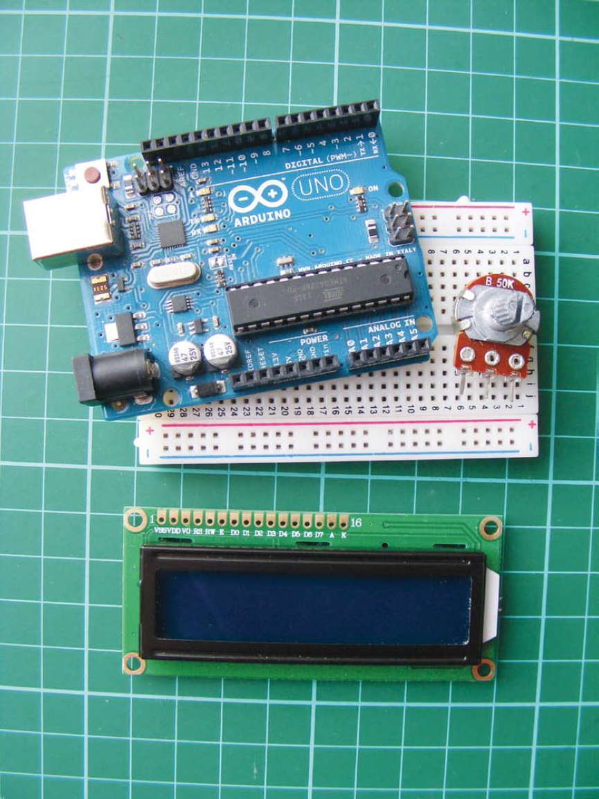
1. Place the LCD screen on the breadboard, inserting the pins into the breadboard holes. At the same time, place the potentiometer on the breadboard and connect the LCD, Arduino, and potentiometer using the breadboard and jumper wires, as shown in the table and figure 12-2.The LCD module has three GND connections, so use the breadboard GND rail for connections.
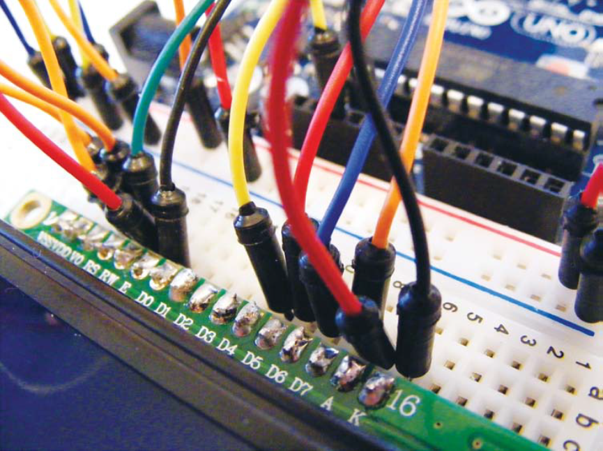
Figure 12-2:
Connections between the LCD and Arduino. Pins 15 and 16 are power and ground for the backlight.
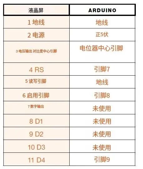
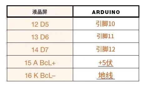
2. The center pin of the 50k ohm potentiometer connects to LCD pin 3 (VO). The potentiometer controls the screen contrast. Turn the potentiometer until the characters on the screen are clearly visible. Now connect one of the outer pins to GND, and the other pin to +5V.
3. The backlight LCD screen (see figure 12-3) has a built-in resistor, but if you are using a non-backlit LCD screen, you should insert a 220 ohm resistor between LCD 15 and +5V.(The packaging of the screen will indicate whether it is backlit).
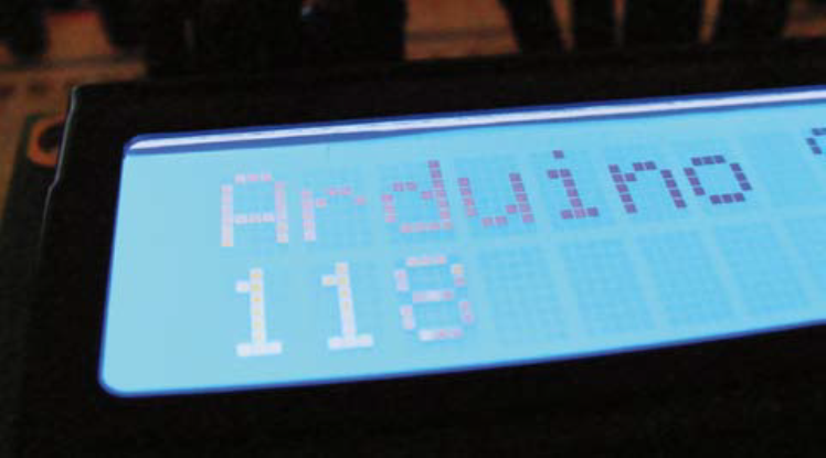
Figure 12-3:
Backlit LCD screen
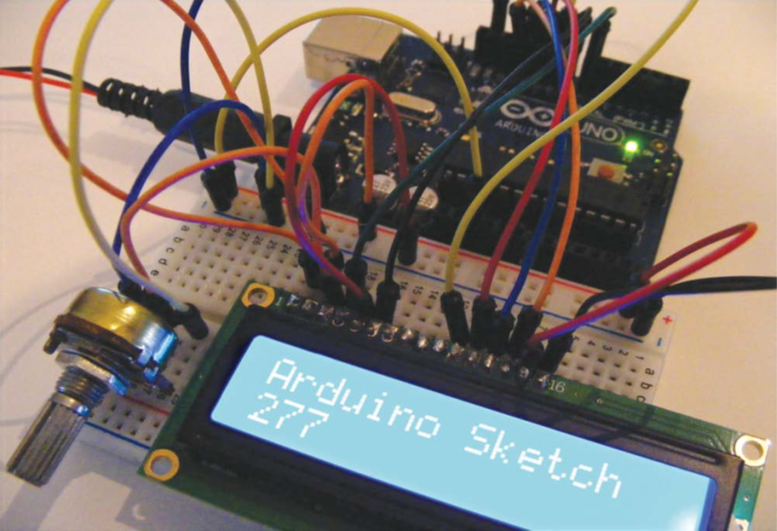
4. Your setup should look like figure 12-4. Check your work against the circuit diagram in figure 12-5, then upload
the code in the “Sketch”.
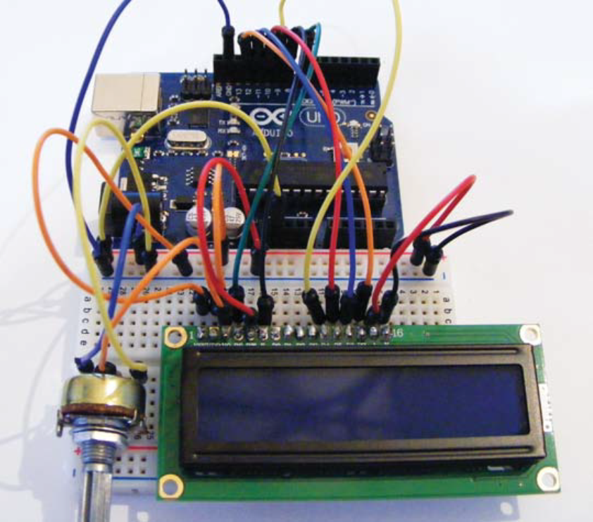
Figure 12-4:
Complete wiring and setup
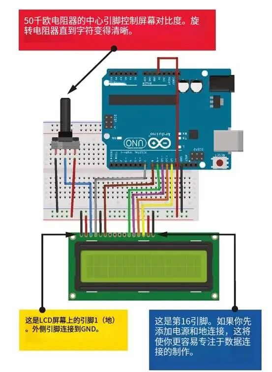
Figure 12-5:
LCD screen circuit diagram
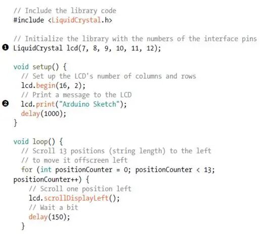
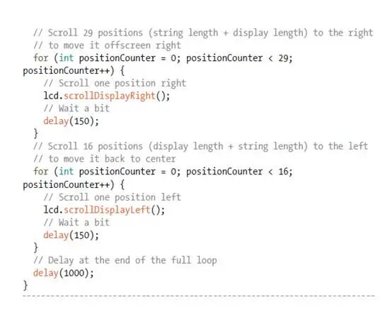
Sketch
The sketch is included in the IDE examples. Load the sketch from the File-Examples-LiquidCrystal by clicking on “Scroll“. This sketch uses the built-in LiquidCrystal library to send information from Arduino to the LCD screen. You can change the information by replacing “1” on the “Arduino Sketch “ with “Arduino Sketch”. To use this circuit setup with the example sketch in Arduino IDE, we also need to change the LCD pins in the sketch (12,11,5,4,3,2) to the pins assigned in the program (7,8,9,10,11,12), as these are the pins we assigned. I have recreated the sketch above, and you will see it in the IDE , but I made these changes.