Based on the x64 architecture, assembly language and operating system fundamentals are used to implement a simple operating system kernel in assembly language, demonstrating multitasking, multithreading, locks, and thread synchronization in a multiprocessor environment. Is this possible?  I believe no one would think this is a simple task.
  In fact, if you want to make it simple,
  it’s not a big deal.
  However, you need to take the initiative to find out the answer.
  Lean on your own shoulders
  and silently narrate
  . Here is your answer: the workflow of accessing and controlling the hard disk and graphics card involves initializing and determining the loading position, checking what is written in memory, and from which physical memory address the user program starts loading, as well as where the user program is located on the hard disk and what its logical block address is. app_lba_start equ 100 (the loader program declares a constant at the beginning) mov al, app_lba_start (transfer to register AL) phy_base dd 0x10000 (using dd to declare a physical memory address and initializing it to 0x10000)
 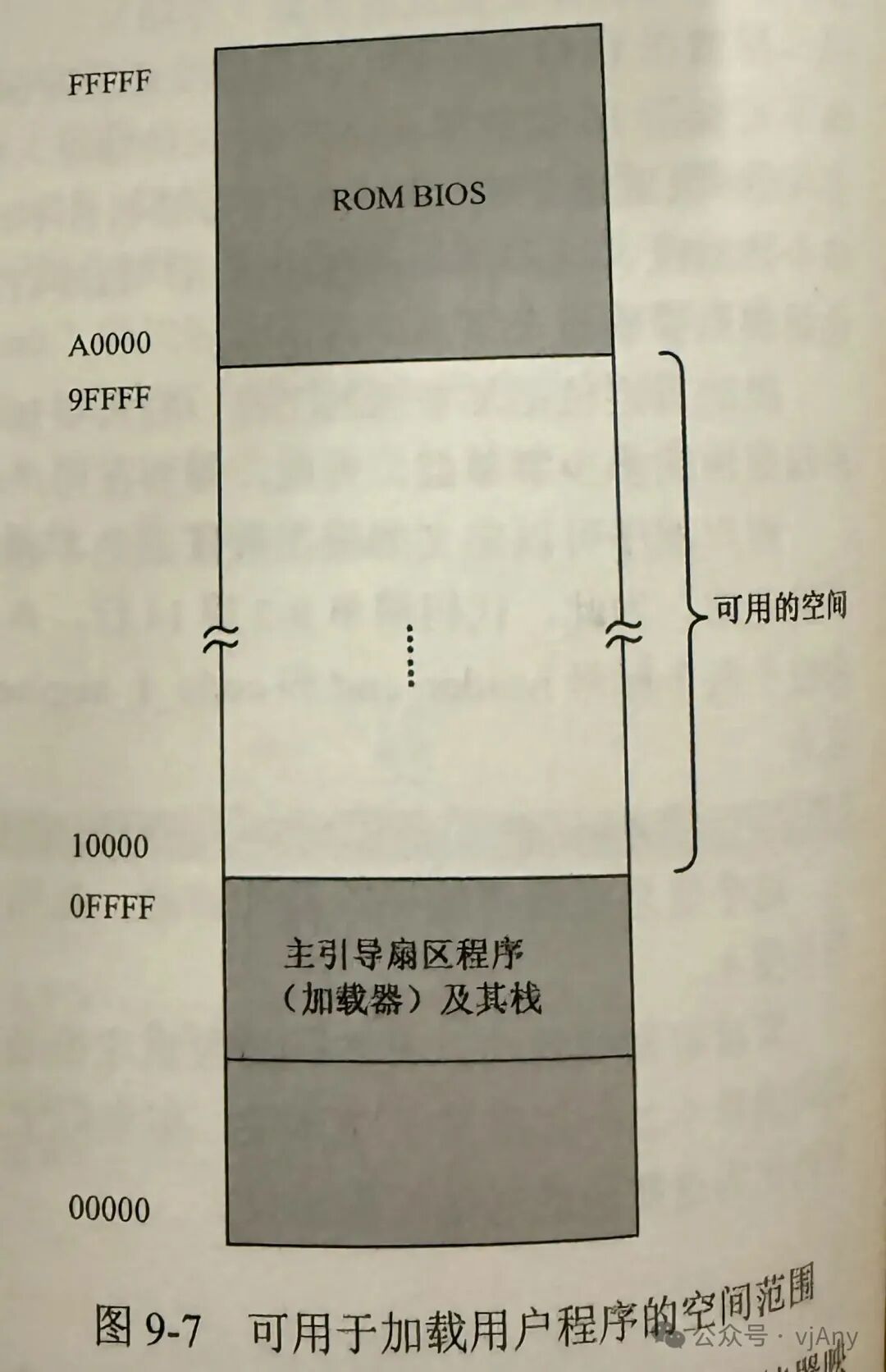 As shown in Figure 9-7, the physical address below 0x0FFFF is the realm of the loader and its stack: the physical address above A0000 is the realm of BIOS peripheral devices, where many traditional old devices map their memory and ROM into this space. Thus, the available space is from 0x10000 to 9FFFF, approximately 500 KB. In fact, if the low-end memory space is reasonably arranged, even more space can be freed up, but it is unnecessary as it won’t be used much. Preparing to load the user program SECTION mbr align=16 vstart=0x7c00 (defines the master boot sector program as a segment, where all elements’ assembly addresses will start from 0x7c00, which is actually stored in a double word at the label phy_base, a 32-bit value that can only be stored in two registers on a 16-bit processor. As shown in Figure 9-8, the 32-bit value is stored in memory in little-endian byte order, with the high 16 bits stored at phy_base + 0x02 in register DX; the low 16 bits stored at phy_base can be stored in register AX.)
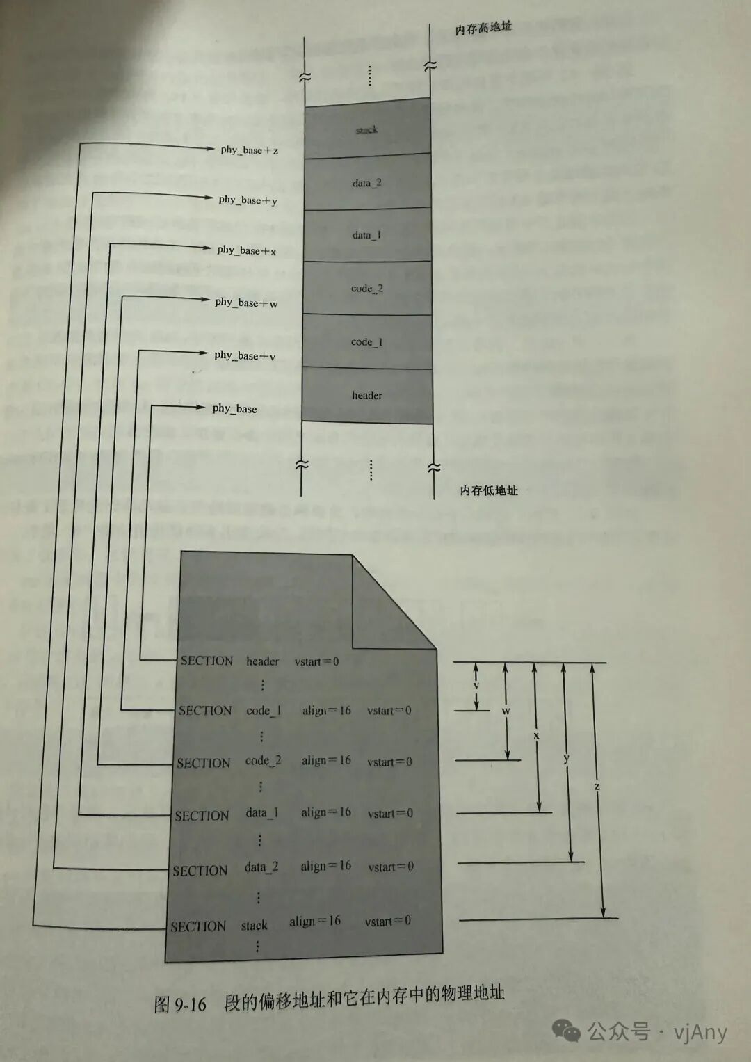
 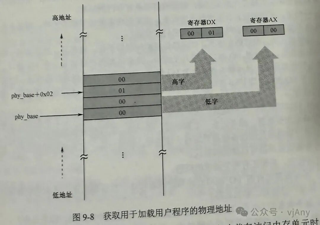 mov ax, [cs:phy_base] mov dx, [cs:phy_base + 0x02] (when accessing memory units, use the content of CS as the segment base address; the default content of segment register CS is 0x0000) The physical address must be converted into a 16-bit segment address; the program divides this 32-bit physical address (DS:AX) by 16 and stores it in register AX (0x1000). Peripheral devices and their interfaces download the next workspace from the hard disk to read the user program, which actually involves interacting with various hardware and processors. Many devices are not just hard disks, but also monitors, network devices, speakers, microphones, keyboards, and mouse lights. Sometimes, depending on the application, other devices may also be connected. Therefore, these devices that interact with the processor are called peripheral devices, and the glass pineapple element surrounds the processor for communication. As shown in Figure 9-9, the processor connects to the internal processing interface circuit of IC H through a local bus, and then connects to various port interfaces through the internal bus of IC H. The internal CH squeezes into some conventional peripheral device interfaces, USB, PATA, IDE, SATA bus structures. These are essential for computers, directly carrying the I/O port interfaces and port access to peripheral devices, and communication between processing and peripheral devices is done through the corresponding I/O interfaces. Specifically, the processing coefficient interacts with peripheral devices through ports, and the essence of this interface is similar to calculators, but the difference is that these traffic ports’ calculators are located in the I interface circuit. Reading sector data from the hard disk controller port is the basic unit of hard disk read/write. To read, at least one sector must be read; to write, one sector must also be written. It is impossible to read or write just a few bytes. This makes the data exchange between the host and the hard disk very fast, so the hard disk is a typical fast device. The most classic way to read/write data from the hard disk is to send the hard disk controller the sector number and the three numbers, which is called CS mode. This method is the most primitive, natural, and easiest to understand. The process of calling to read/write the hard disk is often required, and for the operating system, if every read/write operation requires writing a bunch of code, it would be cumbersome and annoying. Fortunately, the processor supports a mechanism called procedure call instruction execution. The procedure plot, also known as the process or program, regardless of how it is called, is essentially the same; it is a half-ordinary code. The processor can use the procedure call instruction to transfer to this code for execution, and when encountering the procedure return instruction, it returns to the next instruction at the calling point for execution. As shown in Figure 13, this is a schematic diagram of the procedure and procedure call. Loading the user program for the first time to read the hard disk will obtain the first 512 bytes of the user program, including the initial user program header and part of the actual instructions and data. To load the entire content of the user program, it is necessary to know its size and then further convert it into its procedure’s upper limit. As shown in Figure 19, the first double side of the program is the total size of the program, and the high 16 bits and low 16 bits of this value are transmitted to the calculator DS and S, because each sector has 512 bytes directly occupying 512, which is transmitted to the BS calculator, and in line 30, it is used for division operations. In a fortunate situation, the ranch needs to represent a certificate that is still a multiple of 512. After the departure, the calculator X is the number of sectors occupied by the user program design. However, in most cases, this punishment will have a remainder, an unexpected last distance, because it has not been networked and has not been included in the total upper limit. Regarding this issue, let me explain a little: hard disks are in units of sectors. If you want to write 513 bytes, it can only fill one sector. To save some hard disk space, no matter what, it must be filled with 512 bytes. Therefore, the software’s responsibility is to ensure that the hard disk receives 512 bytes. If it is not enough, it must be padded to make it up to 512 bytes. This will occupy two sectors, and only one useful display will be shown, while the other 510 bytes are used for padding. As for which data in a sector is useful and which is padding, it is the software’s responsibility. Thus, the user program itself, through constructing the header, ultimately determines its own size. Therefore, it is necessary to judge whether it is in the sector. If it is not in the sector, it will transfer to the subsequent code to gamble the remaining sectors. If it is in the sector, why? Why is it not in the sector? Regardless of whether it is in the sector, it still needs to be simplified. Because it has already read one sector, note that the length of the user program may be less than 512 bytes or exactly equal to 510 bytes. In either case, the content in calculator X must be zero when the user program executes to line 38:00. Therefore, the arithmetic comparison in line 38 is significant, and line 39 is a conditional transfer instruction. However, when the content in calculator X is zero, it means the user program has been fully read, and no further reading is needed. After all, the user program only occupies one byte. The position where the user program is checked is pointed to by the computer’s DS and ES, which can only point to a maximum of 64 KB in a logical segment. However, when the user program is particularly large, it cannot fit into the checking segment. The logical address in the segment extends from 0x0000 to the maximum value of 0xFFFF. To solve this problem, the best method is to always load the data into a new logical segment at the tail of the previous data. This is because each segment is 512 bytes. The address difference between each segment is 0x0200, which is equivalent to dividing by 16 or 0x0000. This is the difference between the segment addresses. Each time a new segment is constructed, it is necessary to increase the previous segment address by 0x0200 to obtain the new segment address. The change of the segment address is temporary and is only for reading the hard disk. Therefore, the current data segment register DS’s content is saved to restore it in the future. The remaining sectors of the user program are transmitted to the calculator X for subsequent instructions. If the instructions are used, it is necessary to prepare to use a loop to read the entire user program. The current data segment register DS’s content is based on the original foundation +0x0200 to construct the next logical segment, and the next logical sector is read from the hard disk, and the function of the segment offset is executed. Each time the transfer is done in a new segment, the address must be pointed to the next logical sector before each transfer. The process of calling the hard disk is disk_zero and starts the next round of the loop until all sectors are read. The content of calculator CX is zero. The user program relocation: when writing the user program, it is segmented. Therefore, the next step of the loader’s work is to calculate and determine the segment address of each segment. As shown in Figure 916, the user program defines six segment points. Each segment’s address is calculated relative to the beginning of the entire program. Therefore, the first segment head is located at the head of the entire program, so its base address is zero. From the second segment, each segment’s base address is relative to the beginning of the entire program. We do not know the exact base address of each segment, but we can use numbers to represent it. Thus, the base address of the second segment is the base address of the third segment, and so on. The last assembly address is as follows: now the program has been fully loaded into memory, starting from the physical address PH. Thus, each segment’s physical address in memory is based on PH. The first segment’s physical address in memory is PH + 0, the second segment’s physical address in memory is PH + 0x0200, and so on. The last segment is PH + 0x0200 for loading the user program, which is aligned to 46 bytes. Each segment’s base address in the user program is also aligned to 16 bytes, which means that their addresses in memory are aligned to 16 bytes.
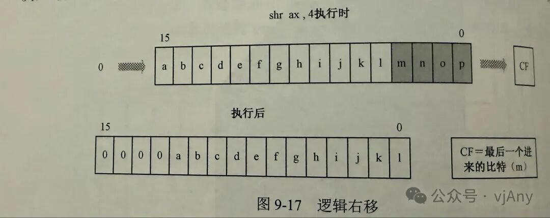
  Restore the content of the data segment register DS to point to the position where the user program is loaded, which is the header of the user program, and then use it to locate the entry point of the user program code. Next, define the procedure X game SEGMENT base to accept a 32-bit base address, and after the calculation is completed, the program is assigned a 16-bit logical address. The calculation process must not destroy the content of the calculator DS, so line 137 is used to save it. In line 139, now the user program is at the physical address of the 16-bit segment added to the content of register IS. The address part of this instruction uses the segment register CS, and it does not add 0x07700, which has been explained before. In the city, the data segment and code are separated, and the current code segment’s definition part uses the VS large vehicle 0S 770 quality drama. Finally, in line 140, the high 16 bits of the address 70 are added to the memory calculator DS. ABC is a carry addition, which adds the destination operand and the original operand, and then adds the flag calculator C or so that two steps can complete the addition operation of 32-bit numbers. Now, in the second time: A S has obtained the entry code segment. In fact, the physical address only needs to shift these two 32-bit numbers by four bits to obtain the logical segment address. The trouble lies in how to move them separately in two memory units. The answer is to move them separately and then concatenate them. The calculator in line 141 uses the logical EHR shift log right to add the content in register X to shift right by four bits. As shown in the figure, the logical right shift instruction execution shifts the operand continuously to the right by the specified number of times. Each time it moves, the bit that is squeezed out is moved to the flag for the gasping device C F bit, leaving the left side empty, and the position is filled with bits.
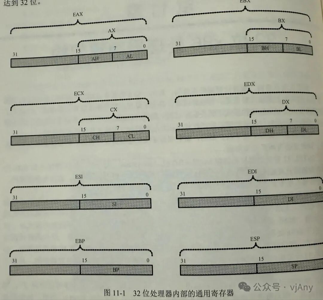
  The destination operand of the SHR instruction can be an 8-bit or 16-bit general calculator or memory unit. The original operand can be an 8-bit immediate number or a calculator. We have introduced the previous method, and in the future, we will use a new method to represent the instruction format… Handing over control to the user program. Now the user program is ready in memory, and the remaining work is to hand over control of the processor to it. The handover work is simple. The code list 976 loads the user program entry point through a 16-bit indirect absolute transfer instruction, as shown in Figure 95. The entry point is two consecutive lowest knowledge addresses located at the user header, which is at 0x0004, leading to the address located in the user program header, which is at 0x0006. Because the loader’s new working address has been relocated, when the processor executes the instruction at M batch X 0004, it will access the segment address DS, and the data segment from the address 0x0004 will extract two words and transfer them to the code calculator CS and instruction calculator IP to replace their original content. Thus, the processor is brainwashed and automatically transfers to the specified location to start executing. The processor has run to the user internal program for execution, so the remaining work is to重重用户程序的工作流程,不过在此之前还是先总结一下,无条件转移指定在IP的用法8086处理器的无条件转移指令相对转移相对操作码是操作相对于目标位置的量减一个字节是有个制符号数,至于由于这个原因,该指令属于段内转移指令,而且只允许转移到距离当前指令付128到二七自己的地方相对短转移指令是使用软件是short,例如GB short INFINITE H编辑器检查标号应Rant所表示的只如果速度超过一个自己所能允许的数字范围则无法通过变异,否则便宜器用目标配置的会编地址,写当前指令的下一个指令会编地址,保留一个自己的结果,作为机器指令的插头速相对短转移指令的汇编语言操作数只能是标号和素质下面是直接使用素质情况检验B说的连S二的钱,但树脂和标号是等价的再便宜些,那都被用来计算一个八倍的便宜在执行指令时不理细胞指令中的操作数加到指令计算器IP上,这会导致指令的执行流程转向目标地址16位相对进转移和相对短转移不同16位相对进转移指令的转移范围更大,他的脾气指令操作吗?为零S一九了解开指令的长度为三字节操纵码零29,后面还有一个16位二自己的操作数,因为是转移属于段内转移下对的意思是同样是指它的操作数是一个相对量,相对于目标位置的处的偏移量,在原程序边阶段编辑器用目标位置的配变地址减去当前指令下一条指令的汇编地址保留社会结果,作为机器指令的操作与这是一个16位的有数户,可以转移到距离尺指令付32768到32767至节的地方,12位三队转移指令应当使用关键是利 GMP利了in find night JP粒零3000再找些NASA版本中,关键胜利是可以省略了,若没有指定说的利润那么便宜,其实都默认胜利,但是最近版本有改变这些规则,如果没有指定关键这或者利润,那么如果目标标位置距离当前指定负二八到二七次截止自用采用锁的,否则采用利16位,间接绝对转移这种转移方式转移机子在端内转移,但是转移到目标偏移地址不是在指令中职业给出而适用一个16位通用计算器会内内存地址来接给出的,比如JP立ABS GMP力CS指令中环境正义也可以省略卷,间接绝对接近转移版,原本就是利以上年和整列式处理器计算器CS的内容取代指令计算器IP脑袋内容以上是目标偏移地址位于通用计算器情况当然该偏移,地址也可以位于内存中,而且这是最常见的力度在某具衡器的的数据,但说明了编号间,PS B处是一个字GPS的DCS零零并而且假设我们迎知道他是转移目标的,其实便宜地址,那么在该行区的代码锻炼就可以使用以下16位,间接绝对金转移地址在IPS IP省略智利本级但当这条决定执行式处理器访问有计算器DS指向的数据,从指令中指定的偏移地址竖起了一个字,这里是灵儿,并且该字取代指令计算器IP当前内容当前,当然既然是间接寻找目标位置的天,以地址其他君子方式也可以的,比如GPS GPS + S I注意在PPS和在PPS四完全不同的,不要发礼物选择要转移的觉得地址位于继承GPS中厚者便宜地址为以BS说指下的内存单元中是十来位绝对转转移好找以前我们曾经哦这样子定在NBA是零零零零零:零S 7700这里00000207700分别是地址和地址符合当地便宜地址的表达习惯,在编辑之后其机械时因为以007700000 X E是操作码,后面是操作数注意制的惩方式按照低端制接续的,而且在编译之后便宜地址在前段地址赛后执行这段指令后处理器用指令中给出了断地址代替计算器CS运营内容用给出了偏移地址代替IP地址原额用成活跳到另一个不同的代码段中,即实行一个段间转移 56位,间接绝对转移批发边转移的目标壁纸,可以通过访问内存来进行 得到, 这叫 间接 转移, 但是 要 使用 关键字, 例如 在 用户 某 程序 的 数据 端 中 设 明的 标号 者 mP 发, 并在 其后 处 示 两个 字 GMP 法 第 零 三 零 零 零 二 四 零 零 零 零, 这 不是 两个普通的数字,他们分别是某个程序片段的片和 地址 和 段 地址, 为了 转移到 该 程序 片段 上 执行, 可以 使用 下面 转移 指令, GMP 发展批法,关键是化的作用是告诉编辑器该指令应当变异与成一个原转移地址原转处理器执行社段指令后,该计算器是所指这样的数据,但从指令中给出了偏和地址处取出两个字分别用来代替计算器CS指令经常器IP内容不过最好的例子还是本站清单九杠的第76行这批发零四零40位间接绝对转移指令的操作数,可以是任何一种内存殉职指令出了下面粒子下面还可以组几个,这MB发BS在MB发BS + S最后16位的意思,事业转移到目标地址便宜地址是16位检测点9.3以下指令执行后计算器X内容是多少?NVAS零五AARRAS 8SHRS二按题目的要求写出双音的指令,无条件转移到当前段内标号LabelPROC无条件转移到当前段位的另一个位置便宜地址在计算器B X处无条件使转移到当前的另一个位置,便于地址保存在当前附加段内计算器BS向内存单元处中无条件转移段地址为NS F零零面地址为040002无条件转移地址和偏低,承诺到当前数据段内篇以地址零S八零的地方抵制的目标是的地址高至为目标处段地址无条件转移,按地址和偏移地址应的存发站当前附加段内低地之以低节为目标的偏移地址高质为目标的断例,这两个地址当前副驾段内的便宜地址可以用BS + D I价,而是八零得到32倍是八六处理器编程架构AA 32架构的基本执行环境计算器的扩展才16位处理器中有八个通用计算器,ABSSDSSIDIBPSB,其中显示还可以拆分为两个独立的八倍存储器来使用GHALBLBHCHCLDH和L要如图是一所四32倍处理器,在16位处理器的基础上扩展了这八个通用存储器的长度时达到32倍
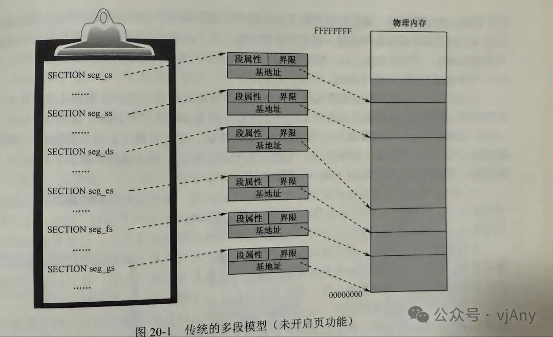
 基本的工作模式8086具有16位的段存储计算器,指令至尊计算器和通用计算器SSSDSESIBSBSCSDSSIDIBSP是我们称他为16位传统处理器,尽管它可以妨碍MB的内存,但是只能分担进行,但是由于只能使用16倍的短片一样,端的长度最大只能是64 KB零八六只有一种活动模式即时模式,当然这个名称是后来才取出来的线形地址和分页为爱艾32处理器编程访问内存是需要在内存中给出断地址和变量,因为分段是AA三二架构的基本特征之一,传统上端地址和平原地址称为逻辑地址便宜地址叫作有效地址以非R A在指令中给出有效地址的方式叫做荀子方式,as in made,比如ING what BS + S I +0S零六在这里只用中使用的是及时加便池的方式来寻找最终的操作数有效地址是BS的内容,加上S II内容+0 S来得到断的管理是由处理器的端部件负责进行的部件加端地址和平原地址相加得到访问内存的地址,一般来说,端部件产生的地址就是物理地址,三二处理器是是多任务,在多任务环境下人物的创建需要分配内存空间,担任物种之后还要回收他所在的内存地址,在分段形象内存的分配是不订场的程序越大就分配已到内存程序,小时收费影响时间长了内存地址就会顺变化,就有可能缺种情况,对什么地址是有的,但都是小块,无法分配给某个任务,为了解决这个问题而12处理器的翻译功能,专业奖,物理地址,内存空间完成逻辑上的一带一般是四开笔通过使用一可以简化内存管理,如图示一三所示应功能,其中后端部件产生的地址就不再是物理齿,而是显性粒子能力而缺时间的地址,还要经过业部件转才是物理地址现代处理器的结构和特点流水线高速缓存扣款的因素在运行时所需要的局部规律,首先采取查查,反正最近刚刚反弹过的确定了实力或者与他们想您的企业或持续提供程序完满时序列化的从内存中取值实行循环操作实施行一段固定的反面数据是要反过来内容共享在一起乱序执行为了和谁有什么相处才能非常的努力支持部分稽查成为操作的OK享受,寄存器重命名分支目标预测32位处理器的寻址方式程序的动态加载和执行内核的结构、功能和加载内核的结构内核的加载安装内核的段描述符平坦内存模型和软件任务切换多段模型和平坦模型一直以来,我们都工作在分段的内存款模式上,如21所示,在保护模式下,首先按程序的结构分段创建各个端的描述符都有所指向,物理内存的各个段要收服中的基地给出了端的趋势,物理地址接限制给出了断的长度,属性值只是了断的类型和特权级别等性质虚拟内存管理的方法是端的换路况处用到哪个段时间?它调入物理内存将P位置一,如果内存不够,则将某个端画出磁盘加P微,请您登录空间可以需要访问的。
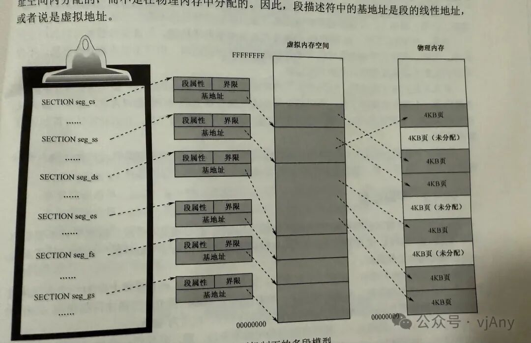
 传统的多大模式适用于开启了液功能之后的环境系统如图20所示,首先依然是按程序的结构分段,创新各个端的描述,但是端在任务自己的虚拟地址空间内分配,而不是在物理内存中含对饮食大毛舒服中的地址是段的线性地址,或者说虚拟地址
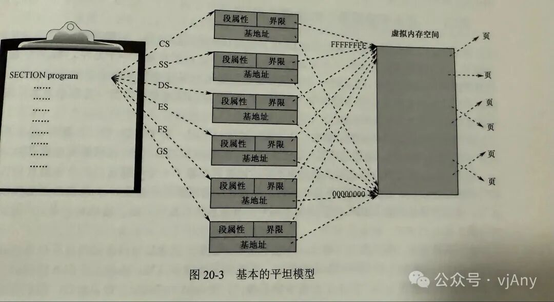
 平坦模型多少管理性成为平常模式今晚说是分担单,千万不要心里非常很大,适应要有技术是按照当地一截平行,所有全部是GB的整体沙发较大档的处理十分能想到去化销售的模型下,所有大都是美国的数幅都指向市区比的断断的机制,DC地址从来都是00零零零零零零零断线都是零 FFF力度为是在纵容基本的引导模式下程序在编写的12部分段保留一段代码和数据都要这个段位互相连接衔接,但一般并不交叉,而且蓝色种模式下不能享受到,但保护气质的好处,性和速度访问的检查仍然信息,但从不会产生伪劣的情况原理很简单,构断描述的基地的都是力实际使用的断界线都是零FFF FFFFF任务耐打地址空间而言,对任何内存位置的访问都是合法的,需要强调的是二位保护膜,作下非谈模型并不是不分单只是分一个小段,而是说所有断的大小都是数据所有大描述符的机子都是零大界性为最大,实际上整个系统中需要定义两个端机,可以是代码一次数据斩断也使用普通的数据段,对于保护模式来说,平衡模型不是处理器的工作模式,他只是我们采用的一种内存访问手段,你只要不要采用多段模式,只要把这个那种看中一个就可以认为使用了给他模型上面说一下,对于64位处理器来说,如果工作在64位模式下这平台模型不适合选的,而是使用的。
 Initializing the system and loading the kernel. As online, our system starts running from the master boot program. First, look at the code. Please set two backrests at the beginning of the program, which are the kernel’s physical consciousness and content program on the hard disk. Logically, there is a program definition that has practical significance. Its role is to organize code to calculate the unit number of the assembly address. After all, in the segment address definition, there is a st verse, and it defines a virtual address with X 0007700. Therefore, the assembly address of the segment label will start from 07700. In the master boot program, lines 11 to 13, we set DS and SS to zero. The actual physical address loaded by the master boot program is S 7700, or the master boot program in the data segment, which is actually 0700. When reading the segment address, it can be directly used as the exercise address without adding 7700. Defining the flat model under the segment descriptor, the next task is to create a global descriptor GDP and install the necessary segment descriptors, but we need to decide where the GDP is located. This position is where we want to recharge the store’s main idea to open a specific physical example at 0x000080000, with one used to specify the boundary limit value in the program description. The number of descriptors is filled here, defining six bytes. On the one hand, it modifies the specific position; on the other hand, it is also for the future download of the global descriptor inheritor GDP, which belongs to the program execution in the actual mode using logical addresses. Therefore, in lines 17 to 20, the number of descriptors is obtained from the DT, which is the physical meaning of the logical address transmitted to the DS segment address. Next, create and install segment descriptors and re-differentiate these particles. Four descriptors are created, respectively, from the selected representative segment, the data large descriptor of the third privilege level, and the code descriptor of the third privilege level. These descriptors, except for DPI and the type, have the same attributes, and the address is zero. The segment connection is changed to the maximum instruction X FFFFF, which is four KB in the flat memory model. Since the segment is already at its maximum, there is no need to create multiple segments to access all memory. However, the code segment type and privilege level can only be used for execution, while the data segment can be used for reading and writing. The kernel’s work leads to the privilege level of the user task work in the upper characteristics, which can access the privilege level. Therefore, we need to create at least four or more codes. These segments all need the same verse length. You may wonder why the medical kit collection code segment and data descriptor are not provided. This is not necessary. Most popular systems recharge using 0 grams of risk collection production models are sufficient. The new law segment check is a special data large, but it can also be used as simple data. When we create and small code numbers, we create a global descriptor icon, and the calculator GPT enters the protection mode. The JP instruction creates the code descriptor and refreshes the calculator CS here, leading to x 0x000084 data B. The code segment selection is because this segment base is zero, so the label represents a segment. Once it is also a physical address, because the main medical program is downloaded from the physical address, it should be information zero. By analyzing, we know that the physical nature of the law and number is 0778, and in the current segment definition, there is V large equal to 0 S 0x00007700. The distance is also the physical address in memory. The next step is to refresh DS, ES, FSS, and SS with the newly created data segment descriptor. All these calculators point to a data segment processing and set the nature of this instruction. We use the leading editor to add the extended data segment as a diagnosis from the address 770 or above, which is the guiding principle when the program is reduced and pushed down. Next, we will still discuss any program completion and initialization. Before that, we need to know the layout of the kernel in the flat model under the kernel program loading.