Hardware
-
Arduino Nano R3 × 1 -
SparkFun A4988 Stepper Motor Driver Board × 2 -
Stepper Motor, Mini Stepper × 2 -
DFRobot MPU-6050 6 DOF Sensor × 1
Modeling
Simulation scenario: https://www.kaggle.com/zjor86/simulations-self-balancing-robot
I have detailed the project’s model and simulation scenarios in the link above.
I strongly recommend that everyone also simulate before building the system and adjust parameters in a virtual environment.
Device Selection
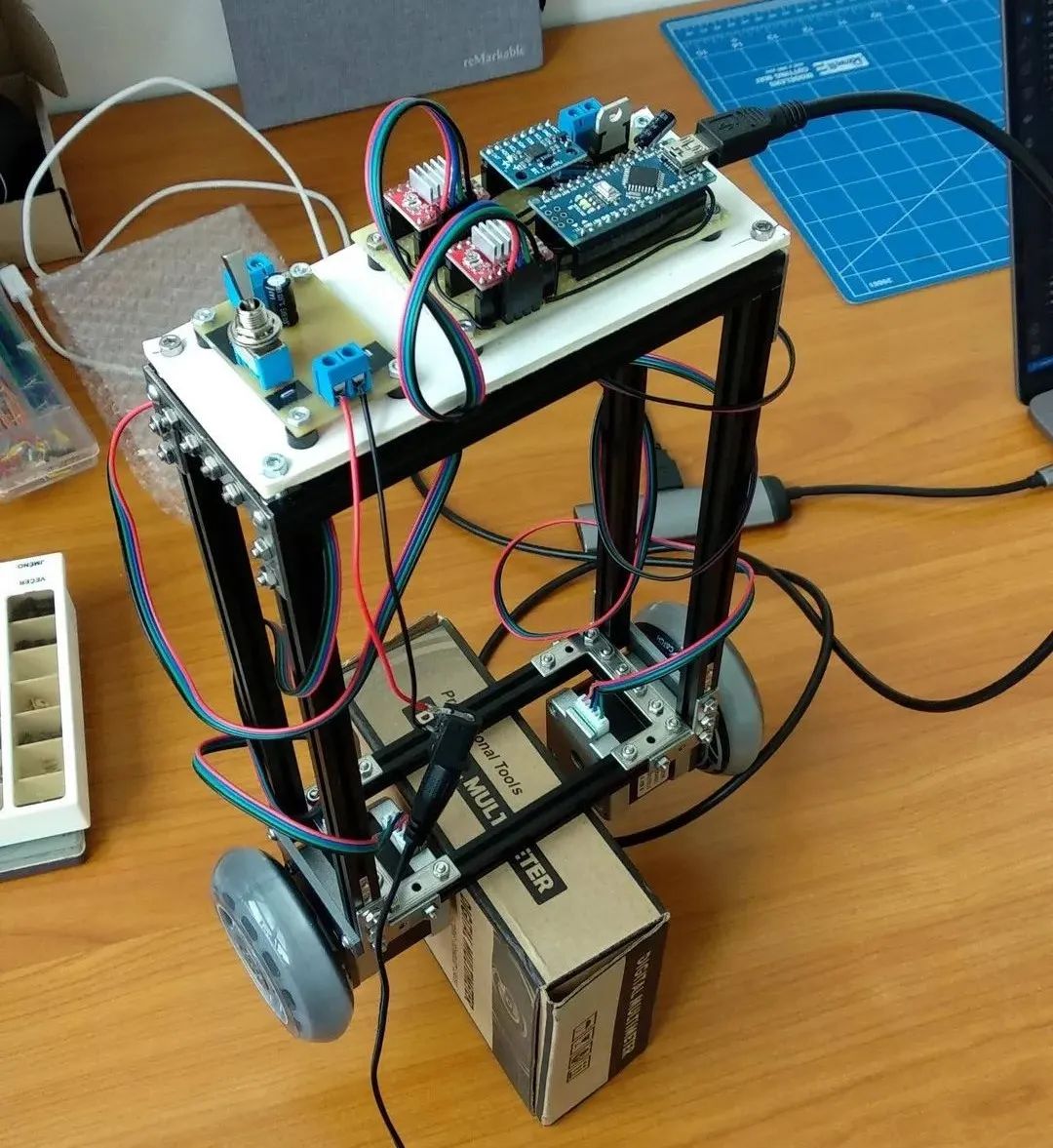
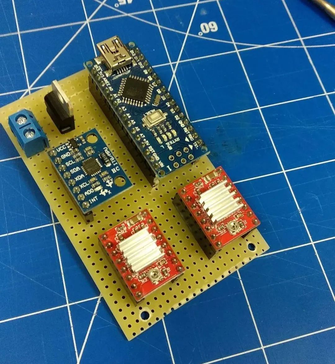
So far, the setup is as follows:
-
Arduino Nano, 16MHz, I tried to squeeze as much computational power out of the board as possible, and may later replace it with BlackPill (100MHz) or ESP32 WROOM (80-240MHz). Experiments have shown that frequency is a very important factor. -
Nema 17 Stepper Motor × 2 -
A4988 Stepper Driver × 2 -
MPU6050 – Gyroscope and Accelerometer with onboard DMP; I also tried using the more advanced MPU9250 chip, but have not yet found good library support.
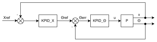
Feedback Control Loop
I used two embedded PID control loops, one to maintain an upright position;
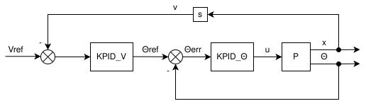
the other to stabilize speed or position.
Implementation Instructions
Stepper Control
The robot balances itself by applying a force that is roughly proportional to the angle. This means the motors should rotate with acceleration. Since we have stepper motors, we need to calculate the delay for the next step, preferably after each step (or as fast as possible).
However, stepping itself is time-precise, so I used a timer interrupt for stepping at a frequency of 40kHz (I tried frequencies from 8kHz to 100kHz, which worked well, but it consumed CPU cycles and the control was not very smooth). This process should be as fast as possible and should not include any floating-point calculations.
Speed Update
The next time-sensitive task is to update the speed and recalculate the step delay, which should be faster than measuring the speed at which the route is running; otherwise, the force will not have enough time to act and produce an effect.
Control Loop
This program is responsible for reading the IMU (MPU6050), calculating necessary control signals, such as the acceleration for the speed update loop.
Using DMP
The DMP (Digital Motion Processor) is responsible for merging data from the gyroscope and accelerometer, providing you with nice and smooth yaw-pitch-roll data. It offloads the slow CPU of the Arduino, and in practice, I achieved 5 times the main loop speed compared to using a hand-written complementary filter after switching to DMP.
Schematic Diagram
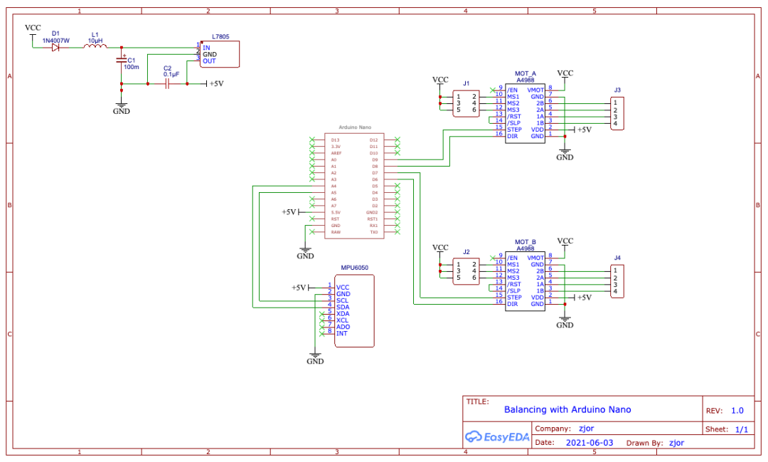
▲ Click to enlarge
Project Follow-up
I will share my improvements and follow-up upgrade plans. If anyone is interested, feel free to join in.
Future considerations include:
-
Using a more powerful CPU (BlackPill, ESP32) -
Adding remote control capabilities via WiFi, BLE, or nRF24L01 -
Turning it into an educational kit that is easier to assemble and understand -
Transforming this robot into a platform with an API, allowing other devices to be installed on it