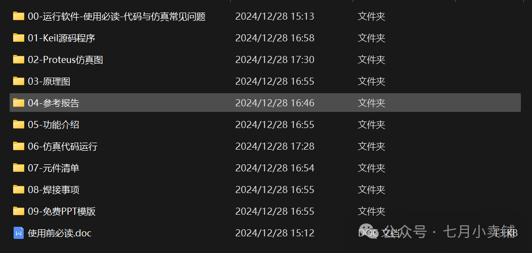
Click the link below to read the original article or copy the link to your browser to obtain the Keil source code and Project Backups simulation images:
https://gf.bilibili.com/item/detail/1107885063
C+15
Abstract
With the advancement of society and technology, the application of electronic devices in various activities has become increasingly common. Buzzers, as a tool for answering questions, have emerged. Buzzers are widely used in quiz shows, knowledge competitions, and other activities. However, existing buzzers on the market have issues such as complex circuits, poor practicality, and high costs. Therefore, this graduation project utilizes the C51 microcontroller to design a simple structure, easily procurable components, and a fully functional multi-way buzzer.
The multi-way buzzer adopts an eight-way answering format, with the AT89C51 microcontroller as the core control chip, using a four-digit digital display to support eight contestants answering. Before the host presses the start buzzer button, if a contestant presses the buzzer button, the system will emit an alarm, which is considered a violation. In the normal answering procedure, the system enters a 30 second countdown, during which contestants can answer. If successful, they enter a 15 second question countdown. If no one answers in the last 5 seconds, the system will issue a reminder. Additionally, the host can set the answering time and buzzer time.
This design is based on Altium Designer for schematic design, using DXP software for component searching, placement, connection, and PCB design to achieve hardware design; utilizing Keil uVision4 for microcontroller program writing to achieve software design; and finally using Proteus 8 simulation software to load the program into the microcontroller for simulation debugging to meet design goals.
Keywords: buzzer; C51 microcontroller; hardware design; software design; simulation
Microcontroller; digital display; buzzer; electronic products; proteus
Table of Contents
Chapter 1 Overview
1.1 Source of Topic
1.2 Current Research Status of the Topic
1.3 Significance of the Topic
1.4 Content of Thesis Design
Chapter 2 Overall Design Scheme
2.1 Multi-Way Buzzer Design Scheme
2.2 Component Selection
Chapter 3 Hardware System Design
3.1 Overall Design Scheme of the Eight-Way Buzzer
3.2 Minimum System Design of the Microcontroller
3.3 Key Module Design
3.4 Buzzer Module Design
3.5 Digital Display Module Design
3.6 Power Supply Module Design
Chapter 4 System Software Design
4.1 Programming Language and Development Environment
4.2 Program Flow Design
4.3 System Program Debugging
Chapter 5 System Simulation
5.1 System Simulation Software
5.2 Schematic Simulation
Chapter 6 Physical Welding and Debugging
6.1 Component List
6.2 Circuit Board Welding
6.3 Physical Debugging
Chapter 7 Summary
Acknowledgements
References
Appendix
Chapter 1 Overview
1.1 Source of Topic
During my university studies, I developed a strong interest in designing circuits based on microcontrollers and their practical applications in life. This graduation project was based on the guidance of my supervisor, combining what I learned, and selecting the design of a multi-way buzzer based on microcontrollers from the reference topics provided by my supervisor.
1.2 Current Research Status of the Topic
Currently, there are various types of buzzers on the market, mainly divided into electronic buzzers and computer buzzers. Electronic buzzers have a simple structure, relying on digital integrated circuits, usually consisting of a buzzer host and buttons, with limited functions; while computer buzzers require a computer to operate specialized software to achieve multiple functions, with a wide range of applications, but large size and inconvenient use.
With the rapid development of technology, buzzers, as early developed electronic products, are widely used in talent selection and knowledge competitions. However, early buzzers mainly consisted of several transistors, thyristors, and light-emitting diodes, with low reliability and implementation difficulties. Currently, most buzzers still have the following shortcomings: first, the complex wiring connections on-site lead to confusion due to different contestant positions, affecting reliability and on-site aesthetics; second, there are many misjudgments, where contestants successfully buzz but are not recorded, affecting the fairness of the competition; third, the success rate of production is low, due to imperfect technology and complex component assembly, failing to achieve expected functions, resulting in waste.
1.3 Significance of the Topic
In competitions, the traditional hand-raising method for answering questions is easily influenced by the subjective judgment of referees, affecting fairness. Therefore, designing a simple and reliable system to achieve standardized buzzer functions is particularly important.
The microcontroller is a chip widely used in electronic products, which has developed rapidly in recent years and has become the first choice for electronic product development. Microcontrollers have advantages such as lightweight, small size, low cost, and strong anti-interference capability, making multi-way buzzers designed based on microcontrollers superior to traditional buzzers: first, the circuit connection is simple, with many functions (such as timing, interrupts, resets, etc.) and pins integrated in the microcontroller; second, strong practicality and reliable operation, allowing for diversified functions through programming, facilitating the addition and improvement of functions. Therefore, this design is innovative.
This multi-way buzzer utilizes the AT89C51 microcontroller for system design, helping to master relevant knowledge. In terms of hardware, it uses DXP schematics for design, improving design capabilities; in terms of software, it writes microcontroller programs, deepening understanding of programming; in terms of physical assembly, it involves component assembly, soldering, and debugging, enhancing hands-on skills and troubleshooting abilities.
1.4 Content of Thesis Design
This design and production thesis of the multi-way buzzer is divided into seven chapters:
The first chapter is an overview, discussing the source of the topic, its significance, and the structure of the thesis, determining the research direction.
The second chapter is the overall design scheme, describing the design process of the multi-way buzzer and the software used, considering component selection to ensure normal operation.
The third chapter is hardware system design, adopting a combination of overall and partial narrative methods, introducing the overall scheme and various input/output modules, such as the key module, digital display module, and buzzer module.
The fourth chapter is system software design, using C language to write programs, inserting flowcharts and accompanying text descriptions to clarify software design.
The fifth chapter is the system simulation part, simulating the schematic and function debugging through Proteus software.
The sixth chapter is the physical welding and debugging part, listing the component list, welding principles, and function debugging.
The seventh chapter is the summary part, summarizing design functions, encountered problems and solutions, and the knowledge learned through this design.
Chapter 2 Overall Design Scheme
2.1 Multi-Way Buzzer Design Scheme
The theme of this paper is the design and production of a multi-way buzzer based on microcontrollers, adopting an eight-channel buzzer method, with the AT89C51 microcontroller as the core to design a practical eight-way buzzer.
The eight-way buzzer is centered around the minimum system of the microcontroller, with the input part including the key module and power module, and the output part displaying and alarming through the digital display module and buzzer module. In hardware design, it uses DXP software for component selection, schematic design, and PCB production. In software design, it uses C language to write programs in the Keil4 development environment. In simulation, it uses Proteus 8.0 software for schematic drawing and functional simulation. In the physical assembly part, components are purchased and soldered according to the schematic, ultimately achieving the expected functions.
The basic function of the eight-way buzzer is to support contestants’ buzzing and related display. After connecting to the power supply, pressing the switch will display “0000”. Before the host starts, if a contestant buzzes early, the digital display will show the contestant number and emit a warning, and the buzzer will sound. After the host presses the buzzer button, the digital display enters a 30 second buzzer countdown, with the buzzer sounding in the last 5 seconds; if no one buzzes, the round ends, and the digital display shows “—-“. If a contestant buzzes, the digital display shows the contestant number, entering a 15 second question countdown, with the buzzer sounding in the last 5 seconds. After the question time ends, the digital display shows “—-“. After this round, the host can reset using the reset button. Additionally, the circuit can adjust the buzzer and question time through the time setting button.
2.2 Component Selection
2.2.1 Selection Principles
This multi-way buzzer consists of multiple modules, including the minimum system of the microcontroller, key module, buzzer module, digital display module, and power module. To ensure that each module achieves ideal functionality and works closely together, component selection is crucial.
Before drawing the schematic using DXP software, it is necessary to select the required components from the component library. When selecting components, first consider whether the functions meet design requirements; secondly, choose components with a good cost-performance ratio that are easy to obtain; for components that require packaging, choose the appropriate type of packaging; for components with parameters (such as resistors, oscillators, etc.), select suitable parameters based on hardware design needs; for polarized components (such as polarized capacitors, transistors, etc.), pay attention to direction and model to avoid simulation failures due to similar components; finally, try to choose common and easily obtainable components for convenient physical soldering.
2.2.2 Component Selection for Each Module
(1) Minimum System of the Microcontroller
Component selection: 1 AT89C51 microcontroller U1, 1 nine-pin resistor (102) R1, 1 10μF capacitor C1, 1 10K resistor R2, 1 12M oscillator, 2 30pF capacitors C2, C3, and 1 key K11.
The reason for selecting the AT89C51 microcontroller is its small size, ease of use, availability, good cost-performance ratio, and powerful functions. The nine-pin resistor is used to connect the pins and the microcontroller to output 5V voltage, with one connected to VCC, and eight connected to the digital display segment selection terminals. The selection of the 12M oscillator is to generate 12000000 sine waves per second to ensure accurate timing.
(2) Key Module
Component selection: 10 independent keys K1 to K10.
The keys K1 to K8 correspond to the buzzer buttons for eight contestants, connecting to the microcontroller’s P1.0 to P1.7 pins; keys K9 and K10 are the start buzzer button and time setting button, connecting to the microcontroller’s P2.0 and P2.1 pins, respectively. Each independent key has four pins, and only two corresponding pins need to be connected during wiring.
(3) Buzzer
Component selection: 1 PNP transistor Q1; 1 buzzer DEEP1.
The reason for selecting the PNP transistor is to utilize the switching function of the transistor to connect the microcontroller and buzzer, thereby achieving the alarm function; the buzzer is used to emit sound, realizing reminders for question time and violations. The schematic and physical diagram of the buzzer are shown in Figures 2.2 and 2.3.
(4) Digital Display Module
Component selection: 1 four-digit common cathode digital display Dpy1.
The choice of a four-digit display is to meet the design functional requirements, needing to display 4 digits, including contestant numbers, delimiters, and two-digit countdowns; the common cathode display is chosen for easy grounding of the common terminal, making it convenient and quick to use; this design uses a digital display instead of an LCD screen because the content to be displayed is relatively small, and a four-digit display can clearly show the corresponding content, while an LCD screen would waste design space and be costlier with lower cost-performance ratio. The schematic and physical diagram of the digital display are shown in Figures 2.4 and 2.5.
Figure 2.4 Digital Display Schematic Figure 2.5 Digital Display Physical Diagram
(5) Power Supply Module
Component selection: 1 power socket J1; 1 switch SW1.
The power socket can be the most common type, requiring only connection to the power supply without excessive functional requirements; the introduction of the switch is to control the power supply to the circuit board, allowing for power on and off at any time to ensure circuit safety.
Chapter 3 Hardware System Design
3.1 Overall Design Scheme of the Eight-Way Buzzer
3.1.1 System Overview
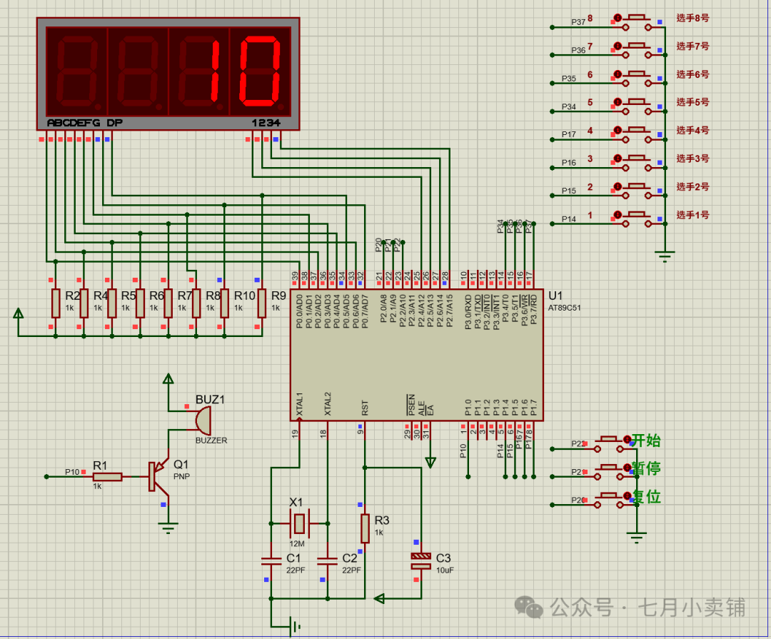
The entire system is centered around the AT89C51 microcontroller, combined with oscillators, resistors, capacitors, etc., to form the minimum system of the microcontroller. The system schematic is shown in Figure 3.1.
System Input: The input signals of the buzzer come from two parts: one is the host controlling the buzzer through control buttons in the key module, time setting button, and reset button; the other is the eight contestants inputting through the buzzer buttons in the key module. The normal operation of the system relies on the 5V voltage input provided by the power supply module.
System Output: The buzzer outputs sound and light through the buzzer module and digital display module. When there is a violation or a need for a reminder, the buzzer sounds; contestant buzzing, violations, and countdown information are displayed through the four-digit common cathode digital display.
3.1.2 System Block Diagram
The system block diagram is shown in Figure 3.2, the eight-way buzzer consists of five modules. The minimum system of the microcontroller is at the core, containing the AT89C51 microcontroller, oscillator circuit, and reset circuit; the input part includes contestant key buzzer module, host control module, and power module; the output part consists of digital display module and buzzer alarm module.
3.2 Minimum System Design of the Microcontroller
3.2.1 AT89C51 Microcontroller
(1) Features of the Microcontroller
The microcontroller is a microcomputer that integrates the CPU, memory ( RAM/ROM), I/O interfaces, timers, interrupt systems, and other functions on a single semiconductor silicon chip. Microcontrollers are small, low-cost, easy to use, and stable and reliable, promoting research and progress in electronic devices. Users can design systems centered around microcontrollers based on their needs, combined with peripheral interface circuits and peripherals, and write corresponding programs to achieve measurement and control functions.
(2) Overview of the AT89C51 Microcontroller
AT89C51RC is a low-power, high-performance CMOS 8-bit microcontroller produced by STC Company, equipped with 8KB of programmable Flash memory, compatible with traditional 8051 microcontrollers, supporting 12 clock/machine cycles and 6 clock/machine cycle selections. Compared to the AT89C51, the STC microcontroller provides a larger 512 byte data storage space and 2K byte EEPROM storage space, with stronger anti-interference capability and good cost-performance ratio.
(3) Pin Function of the 8051 Microcontroller
The AT89C51 microcontroller adopts 40 pins, with 32 external bidirectional I/O ports, 3 16-bit timers, and 2 full-duplex serial communication ports. The pin layout is shown in Figure 3.5.
Power Pins
VCC (Pin 40): Connect to +5V power supply.
GND (Pin 20): Ground.
Clock Pins
XTAL1 (Pin 19): Connect to an external crystal or clock source.
XTAL2 (Pin 18): Connect to an external crystal or leave unconnected.
Control Pins
RESET (Pin 9): Reset signal input, high level effective.
ALE (Pin 30): Provides low 8-bit address latch signal.
Parallel I/O Port Pins
P0 Port: Open-drain bidirectional I/O port, used for expanding external memory and I/O interfaces.
The digital display module circuit uses a four-digit common cathode digital display, utilizing dynamic scanning to light up the display, as shown in Figure 3.11. The microcontroller outputs segment codes to the I/O (P0.0 to P0.7) ports, and controls the digit selection lines of the digital display through I/O (P2.4 to P2.7) to achieve dynamic scanning display.
3.6 Power Supply Module Design
The power supply module consists of a power socket J1 and a control switch SW1, as shown in Figure 3.12. It uses a +5V DC power supply, supporting power banks, phone chargers, computer USB interfaces, and other devices.
Chapter 4 System Software Design
4.1 Programming Language and Development Environment
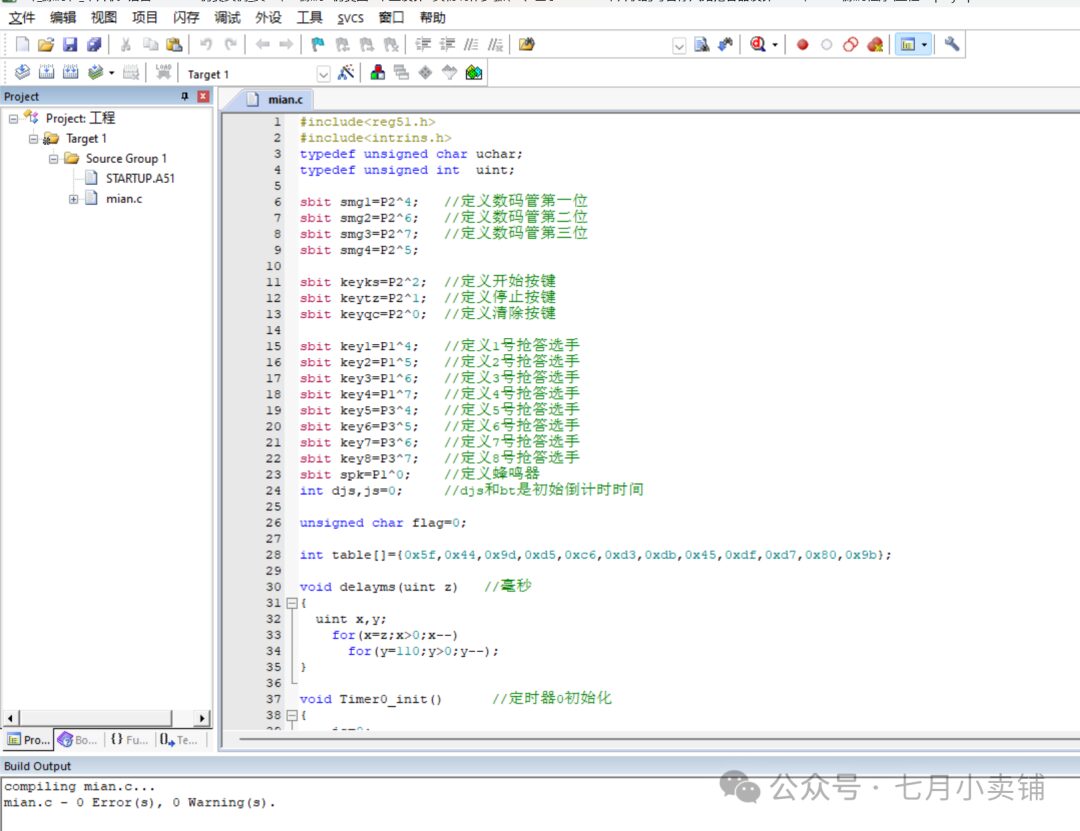
This software design is conducted in the Keil uVision4 development environment, using C language to write programs to realize the basic functions of the eight-way buzzer.C language is a widely used high-level programming language suitable for system software and application software development. It has become one of the most popular procedural programming languages due to its concise syntax, rich operators, and efficient execution speed.
The programming process in C includes editing source code, compiling, linking the target program, and running the executable program. Compared to other programming languages, C offers higher flexibility and freedom, with fewer syntax restrictions, making it suitable for various complex application development.
Keil uVision4 is a development tool specifically designed for microcontroller programming, supporting programming in C language. The software provides a rich set of library functions and powerful compilation and debugging tools, efficiently generating target code, simplifying the development process, allowing programmers to implement functionality more quickly.
4.2 Program Flow Design
4.2.1 Overall Program Design
The overall design flowchart of the eight-way buzzer is shown in Figure 4.1. The system program design involves multiple key program modules, including the 8 contestant key scanning program, EEPROM setting program, question time setting program, delay program, and the service programs of the two timers (Timer 0 and Timer 1) of the AT89C51 microcontroller. In particular, the program also includes the dynamic scanning program for the four-digit digital display and a 50ms timing program.
At the beginning of the program writing, necessary header files are introduced, initial values for registers are set, and pins for the buzzer, digital display, keys, etc., are defined. Next, the timers are initialized in sequence, and the programs for the buzzer, question, and buzzer time setting, as well as the service programs for Timer 0 and Timer 1, are written, and finally, the main function is written.
After initializing the microcontroller, the program enters a main loop, as shown in Figure 4.1. First, the host can determine whether to set the buzzer time and question time. If not set, the host can configure it through the setting button; if set, it enters the question answering process. Before the host presses the start buzzer button, the program will monitor whether any contestant buzzes. If a contestant buzzes, the buzzer will sound, and the digital display will show violation information and contestant number; if no contestant buzzes, the system will remain in standby mode, waiting for the host’s command. Once the start buzzer button is pressed, the system will enter the buzzer time countdown. If no contestant buzzes in the last 5 seconds, the buzzer will continue to sound, indicating the time is up, and the current round of buzzing ends; if a contestant buzzes during the countdown, the system will switch to the question time countdown. During the question time countdown, the program will check whether only 5 seconds are left; if so, the buzzer will start sounding; if the question time reaches 0, buzzing will stop, and the digital display will show “—-“, the buzzer will sound, and the current round of questions ends.
4.2.2 Dynamic Scanning Program for Digital Display
This design adopts the dynamic scanning method for the digital display, by writing a program to control the microcontroller to light up the four-digit display in sequence, with a brief delay. Since each digit’s lighting time is only 2 milliseconds, the switching speed is very fast, and the human eye cannot perceive it, so it uses the visual persistence effect to make it appear as if the four-digit display is lit simultaneously. The dynamic scanning flowchart of the digital display is shown in Figure 4.2.
4.2.3 Time Setting Program
To facilitate adjusting the buzzer time and question time based on actual conditions, a manual time setting program is designed. Users can modify the time through the time setting button. During the writing process, the buzzer time button and question time button are combined into one, optimizing the interface design and saving hardware space. At the same time, the original functions of contestant buzzer buttons seven and eight were modified to be used for time increment and decrement in time setting mode. The specific design flow is shown in Figure 4.3.
In the initial state, when the referee presses the time setting button, the system enters the buzzer time setting mode, and the digital display shows “E-30” (30 being the preset buzzer time). During this process, the program will check whether keys seven and eight are pressed: if key seven is pressed and the displayed time is greater than 0, the time will decrease; if key eight is pressed and the displayed time is less than 99, the time will increase. After completing the buzzer time setting, pressing the setting button again will enter the question time setting mode, where the digital display shows “F-15” (15 being the preset question time). This process is similar to the buzzer time setting, using the buttons to adjust the time.
To facilitate adjusting the buzzer time and question time of the designed eight-way buzzer based on actual conditions, a manual time setting program was compiled using the C language assembly software. Users can modify the time through the time setting button according to the actual answering rules on-site. In the software writing process, the buzzer time button and question time button were merged into one for convenience and space-saving. Additionally, the original functions of contestant buzzer buttons seven and eight were modified to allow for time decrement and increment in time setting mode. The specific design flow is shown in Figure 4.3 Time Program Flowchart.
In the initial state, when the referee presses the time setting button, it first enters the buzzer time setting mode, while the digital display shows “E-30” (30 being the preset buzzer time). In this process, it first checks whether keys seven and eight are pressed; if key seven is pressed and the displayed time is greater than 0, the time can be decreased; otherwise, the time remains unchanged; if key eight is pressed and the displayed time is less than 99, the time can be increased; otherwise, it stays the same. After modifying the buzzer time, pressing the setting button again will enter the question time setting mode, displaying “F-15” (15 being the preset question time). This process is similar to the buzzer time setting process, both using the buttons for time adjustments. After setting the question time, pressing the time setting button again will return to the initial state, and the digital display will show “0000”.
4.3 System Program Debugging
The program for the eight-way buzzer system designed this time is written in C language and compiled and debugged using keil4 software. The main function serves as the core, sequentially calling the digital display function, 8 contestant buzzer functions, buzzer functions, and delay functions. After compilation and simulation, ensure the program is correct. After writing the program, it needs to be saved and compiled; if errors occur, locate the error position according to the arrow display, and make the necessary modifications. After making changes, save and compile again until the message “0 Error” appears. Additionally, the compilation results often come with warnings; if there are no specific requirements, these warnings can be ignored.
Chapter 5 System Simulation
5.1 System Simulation Software
The Proteus simulation software is a powerful EDA tool developed by Lab Center Electronics in the UK. It not only has simulation functions of general EDA software but also allows inputting programs into microcontrollers for simulation of the microcontroller and its peripheral circuits.
Proteus software implements a complete simulation from schematic layout, code loading into the microcontroller and peripheral circuits, and even allows switching to PCB design, forming an integrated design process. The software has over twenty thousand simulation devices, provides rich stimulus sources, has intuitive simulation displays, and includes complete PCB design functions, including compilation and debugging. These features make Proteus one of the most commonly used schematic simulation software today.
5.2 Schematic Simulation
After opening the Proteus software, based on the schematic created by DXP, users can search for the relevant components needed to build the eight-way buzzer in the component library (by clicking the “P” key on the left) and select similar components, as shown in Figure 5.1.
After completing the component selection, place the components in the corresponding positions according to the schematic, connect each pin by drawing wires, and finally add power and ground. To ensure successful simulation, the system software program compiled through Keil4 needs to be written into the AT89C51 microcontroller. The specific operation is to double-click the microcontroller icon, select the “Program File” option, and import the program file Project.hex into the microcontroller.
Next, users can enter the simulation experiment by clicking the “Start Simulation” button in the lower left corner. If there are no errors during the simulation, and the schematic can simulate normally, all expected functions can be achieved. For example, after starting the buzzer, the scenario where contestant number 3 successfully buzzes and enters the question countdown is shown in Figure 5.2. During the pause, the lighting of the digital display also indicates that the display operates in a dynamic scanning manner. After debugging all the functions, users can click the “End” button.
6. Physical Welding and Debugging
6.1 Component List
The main components of this eight-way buzzer design include: AT89C51 microcontroller, oscillator, resistors, capacitors, keys, switches, power socket, transistors, buzzers, and digital displays, etc. Among them, the oscillator uses 12MHz, and the capacitors are two 30pF and one 10μF. The resistor used in the circuit is 10K, which needs to be measured with a multimeter to ensure that the actual product is consistent with the theoretical design. The specific component list is shown in Table 6.1.
Table
Component NameQuantity
AT89C51 microcontroller1
Oscillator1
ResistorSeveral
Capacitors3
KeysSeveral
Switches1
Power Socket1
TransistorsSeveral
Buzzers1
Digital Displays4
6.2 Circuit Board Welding
During the circuit board welding process, the order of inserting components should follow the principle of “first small, then large; first low, then high,” meaning welding smaller components first, then larger ones. Ensure the distribution of components is clear and orderly, with a beautiful overall appearance and strong practicality. For polarized components, they must be installed according to the installation requirements on the schematic to avoid incorrect installation. During welding, avoid cold soldering and missed soldering, and the soldering iron should not stay on the circuit board for too long to prevent burning components and the circuit board. At the same time, the soldering iron’s temperature should be kept appropriate; too high or too low temperatures can lead to poor soldering.
6.3 Physical Debugging
After welding is completed, carefully check the physical welding circuit against the schematic to ensure proper and complete placement of components, and that the wiring connections are correct. Use a multimeter to measure the resistance across the resistor and apply power to the buzzer to check if it operates normally.
After confirming everything is correct, use the Keil4 development environment to compile and debug the software program using the learned C language, and then use the Proteus simulation software to combine the software and hardware to realize the functions of the eight-way buzzer. Finally, compare the welded physical product with the designed schematic to obtain the finished product. Throughout these processes, it was not smooth sailing; there were issues such as finding suitable resistors and capacitors during schematic design and insufficient understanding of the microcontroller, but these were ultimately resolved through consultation with teachers and reference materials. The innovation of this design is the addition of a time setting module. By summarizing this design and reflecting on it, a scoring module could also be added to display the scores of contestants.
This design marks a perfect conclusion to my four years of university study. Reflecting on these four years, I have learned a lot about microcontrollers, assembly language, and other knowledge. Through this graduation design, I not only deepened my mastery of what I learned but also promoted my learning of new knowledge, making my application of knowledge more solid and benefiting me greatly.