Let’s take a look at how to create a “hollow clock” with only hands and no dial using Arduino.
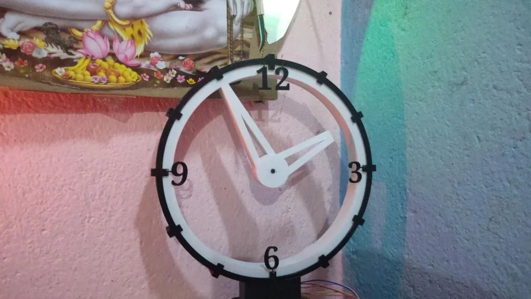
It looks quite cool, and here are some images shared by users who followed the tutorial:
Step 0: Material Preparation
- 28BYJ-48 stepper motor and driver board
- Microcontroller for controlling the stepper motor (e.g., Arduino Nano)
- 2mm x 10mm self-tapping screws * 8
- Grease (high viscosity)
This clock can be printed with most common 200 x 200mm printers, except for the decorative part (index.stl, 203 x 203mm).
At the end of the article, there is also a smaller version (85%).
Step 1: Print Parts
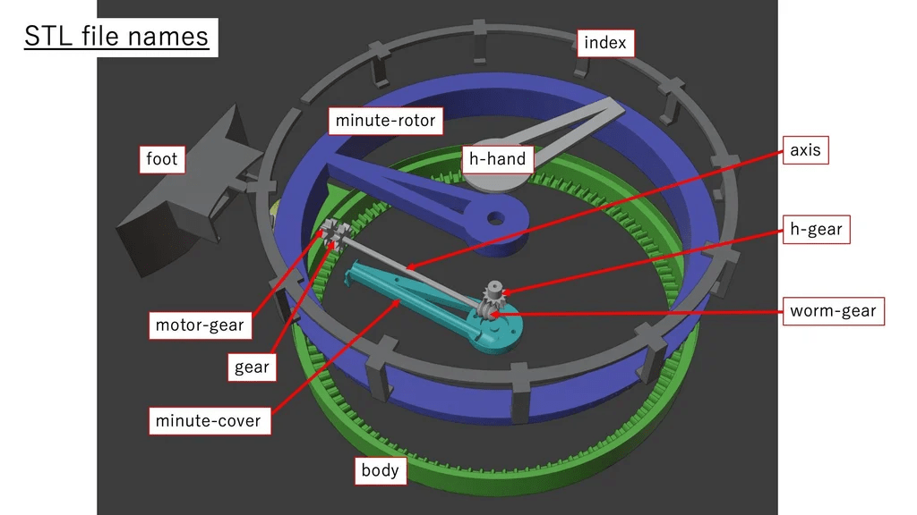
- Print the parts
- Some parts require supports
- Deburr carefully, especially for the very small gears (the worm gear and small gear at the center of the clock)
Step 2: Assemble the Worm Gear Drive System
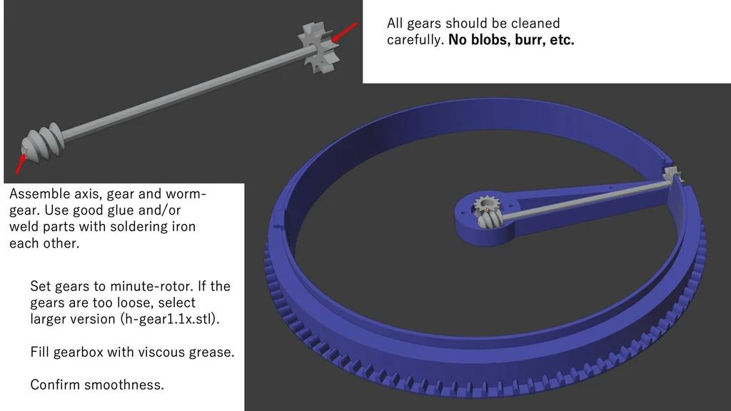
- Use a soldering iron for plastic welding to connect
gear.stl,axis.stl, andworm-gear.stl. - You can also use some safe glue, such as two-component epoxy.
- Inject a little grease into the central gear. This not only reduces friction but also minimizes backlash.
- The backlash in the central gear significantly affects the clock’s accuracy.
h-gear1.1x.stlis slightly larger than the originalh-gear.stlto suppress backlash. Choose the better small gear from the two candidates.
Step 3: Assemble the Motor Driver
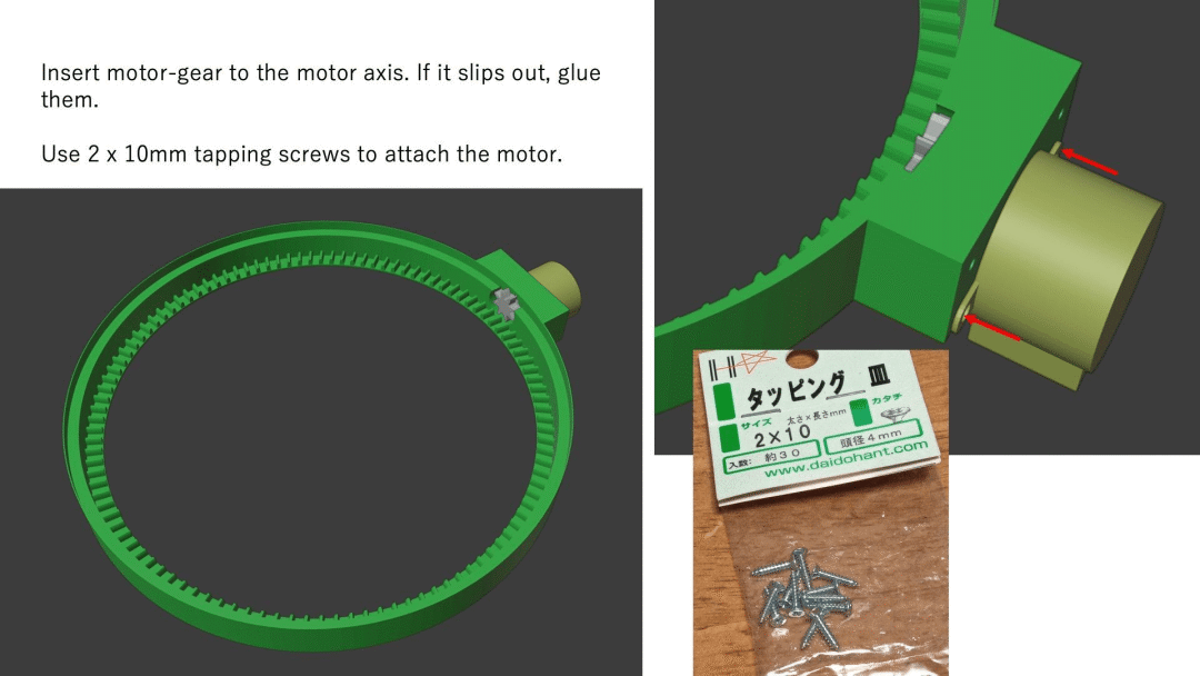
- If the head of the 2mm self-tapping screw is smaller than the hole of the stepper motor, use washers or replace it with larger screws.
Step 4: Engage the Minute Rotor with the Clock Body
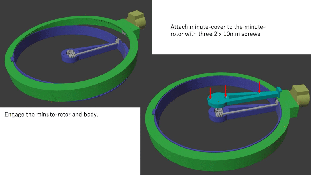
- To prevent the gears from falling off, we can flip one side of the body (the green part in the image above) and hook the top.
- Three self-tapping screws are needed to install the minute cover.
Step 5: Install the Hour Hand
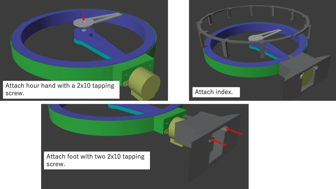
- Be careful not to tighten the self-tapping screw too much when installing the hour hand; it should be able to slide when you adjust the clock.
- Secure the other parts.
Step 6: Prepare the Circuit
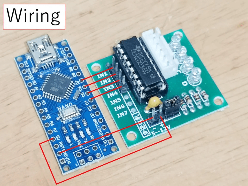
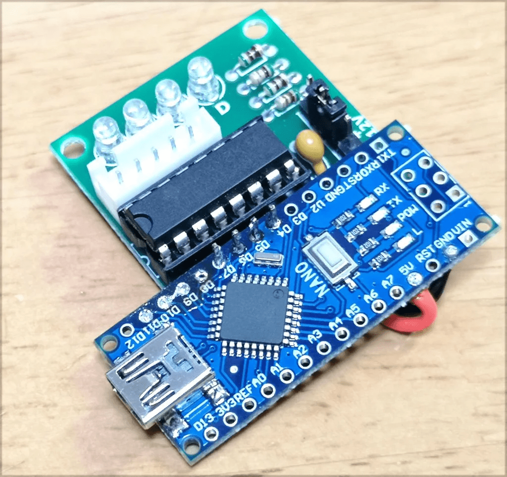
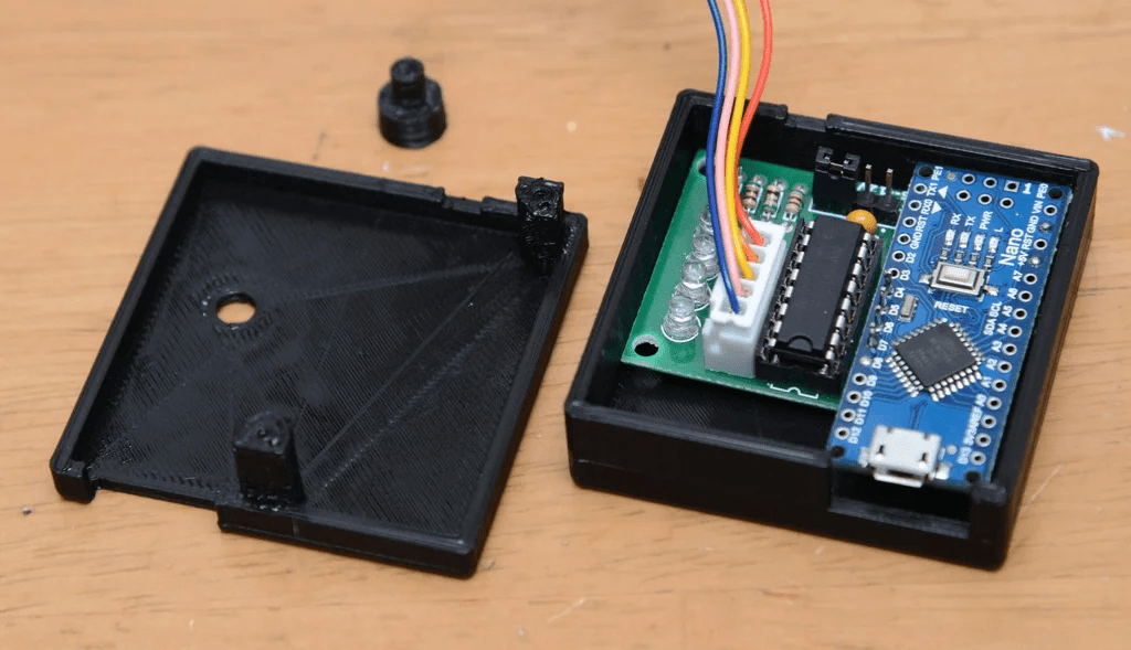
- Connect ports 4, 5, 6, and 7 of the Nano to the stepper motor driver.
- Connect VCC (+5V) and GND.
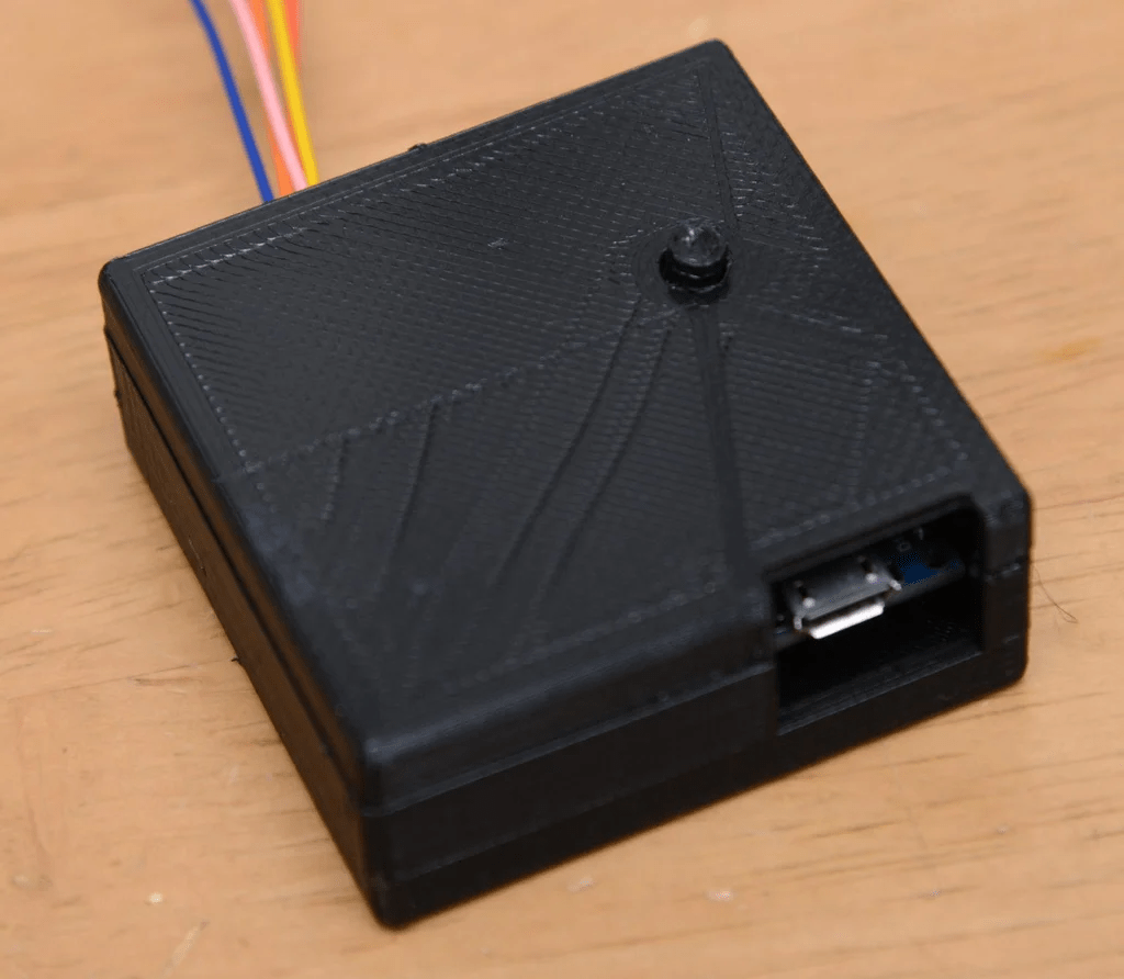
If you want to enclose the entire circuit in a box, you can print parts to make a box (related files are at the end of the article).
Then assemble it with two 2mm self-tapping screws.
Step 7: Programming
Upload the code to the Arduino. Flash the code onto the Arduino IDE.
If your motor runs in the wrong direction, modify the order of the numbers in the code:
int port[4] = {4, 5, 6, 7};Change it to:
int port[4] = {7, 6, 5, 4};The above numbers correspond to the pins on the Arduino Nano (D4-D7).
The complete code is as follows:
// Please tune the following value if the clock gains or loses.// Theoretically, standard of this value is 60000.#define MILLIS_PER_MIN 60000 // milliseconds per a minute
// Motor and clock parameters// 4096 * 110 / 8 = 56320#define STEPS_PER_ROTATION 56320 // steps for a full turn of minute rotor
// wait for a single step of stepperint delaytime = 2;
// ports used to control the stepper motor// if your motor rotate to the opposite direction, // change the order as {4, 5, 6, 7};int port[4] = {4, 5, 6, 7};
// sequence of stepper motor controlint seq[8][4] = {  {  LOW, HIGH, HIGH,  LOW},  {  LOW,  LOW, HIGH,  LOW},  {  LOW,  LOW, HIGH, HIGH},  {  LOW,  LOW,  LOW, HIGH},  { HIGH,  LOW,  LOW, HIGH},  { HIGH,  LOW,  LOW,  LOW},  { HIGH, HIGH,  LOW,  LOW},  {  LOW, HIGH,  LOW,  LOW}};
void rotate(int step) {static int phase = 0;int i, j;int delta = (step > 0) ? 1 : 7;int dt = 20;
  step = (step > 0) ? step : -step;for(j = 0; j < step; j++) {    phase = (phase + delta) % 8;for(i = 0; i < 4; i++) {      digitalWrite(port[i], seq[phase][i]);    }    delay(dt);if(dt > delaytime) dt--;  }// power cutfor(i = 0; i < 4; i++) {    digitalWrite(port[i], LOW);  }}void setup() {  pinMode(port[0], OUTPUT);  pinMode(port[1], OUTPUT);  pinMode(port[2], OUTPUT);  pinMode(port[3], OUTPUT);  rotate(-20); // for approach run  rotate(20); // approach run without heavy load  rotate(STEPS_PER_ROTATION / 60);}void loop() {static long prev_min = 0, prev_pos = 0;long min;static long pos;
  min = millis() / MILLIS_PER_MIN;if(prev_min == min) {return;  }  prev_min = min;  pos = (STEPS_PER_ROTATION * min) / 60;  rotate(-20); // for approach run  rotate(20); // approach run without heavy load  rotate(pos - prev_pos);  prev_pos = pos;}
Step 8: Testing and Adjusting
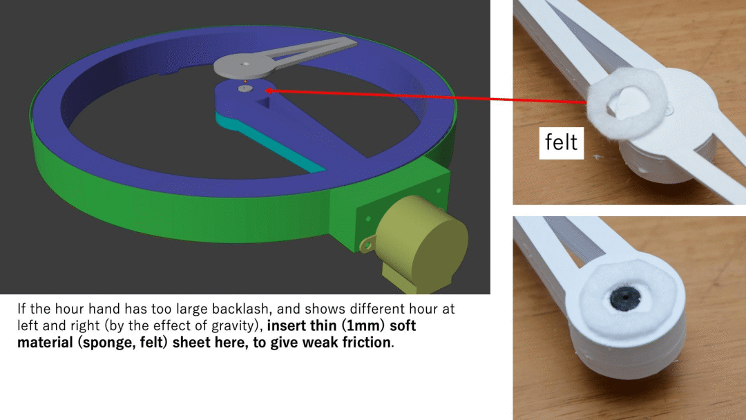
- Due to the backlash in the gear set, the position of the hour hand may deviate to the left or right. To solve this problem, you can insert some soft material, like felt or sponge, to provide some friction.
- Painting the hands can improve visibility. Paint-type coatings are better than dye-type inks, which can cause capillary diffusion.
Step 9: Time Adjustment
- Use the reset button on the Nano to set the time forward by one minute.
- While the motor is rotating, use the reset button for fine-tuning.
- The hour hand can be adjusted directly by hand (due to friction).
Source: https://www.instructables.com/Hollow-Clock-3/ Author: shiura