Click the blue text to follow us
In the digital world, DIY projects are always full of infinite charm, and the ESP32-S2 chip brings endless creative inspiration to geeks. Today, let’s dive into a super interesting project—creating a multifunctional USB keyboard and mouse device using the ESP32-S2! With just an ESP32-S2 core board, an expansion board, and some simple code, you can transform ordinary joysticks and buttons into powerful tools for controlling a computer mouse and keyboard. Not only can you flexibly control the mouse pointer with the joystick, but you can also input specific characters with a single button, achieving efficient operations with ease. Come join us to unlock new ways to play with the ESP32-S2 and start your geek journey!
01
Project Introduction
This project is developed using the Arduino framework, based on the USBHID extension library, to implement the ESP32-S2 as a composite USB keyboard and mouse device. The joystick on the expansion board controls the mouse movement, while one button acts as the left mouse button, and another button automatically inputs the string “eetree.cn”.
02
Design Concept
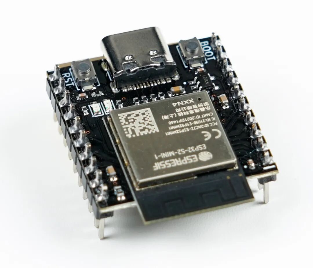
The ESP32 core board provided by HardWare is the ESP32-S2-MINI-1, which integrates a USB TYPE-C interface. When connected to a computer via this USB interface, it can simulate being recognized as a keyboard and mouse through USBHID, allowing the input devices on the expansion board to simulate keyboard and mouse control.
In the Arduino ESP32 examples, there is an example called KeyboardAndMouseControl. Based on this example and the requirements of this project, specific functionalities were implemented:
1.Simulate itself as a USBHID device, specifically as a composite keyboard and mouse device.
2.Read the joystick input device information from the expansion board and convert it into movements in four directions (up, down, left, right) to control the mouse movement.
3.Read the ADC button information from the expansion board to control the left mouse click and simulate keyboard input of a string.
03
Hardware Introduction
The hardware used in this project is provided by HardWare, including:
ESP32-S2 Core Board:
ESP32-S2 Expansion Board:
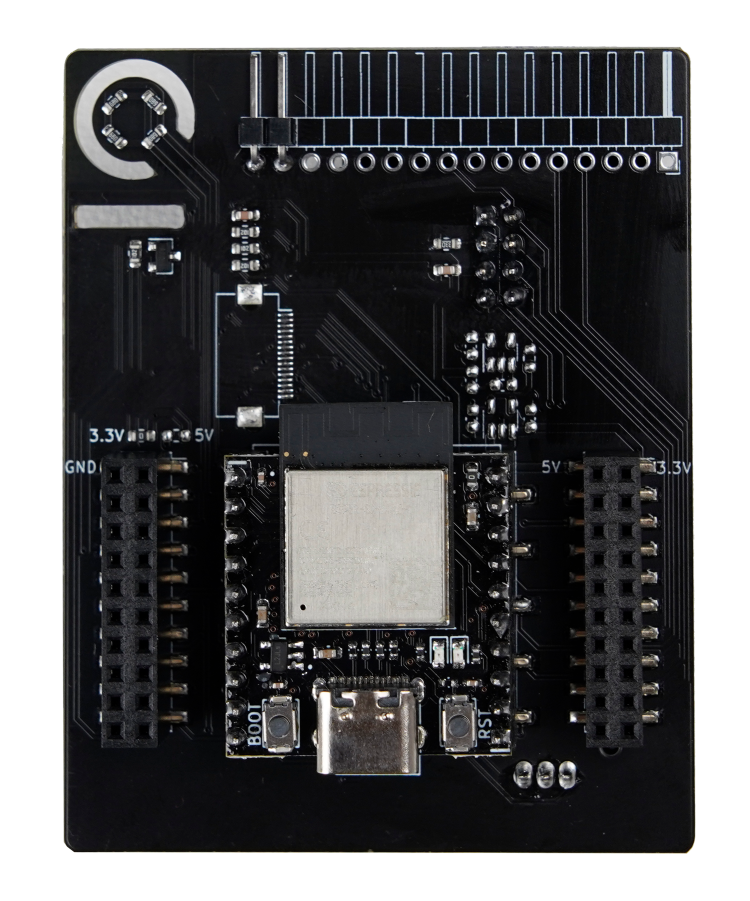
The expansion board provides a joystick device with PWM input and a button device with ADC input.
From the expansion board schematic, we can obtain specific GPIO information:
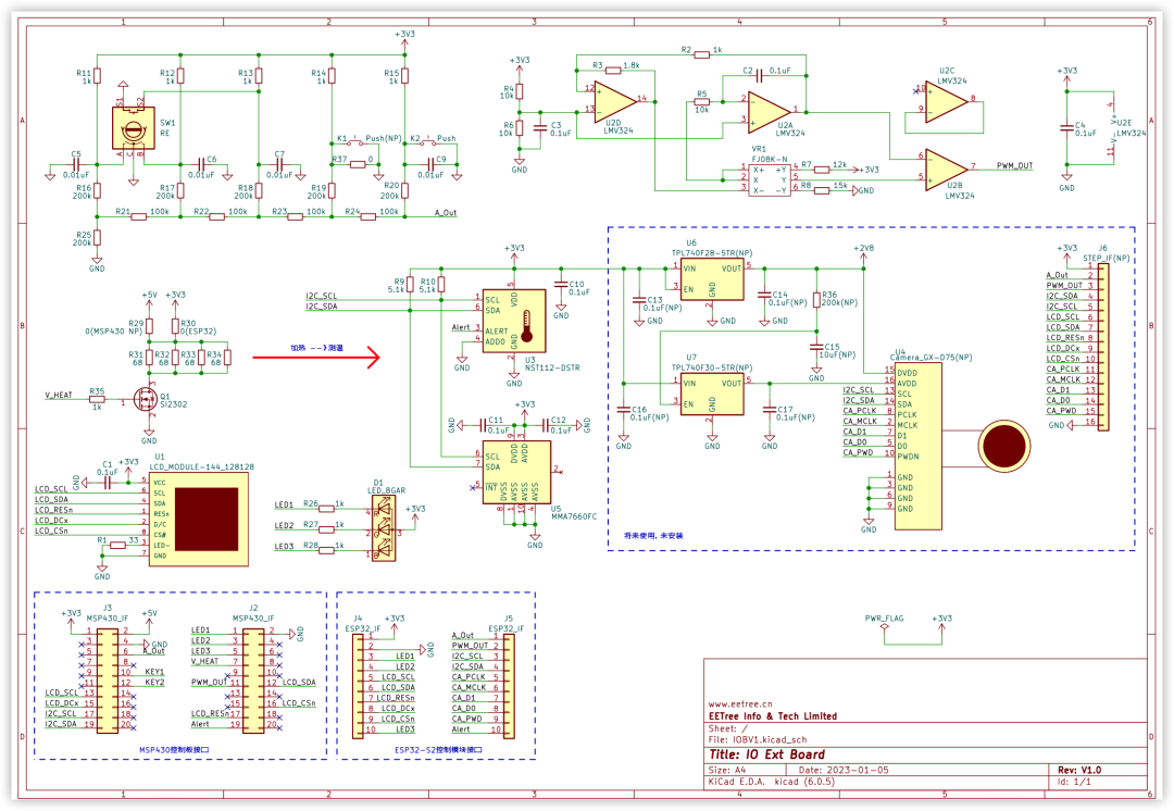
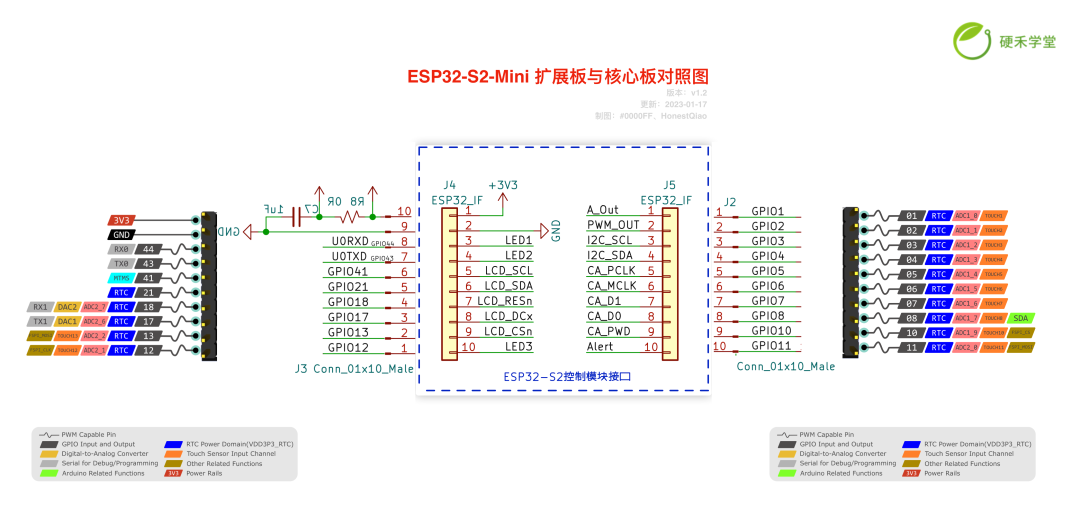
From the above, we can see:
1.The button is connected to A_OUT, corresponding to GPIO1.
2.The joystick is connected to PWM_OUT, corresponding to GPIO2.
Since the expansion board provides complete connections and control circuits for the above peripherals, no additional assistance is needed; just using the ESP32-S2 core board and the expansion board can complete all tasks.
04
Function Implementation
The ESP32-S2 can be developed in many ways, including using ESP-IDF, Arduino, micropython, and circuitpython. This project uses the Arduino framework for development.
Through Arduino, the final implemented functionalities are as follows:
1.When the device is connected to a computer, it will be recognized as an HID device, including mouse and keyboard devices.
2.When the joystick device on the expansion board is moved, the mouse pointer on the computer will correspondingly move.
3.Pressing the button on the rotary encoder will trigger the left mouse button operation.
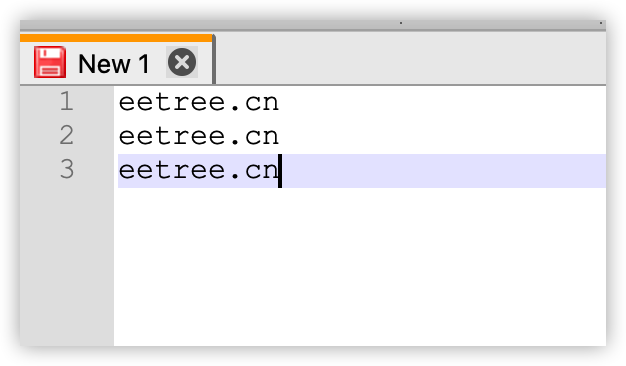
4.Pressing the K2 button will trigger keyboard operations, automatically outputting the string “eetree.cn”.
05
Code Explanation
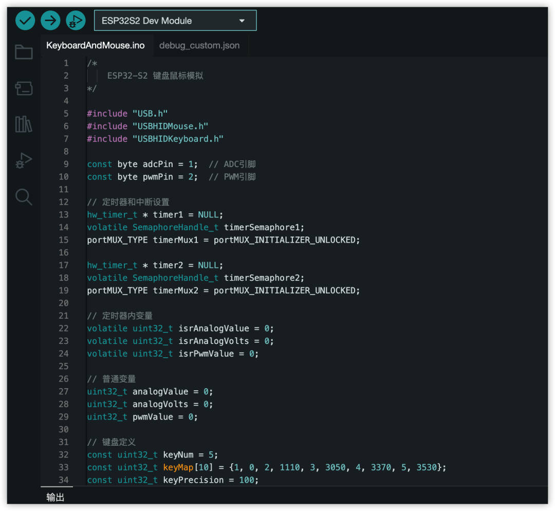
/* ESP32-S2 Keyboard and Mouse Simulation*/#include "USB.h"#include "USBHIDMouse.h"#include "USBHIDKeyboard.h"const byte adcPin = 1; // ADC pinconst byte pwmPin = 2; // PWM pin// Timer and interrupt settingshw_timer_t * timer1 = NULL;volatile SemaphoreHandle_t timerSemaphore1;portMUX_TYPE timerMux1 = portMUX_INITIALIZER_UNLOCKED;hw_timer_t * timer2 = NULL;volatile SemaphoreHandle_t timerSemaphore2;portMUX_TYPE timerMux2 = portMUX_INITIALIZER_UNLOCKED;// Timer variablesvolatile uint32_t isrAnalogValue = 0;volatile uint32_t isrAnalogVolts = 0;volatile uint32_t isrPwmValue = 0;// Normal variablesuint32_t analogValue = 0;uint32_t analogVolts = 0;uint32_t pwmValue = 0;// Keyboard definitionsconst uint32_t keyNum = 5;const uint32_t keyMap[10] = {1, 0, 2, 1110, 3, 3050, 4, 3370, 5, 3530};const uint32_t keyPrecision = 100;// Direction definitionsconst uint32_t directionNum = 4;const uint32_t directionMap[8] = {1, 2472, 2, 1170, 3, 1289, 4, 2640};const uint32_t directioPrecision = 50;// Mouse and keyboard definitionsUSBHIDMouse Mouse;USBHIDKeyboard Keyboard;void ARDUINO_ISR_ATTR onTimer1(){ portENTER_CRITICAL_ISR(&timerMux1); // ADC read isrAnalogValue = analogRead(adcPin); isrAnalogVolts = analogReadMilliVolts(adcPin); portEXIT_CRITICAL_ISR(&timerMux1); // Release semaphore xSemaphoreGiveFromISR(timerSemaphore1, NULL);}void ARDUINO_ISR_ATTR onTimer2(){ portENTER_CRITICAL_ISR(&timerMux2); // PWM read isrPwmValue = pulseIn(pwmPin, HIGH); portEXIT_CRITICAL_ISR(&timerMux2); // Release semaphore xSemaphoreGiveFromISR(timerSemaphore2, NULL);}uint32_t getKey(uint32_t val){ if (val >= 3700) { // } else { for (int i = 0; i < keyNum; i++) { if (keyMap[i*2+1] > 0 && val > keyMap[i*2+1]-keyPrecision && val < keyMap[i*2+1] + keyPrecision) return keyMap[i*2]; } } return 0;}uint32_t getDirection(uint32_t val){ if (val >= 3700) { // } else { for (int i = 0; i < directionNum; i++) { if (directionMap[i*2+1] > 0 && val > directionMap[i*2+1]-directioPrecision && val < directionMap[i*2+1] + directioPrecision) return directionMap[i*2]; } } return 0;}void setup(){ Serial.begin (115200); Serial.println (); Mouse.begin(); Keyboard.begin(); USB.begin(); // Create semaphore timerSemaphore1 = xSemaphoreCreateBinary(); timerSemaphore2 = xSemaphoreCreateBinary(); // Timer 1 settings timer1 = timerBegin(0, 80, true); // Start timer timerAttachInterrupt(timer1, &onTimer1, true); // Set interrupt callback timerAlarmWrite(timer1, 100000, true); // Set short period to 1000000-1s // Timer 2 settings timer2 = timerBegin(1, 80, true); // Start timer timerAttachInterrupt(timer2, &onTimer2, true); // Set interrupt callback timerAlarmWrite(timer2, 100000, true); // Set short period to 1000000-1s // Enable timers timerAlarmEnable(timer1); // Enable timer delay(50); timerAlarmEnable(timer2); // Enable timer // Set ADC resolution, 2^12, 4096 analogReadResolution(12); // Set PWM input pinMode(pwmPin, INPUT);}void loop(){ // Check ADC semaphore if (xSemaphoreTake(timerSemaphore1, 0) == pdTRUE){ // Get data from interrupt portENTER_CRITICAL(&timerMux1); analogValue = isrAnalogValue; analogVolts = isrAnalogVolts; portEXIT_CRITICAL(&timerMux1); // Output // Serial.printf("analogValue=%d analogVolts=%d\n", analogValue, analogVolts); uint32_t key = getKey(analogValue); if(key) { Serial.print(analogValue); Serial.print(" "); Serial.println(key); switch(key) { case 2: // K2 button //Keyboard.write('2'); Keyboard.print("eetree.cn"); delay(300); break; case 3: // Left mouse button Mouse.click(MOUSE_LEFT); delay(100); break; } } }// Check PWM semaphore if (xSemaphoreTake(timerSemaphore2, 0) == pdTRUE){ // Get data from interrupt portENTER_CRITICAL(&timerMux2); pwmValue = isrPwmValue; portEXIT_CRITICAL(&timerMux2); // Output //Serial.printf("pwmVal=%d\n", pwmValue); uint32_t direction = getDirection(pwmValue); if(direction) { Serial.print(pwmValue); Serial.print(" "); Serial.println(direction); switch(direction) { case 1: // Mouse left move Mouse.move(-40, 0); break; case 2: // Mouse up move Mouse.move(0, -40); break; case 3: // Mouse right move Mouse.move(40, 0); break; case 4: // Mouse down move Mouse.move(0, 40); break; } } }}<code>In the above code, three supporting libraries are called:
1.USB.h: USB support
2.USBHIDMouse.h: USB mouse support
3.USBHIDKeyboard: USB keyboard support
Since the joystick is a PWM input, the code defines the PWM input information corresponding to each direction of the joystick:
// Direction definitionsconst uint32_t directionNum = 4;const uint32_t directionMap[8] = {1, 2472, 2, 1170, 3, 1289, 4, 2640};const uint32_t directioPrecision = 50;Four directions are set with a tolerance range of 50.
Since the buttons use ADC input, the code defines the ADC input information corresponding to each button:
// Keyboard definitionsconst uint32_t keyNum = 5;const uint32_t keyMap[10] = {1, 0, 2, 1110, 3, 3050, 4, 3370, 5, 3530};const uint32_t keyPrecision = 100;To be compatible with the ESP32-S2 and MSP430 expansion boards, five buttons are defined here.
In actual use, K2 corresponds to 2, and the rotary encoder button corresponds to 3.
Additionally, a tolerance range of 100 is set for the read analog values.
To more effectively obtain data from the joystick and buttons, the code uses timers for reading, ensuring that the information retrieval is not affected by the main process code, thus improving the stability of input information acquisition.
After obtaining the button and joystick information, the code controls the actions of the keyboard and mouse based on the actual data received.
06
Operation Steps
1. Write code using Arduino IDE
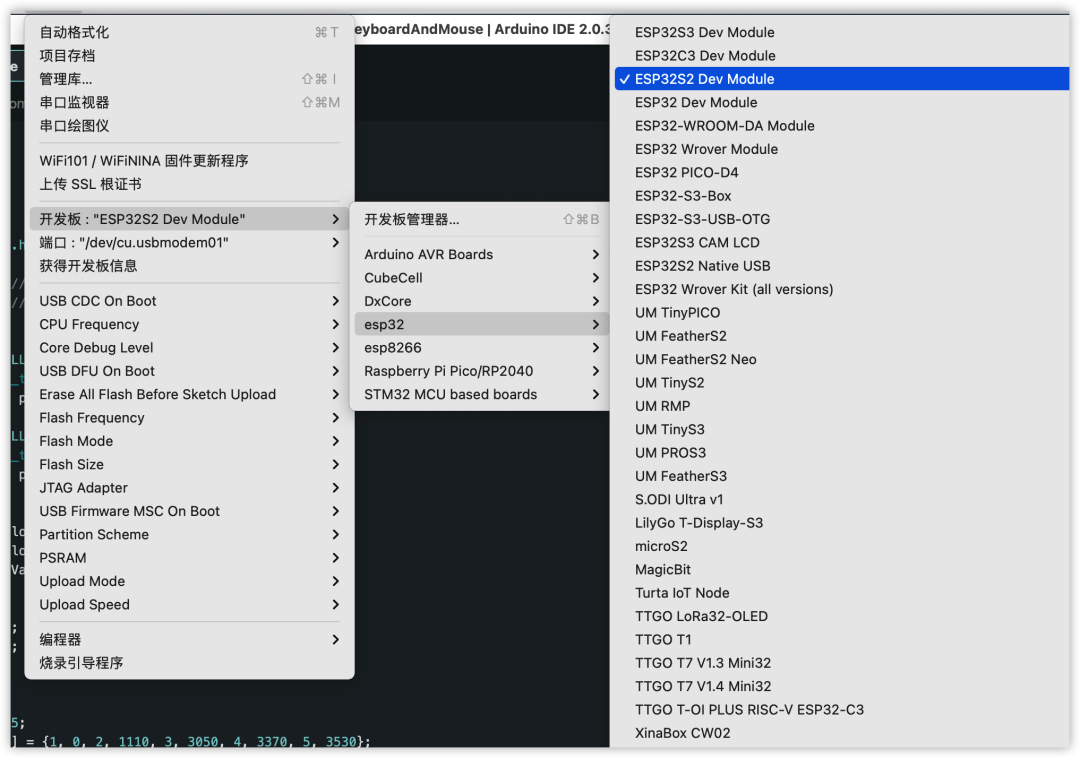
2. Set connection parameters
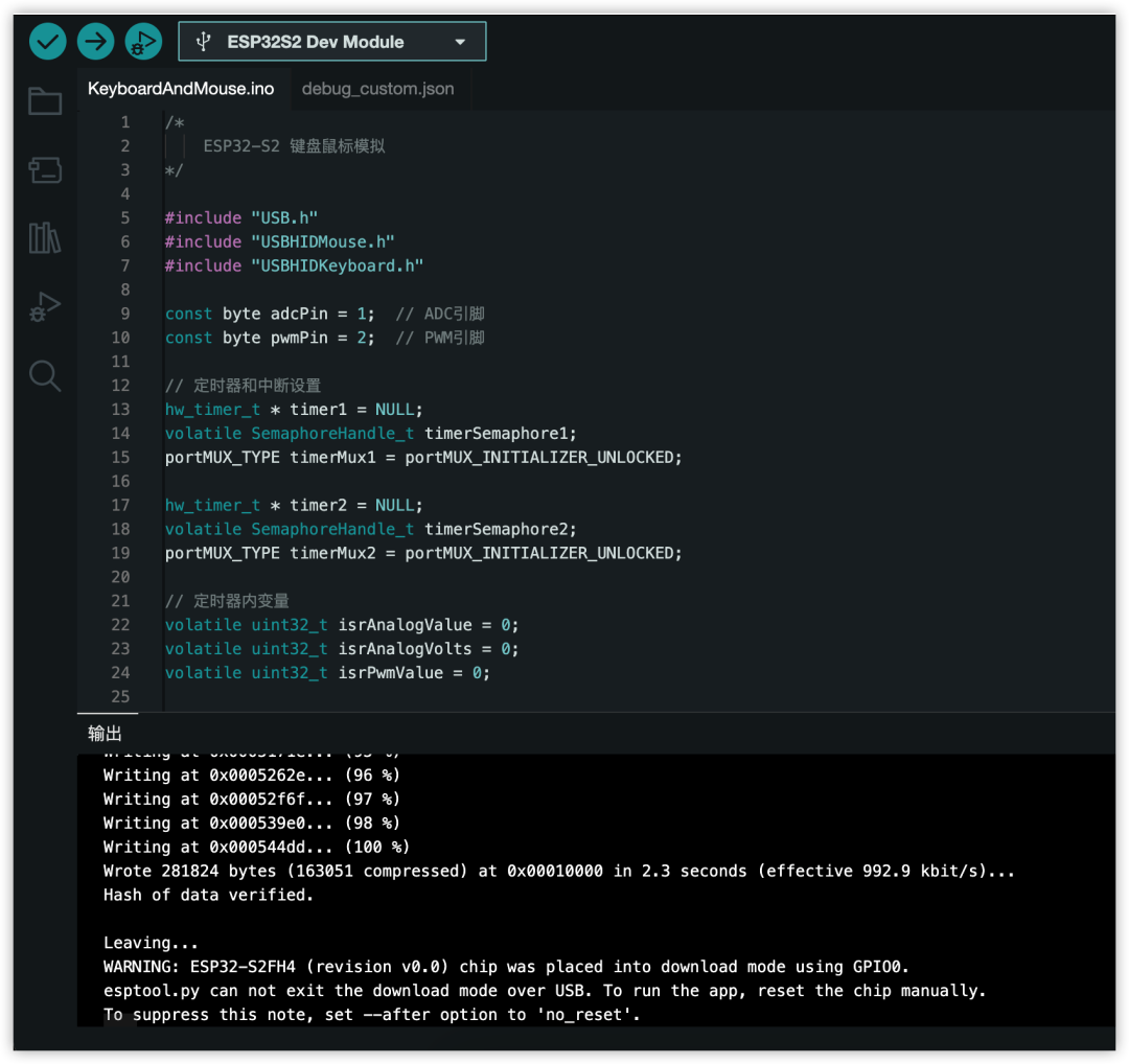
3. Compile and upload the code
4. Actual control test:
-
Move the joystick in different directions and observe the mouse movement.
-
Press K2 and observe the keyboard output.
-
Press the rotary encoder button and observe the mouse click action.

Click “Read the original text” to view the project.