Quality article, delivered on time
First, let’s present the mind map of this article
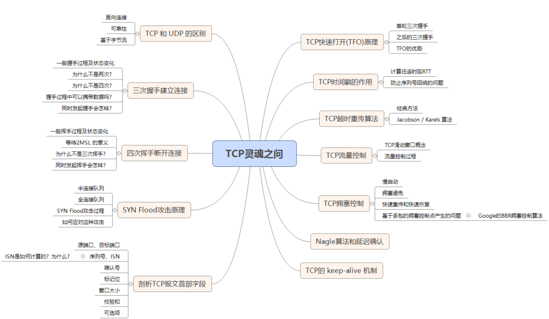
TCP, as a protocol of the transport layer, is a reflection of a software engineer’s quality and is often a topic of discussion in interviews. Here, I have sorted out some core issues related to TCP to help everyone.
001. Can you talk about the differences between TCP and UDP?
First, let’s summarize the basic differences:
TCP is a connection-oriented, reliable, byte-stream-based transport layer protocol.
While UDP is a connectionless transport layer protocol. (It’s that simple, other features of TCP are not applicable here).
Specifically analyzing, compared to UDP, TCP has three core characteristics:
-
Connection-oriented. The so-called connection refers to the connection between the client and the server. Before both parties communicate with each other, TCP needs to establish a connection through a three-way handshake, while UDP does not have a corresponding connection establishment process.
-
Reliability. TCP goes to great lengths to ensure the reliability of the connection. What does this reliability manifest in? One is stateful, and the other is controllable.
TCP accurately records which data has been sent, which data has been received by the other party, and which has not been received, ensuring that packets arrive in order without any errors. This is stateful.
When it realizes that packets are lost or the network environment is poor, TCP adjusts its behavior according to the specific situation, controlling its sending speed or retransmitting. This is controllable.
Correspondingly, UDP is stateless and uncontrollable.
- Byte-stream oriented. UDP transmits data based on datagrams, which merely inherits the characteristics of the IP layer, while TCP converts individual IP packets into a byte stream to maintain state.
002: Can you explain the process of TCP’s three-way handshake? Why three times instead of two or four?
Love Simulation
Taking a romantic relationship as an example, the most important thing for two people to be together is to first confirm each other’s ability to love and to be loved. Now let’s simulate the three-way handshake process based on this.
First time:
Male: I love you.
Female receives it.
This proves that the male has the ability to love.
Second time:
Female: I received your love, and I love you too.
Male receives it.
OK, the current situation indicates that the female has both the ability to love and be loved.
Third time:
Male: I received your love.
Female receives it.
Now it can be guaranteed that the male has the ability to be loved.
This fully confirms both parties’ love and be loved abilities, and they begin a sweet relationship.
Real Handshake
Of course, the above is just a joke and does not represent my values; the purpose is to help everyone understand the significance of the entire handshake process, as the two processes are very similar. Corresponding to TCP’s three-way handshake, it also needs to confirm two abilities of both parties: sending ability and receiving ability. Thus, the following three-way handshake process occurs:
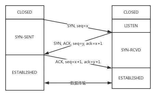
Initially, both parties are in the CLOSED state. Then the server starts listening on a certain port and enters the LISTEN state.
Then the client actively initiates the connection, sending SYN, and changes its state to SYN-SENT.
The server receives it, returns SYN and ACK (corresponding to the SYN sent by the client), and changes its state to SYN-REVD.
Then the client sends ACK back to the server, changing its state to ESTABLISHED; after the server receives ACK, it also changes to ESTABLISHED state.
Another thing to remind you is that from the diagram, it can be seen that SYN consumes a sequence number; the next time the corresponding ACK sequence number should be incremented by 1. Why? Just remember one rule:
Any packet that requires acknowledgment from the other party will consume a TCP packet’s sequence number.
SYN requires acknowledgment from the other party, while ACK does not, so SYN consumes a sequence number while ACK does not.
Why not two times?
The fundamental reason: it cannot confirm the client’s receiving ability.
Analysis as follows:
If it were two times, you sent a SYN packet to initiate the handshake, but this packet is stuck in the current network and has not arrived for a long time. TCP thinks this is a lost packet and retransmits it, establishing the connection with two handshakes.
It seems there’s no problem, but after the connection is closed, if this stuck packet in the network arrives at the server, what would happen? Since it is a two-way handshake, the server will just assume that the connection is established once it receives it and sends the corresponding data packet, but now the client has already disconnected.
Do you see the problem? This leads to a waste of connection resources.
Why not four times?
The purpose of the three-way handshake is to confirm the sending and receiving abilities of both parties. So can it be done with four handshakes?
Of course, it can be done with 100 times. But to solve the problem, three times is sufficient; any more would not be very useful.
Can data be carried during the three-way handshake?
During the third handshake, data can be carried. The first two handshakes cannot carry data.
If the first two handshakes could carry data, then if someone wanted to attack the server, they could just send a large amount of data in the SYN packet of the first handshake, causing the server to consume more time and memory space to process this data, increasing the risk of the server being attacked.
During the third handshake, the client is already in the ESTABLISHED state and can confirm that the server’s receiving and sending abilities are normal. At this point, it is relatively safe to carry data.
What happens if both parties open simultaneously?
If both parties send SYN packets simultaneously, what will the state changes look like?
This is a situation that may occur.
The state changes are as follows:
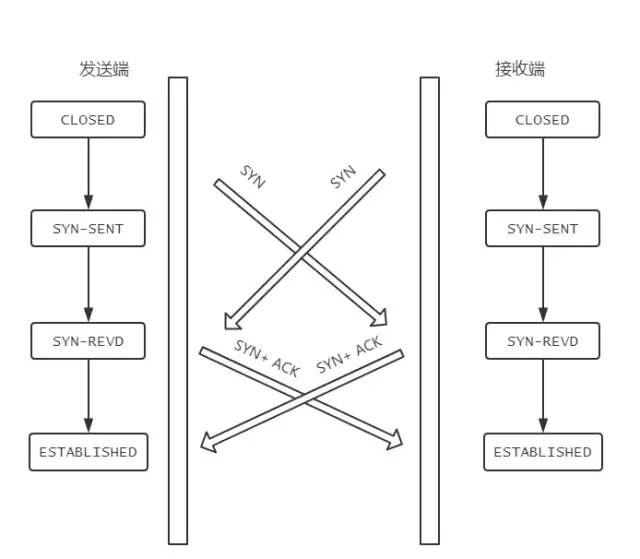
When the sender sends a SYN packet to the receiver, the receiver also sends a SYN packet to the sender at the same time, and they just started!
After sending SYN, both parties’ states change to SYN-SENT.
After each receives the other’s SYN, their states change to SYN-REVD.
Then they will respond with the corresponding ACK + SYN, and after the other party receives this packet, both states will change to ESTABLISHED.
This is the state transition in the case of simultaneous openings.
003: Can you explain the process of TCP’s four-way handshake?
Process Breakdown
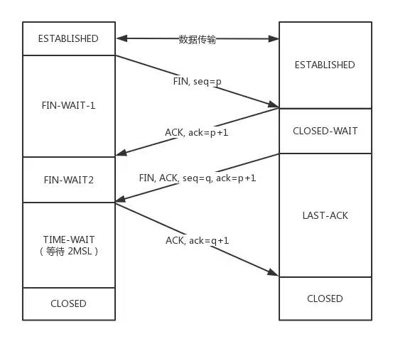
Initially, both parties are in the ESTABLISHED state.
The client wants to disconnect, sends a FIN packet to the server, and the position in the TCP packet is as shown in the figure:
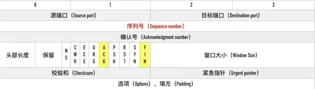
After sending, the client changes to the FIN-WAIT-1 state. Note that at this time, the client also becomes half-close, meaning it can no longer send packets to the server, only receive.
The server receives it and acknowledges it, changing to the CLOSED-WAIT state.
The client receives the server’s acknowledgment and changes to the FIN-WAIT-2 state.
Then, the server sends a FIN to the client and enters the LAST-ACK state.
The client receives the FIN sent by the server and changes to the TIME-WAIT state, then sends an ACK to the server.
Note that at this time, the client needs to wait a sufficient amount of time, specifically, for 2 MSL (Maximum Segment Lifetime), and during this time if the client does not receive a retransmission request from the server, it indicates that the ACK has successfully reached the server, ending the handshake; otherwise, the client retransmits the ACK.
Significance of Waiting 2MSL
What happens if you don’t wait?
If you don’t wait, and the client disconnects directly while the server still has many packets to send to the client, and if the client’s port happens to be occupied by a new application, then it will receive useless packets, causing packet confusion. Therefore, the safest approach is to wait until all packets sent by the server are gone before starting a new application.
Then, if one MSL is not enough, why wait for 2 MSLs?
- 1 MSL ensures that the last ACK packet sent by the active closing party ultimately reaches the other party.
- 1 MSL ensures that the FIN packet that the other party has not received ACK for can reach.
This is the significance of waiting for 2MSL.
Why four handshakes instead of three?
Because the server often does not immediately return FIN after receiving FIN, it must wait until all packets have been sent before sending FIN. Therefore, it first sends an ACK to indicate that it has received the client’s FIN, and after a delay, it sends FIN. This results in four handshakes.
If it were three handshakes, what problems would arise?
It would mean that the server has combined the sending of ACK and FIN into one handshake, which might lead to long delays causing the client to mistakenly think that FIN has not reached the client, thus leading the client to continuously retransmit FIN.
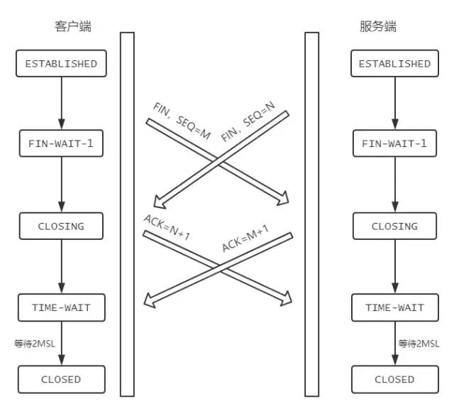
What happens if both close simultaneously?
If both the client and server send FIN simultaneously, how will the states change? As shown in the figure:
004: Can you explain the relationship between half-connection queues and SYN Flood attacks?
Before the three-way handshake, the server’s state changes from CLOSED to LISTEN, while internally creating two queues: half-connection queue and full-connection queue, namely SYN queue and ACCEPT queue.
Half-connection Queue
When the client sends SYN to the server, after the server receives it, it replies with ACK and SYN, changing its state from LISTEN to SYN_RCVD. At this point, this connection is pushed into the SYN queue, which is the half-connection queue.
Full-connection Queue
When the client returns ACK, after the server receives it, the three-way handshake is complete. At this point, the connection waits to be taken by a specific application, and before it is taken, it will be pushed into another queue maintained by TCP, which is the full-connection queue (Accept Queue).
SYN Flood Attack Principle
SYN Flood is a typical DoS/DDoS attack. The principle of the attack is very simple: it uses the client to forge a large number of nonexistent IP addresses within a short time and crazily sends SYN to the server. For the server, this will result in two dangerous consequences:
-
Handling a large number of
SYNpackets and returning correspondingACK, will inevitably cause many connections to be in theSYN_RCVDstate, filling the entire half-connection queue, making it impossible to process normal requests. -
Since it is nonexistent IPs, the server will not receive the client’s
ACKfor a long time, leading the server to keep retransmitting data until the server’s resources are exhausted.
How to respond to SYN Flood attacks?
- Increase SYN connections, i.e., increase the capacity of the half-connection queue.
- Reduce the number of SYN + ACK retransmissions to avoid a large number of timeout retransmissions.
- Use SYN Cookie technology: after the server receives
SYN, do not immediately allocate connection resources, but calculate a Cookie based on thisSYN, and return it along with the second handshake to the client. When the client replies withACK, it carries thisCookievalue, and the server allocates connection resources only after verifying the legality of the Cookie.
005: Can you introduce the fields in the TCP packet header?
The structure of the packet header is as follows (in bytes):
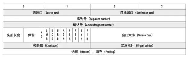
Please remember this image!
Source Port, Destination Port
How to uniquely identify a connection? The answer is the TCP connection’s four-tuple—source IP, source port, destination IP, and destination port.
So why doesn’t the TCP packet have source IP and destination IP? This is because the IP layer has already handled the IP. TCP only needs to record the ports of both parties.
Sequence Number
That is Sequence number, which refers to the sequence number of the first byte of this segment.
From the image, we can see that the sequence number is a 4-byte long unsigned integer, with a range of 0 ~ 2^32 – 1. If it reaches the maximum value, it cycles back to 0.
The sequence number has two functions during TCP communication:
- Exchanging each other’s initial sequence numbers in the SYN packet.
- Ensuring that packets are assembled in the correct order.
ISN
That is Initial Sequence Number. During the three-way handshake, both parties will exchange their ISN through SYN packets.
The ISN is not a fixed value; it increments every 4 ms, and when it overflows, it returns to 0. This algorithm makes it difficult to guess the ISN. Why do this?
If the ISN is predicted by an attacker, knowing both the source IP and source port number is easy to forge. Once the attacker guesses the ISN, they can directly forge a RST packet to forcibly close the connection, which is very dangerous.
Dynamic growth of the ISN greatly increases the difficulty of guessing it.
Acknowledgment Number
That is ACK (Acknowledgment number). It is used to inform the other party of the next expected sequence number, indicating that all bytes less than ACK have been received.
Flags
Common flags include SYN, ACK, FIN, RST, PSH.
SYN and ACK have been discussed earlier; the latter three are explained as follows: FIN: Finish, indicating that the sender is ready to disconnect.
RST: Reset, used to forcibly disconnect the connection.
PSH: Push, informing the other party that these packets should be delivered to the upper layer application immediately and should not be cached.
Window Size
It occupies two bytes, which is 16 bits, but in practice, it is not enough. Therefore, TCP introduces the window scaling option, as a scaling factor for window size, with a range of 0 ~ 14, which can expand the window value to 2 ^ n times the original.
Checksum
It occupies two bytes and prevents packet damage during transmission. If a packet with a checksum error is encountered, TCP discards it directly and waits for retransmission.
Options
The format of options is as follows:

Common options include:
- TimeStamp: TCP timestamp, to be detailed later.
- MSS: Maximum Segment Size that TCP allows receiving from the other party.
- SACK: Selective Acknowledgment option.
- Window Scale: Window scaling option.
006: Can you explain the principle of TCP Fast Open (TFO)?
The first section talked about TCP’s three-way handshake. Some may say, isn’t it cumbersome to do a three-way handshake every time? Can it be optimized a bit?
Yes, today we will discuss the optimized TCP handshake process, which is the principle of TCP Fast Open (TFO).
The optimization process is as follows: remember the SYN Cookie mentioned when discussing SYN Flood attacks? This cookie is not the same as the browser’s Cookie, and it can also be used to implement TFO.
TFO Process
First Round Three-way Handshake
First, the client sends SYN to the server, and the server receives it.
Note! Now the server does not immediately reply with SYN + ACK, but calculates a SYN Cookie, places this Cookie in the TCP packet’s Fast Open option, and then returns to the client.
The client caches this Cookie value. Then it completes the three-way handshake normally.
This is the process of the first round of the three-way handshake. The subsequent three-way handshake is different!
Subsequent Three-way Handshake
In the subsequent three-way handshake, the client sends the previously cached Cookie, SYN, and HTTP request (yes, you read that correctly) to the server. The server verifies the legality of the Cookie; if it is invalid, it is discarded; if it is valid, it returns SYN + ACK normally.
The key point is that now the server can send HTTP responses to the client! This is the most significant change; the three-way handshake has not yet been established, and merely verifying the legality of the Cookie allows the server to return HTTP responses.
Of course, the client’s ACK must still be transmitted normally; otherwise, how can it be called a three-way handshake?
The process is as follows:
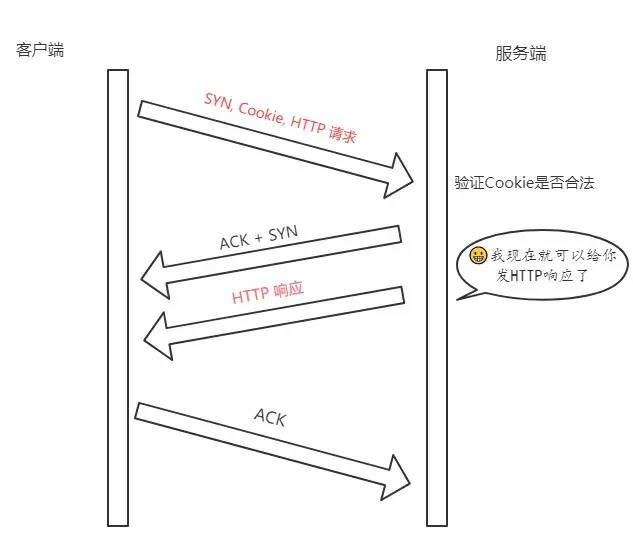
Note: The client’s final handshake ACK does not necessarily have to wait for the server’s HTTP response to arrive before sending; the two processes are unrelated.
Advantages of TFO
The advantage of TFO is not in the first round of the three-way handshake but in the subsequent handshake. After obtaining and verifying the client’s Cookie, the server can directly return HTTP responses, fully utilizing 1 RTT (Round-Trip Time) for early data transmission, which accumulates to be a significant advantage.
007: Can you talk about the role of timestamps in TCP packets?
timestamp is an optional field in the TCP packet header, occupying a total of 10 bytes, formatted as follows:
kind(1 byte) + length(1 byte) + info(8 bytes)Where kind = 8, length = 10, and info consists of two parts: timestamp and timestamp echo, each occupying 4 bytes.
What are these fields for? What problems do they solve?
Next, we will outline the two main issues that TCP timestamps primarily address:
- Calculating Round-Trip Time (RTT)
- Preventing sequence number wraparound issues
Calculating Round-Trip Time (RTT)
When there are no timestamps, calculating RTT encounters the following problems:
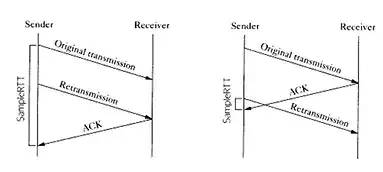
If the time of the first packet sent is taken as the start time, the left diagram shows the problem of RTT being obviously too large; the start time should use the second packet’s time;
If the second packet’s time is taken as the start time, the right diagram shows the problem of RTT being obviously too small; the start time should use the first packet’s time.
In fact, whether the start time is based on the first packet or the second packet, it is inaccurate.
At this time, introducing timestamps can effectively solve this problem.
For instance, if a sends a packet s1 to b, and b replies with a packet s2 containing an ACK, then:
- step 1: When
asends tob, thetimestampcontains the kernel timestampta1ofa‘s host. - step 2: When
breplies with packets2, thetimestampcontainsb‘s host’s timestamptb, and thetimestamp echofield containsta1extracted from packets1. - step 3: When
areceivesb‘s packets2, at this time,a‘s host’s kernel timestamp ista2, and in thetimestamp echooption in packets2, it can obtainta1, which is the initial sending time of packets2. Then, directly usingta2 - ta1gives the value of RTT.
Preventing Sequence Number Wraparound Issues
Now let’s simulate this problem.
The range of sequence numbers is actually from 0 to 2 ^ 32 – 1. For ease of demonstration, let’s shrink this range to 0 to 4, so when it reaches 4, it wraps around to 0.
| Packet Number | Sent Bytes | Corresponding Sequence Number | Status |
|---|---|---|---|
| 1 | 0 ~ 1 | 0 ~ 1 | Successfully Received |
| 2 | 1 ~ 2 | 1 ~ 2 | Stuck in Network |
| 3 | 2 ~ 3 | 2 ~ 3 | Successfully Received |
| 4 | 3 ~ 4 | 3 ~ 4 | Successfully Received |
| 5 | 4 ~ 5 | 0 ~ 1 | Successfully Received, Sequence Number Starts from 0 |
| 6 | 5 ~ 6 | 1 ~ 2 | ??? |
Assuming that during the sixth transmission, the previously stuck packet in the network returns, there will be two packets with the same sequence number 1 ~ 2. How do we distinguish between them? This creates a sequence number wraparound issue.
Using timestamps can effectively solve this problem because each time a packet is sent, the kernel time of the sending machine is recorded in the packet. Therefore, even if two packets have the same sequence number, their timestamps cannot be the same, allowing us to distinguish between the two packets.
008: How is the TCP timeout retransmission time calculated?
TCP has a timeout retransmission mechanism, meaning that if no response is received for a certain period, the packet is retransmitted.
So how is this retransmission interval calculated?
Today we will discuss this issue.
This retransmission interval is also called Retransmission TimeOut (RTO), and its calculation is closely related to the RTT mentioned in the previous section. Here we will introduce two main methods: one is the classic method, and the other is the standard method.
Classic Method
The classic method introduces a new concept—SRTT (Smoothed Round Trip Time), and every time a new RTT occurs, SRTT is updated based on a certain algorithm. Specifically, the calculation is as follows (initial value of SRTT is 0):
SRTT = (α * SRTT) + ((1 - α) * RTT)Where α is the smoothing factor, with a recommended value of 0.8 and a range of 0.8 ~ 0.9.
Once we have SRTT, we can calculate the value of RTO:
RTO = min(ubound, max(lbound, β * SRTT))Where β is a weighting factor, generally between 1.3 ~ 2.0, lbound is the lower bound, and ubound is the upper bound.
This algorithm process is relatively simple but does have certain limitations. It performs well in stable RTT environments but poorly in environments with significant RTT variation, as the smoothing factor α has a range of 0.8 ~ 0.9, making RTT’s influence on RTO too small.
Standard Method
To address the classic method’s insensitivity to RTT changes, a standard method was later introduced, also known as the Jacobson/Karels algorithm.
It consists of three steps.
Step 1: Calculate SRTT, with the formula:
SRTT = (1 - α) * SRTT + α * RTTNote that the value of α is different from that in the classic method; the recommended value is 1/8, or 0.125.
Step 2: Calculate RTTVAR (Round-Trip Time Variation), this intermediate variable:
RTTVAR = (1 - β) * RTTVAR + β * (|RTT - SRTT|)β has a recommended value of 0.25. This value is the highlight of this algorithm, meaning it records the difference between the latest RTT and the current SRTT, providing a means to perceive RTT changes in the future.
Step 3: Calculate the final RTO:
RTO = µ * SRTT + ∂ * RTTVARµ has a recommended value of 1, and ∂ has a recommended value of 4.
This formula adds the latest RTT’s offset to the base of SRTT, thus effectively perceiving changes in RTT, making RTO more closely related to RTT variations.
009: Can you discuss TCP’s flow control?
For both the sender and receiver, TCP needs to place the data sent into the send buffer and the data received into the receive buffer.
Flow control aims to manage the sender’s sending rate based on the size of the receiving buffer. If the receiving buffer is full, no further sending can occur.
To understand flow control, one must first grasp the concept of the sliding window.
TCP Sliding Window
TCP sliding windows are divided into two types: send window and receive window.
Send Window
The structure of the sender’s sliding window is as follows:
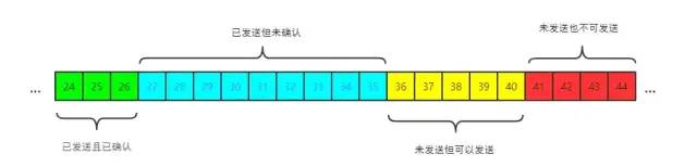
It consists of four main parts:
- Sent and acknowledged
- Sent but unacknowledged
- Not sent but can be sent
- Not sent and cannot be sent
Some important concepts are marked in the image:
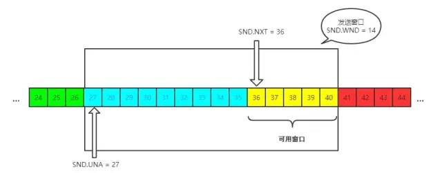
The send window is the range marked in the image. SND means send, WND means window, UNA means unacknowledged, indicating unacknowledged packets, and NXT means next, indicating the next sending position.
Receive Window
The structure of the receiver’s window is as follows:
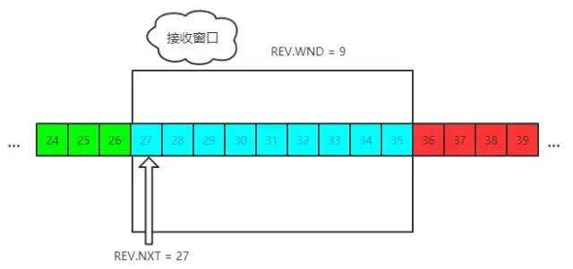
REV means receive, NXT indicates the next receiving position, and WND indicates the size of the receive window.
Flow Control Process
Here we will simulate the flow control process with a simple example for easy understanding.
First, both parties perform a three-way handshake, initializing their window sizes to 200 bytes.
Assuming the sender sends 100 bytes to the receiver, at this point, the sender’s SND.NXT will move right by 100 bytes, meaning the current available window decreases by 100 bytes, which is easy to understand.
Now these 100 bytes arrive at the receiver and are placed in the receiver’s buffer queue. However, due to high load, the receiver can only process 40 bytes, leaving 60 bytes in the buffer queue.
At this point, the receiver is unable to handle the load, so it needs the sender to send less data. Therefore, the receiver’s window should shrink, specifically reducing by 60 bytes, changing from 200 bytes to 140 bytes, as there are still 60 bytes that the application has not yet taken away.
Thus, the receiver will include the reduced sliding window of 140 bytes in the ACK packet header, and the sender will correspondingly adjust the size of its send window to 140 bytes.
For the sender, the amount sent and acknowledged increases by 40 bytes, meaning SND.UNA moves right by 40 bytes, while the send window shrinks to 140 bytes.
This is the flow control process. Regardless of the number of rounds, the entire control process and principle are the same.
010: Can you discuss TCP’s congestion control?
The flow control discussed in the previous section occurs between the sender and receiver, without considering the impact of the entire network environment. If the current network is particularly poor and prone to packet loss, the sender should pay attention. This is precisely what congestion control needs to address.
For congestion control, each TCP connection needs to maintain two core states:
- Congestion Window (cwnd)
- Slow Start Threshold (ssthresh)
The algorithms involved are:
- Slow Start
- Congestion Avoidance
- Fast Retransmit and Fast Recovery
Next, we will break down these states and algorithms one by one, starting with the congestion window.
Congestion Window
The congestion window (cwnd) refers to the amount of data that can currently be transmitted.
Now, the previously introduced receive window concept, what is the difference between the two?
- The receive window (rwnd) is the limit set by the
receiver - The congestion window (cwnd) is the limit set by the
sender
What does it limit?
It limits the size of the send window.
With these two windows, how is the send window calculated?
Send Window Size = min(rwnd, cwnd)It takes the smaller of the two. Congestion control is used to manage the changes in cwnd.
Slow Start
When you first start transmitting data, you do not know whether the network is stable or congested. If you act too aggressively and send packets too quickly, it can lead to massive packet loss and a network disaster.
Therefore, congestion control must first adopt a conservative algorithm to gradually adapt to the entire network, which is called Slow Start. The operation process is as follows:
- First, during the three-way handshake, both sides announce their receive window sizes.
- Both sides initialize their congestion window (cwnd) sizes.
- During the initial transmission period, for each ACK received, the congestion window size increases by 1, meaning that for each RTT, cwnd doubles. If the initial window is 10, then after the first round of sending 10 packets and receiving ACKs, cwnd becomes 20, then 40, 80, and so on.
Does this mean it can keep doubling endlessly? Of course not. Its threshold is called Slow Start Threshold. When cwnd reaches this threshold, it’s like hitting the brakes—don’t increase so fast, hold on!
After reaching the threshold, how is the size of cwnd controlled?
This is what congestion avoidance does.
Congestion Avoidance
Originally, for each ACK received, cwnd increased by 1; now that it has reached the threshold, cwnd can only increase by 1 / cwnd. If you calculate carefully, after one RTT, upon receiving cwnd ACKs, the final size of the congestion window cwnd increases by only 1.
In other words, previously cwnd doubled in one RTT, now cwnd only increases by 1.
Of course, Slow Start and Congestion Avoidance work together; they are one entity.
Fast Retransmit and Fast Recovery
Fast Retransmit
During TCP transmission, if packet loss occurs, meaning the receiver finds that data segments are not arriving in order, the receiver’s response is to repeatedly send the previous ACK.
For instance, if the 5th packet is lost, even if the 6th and 7th packets arrive at the receiver, the receiver will return ACK for the 4th packet. When the sender receives three duplicate ACKs, it realizes that packet loss has occurred and immediately retransmits it without waiting for a RTO timeout.
This is Fast Retransmit, which resolves the question of whether to retransmit.
Selective Acknowledgment
Now you might ask, since retransmission is necessary, should only the 5th packet be retransmitted, or should the 5th, 6th, and 7th packets all be retransmitted?
Of course, since the 6th and 7th packets have already arrived, TCP designers are not foolish. Why retransmit what has already been sent? Instead, they will record which packets have arrived and which have not, and retransmit accordingly.
After receiving the sender’s packet, the receiver replies with an ACK packet, and in the optional field of this packet, it can add the SACK attribute, informing the sender of which ranges of data packets have been received. Thus, even if the 5th packet is lost, after receiving the 6th and 7th packets, the receiver will still inform the sender that these two packets have arrived. The remaining 5th packet has not arrived, so it will be retransmitted. This process is also called Selective Acknowledgment (SACK), which addresses the question of how to retransmit.
Fast Recovery
After the sender receives three duplicate ACKs and realizes that packet loss has occurred, it perceives that the network is congested and will enter the Fast Recovery phase.
During this phase, the sender makes the following changes:
- The congestion threshold is reduced to half of cwnd.
- cwnd is set to the congestion threshold.
- cwnd increases linearly.
This is the classic algorithm for TCP congestion control: Slow Start, Congestion Avoidance, Fast Retransmit and Fast Recovery.
011: Can you discuss the Nagle algorithm and delayed acknowledgment?
Nagle Algorithm
Imagine a scenario where the sender continuously sends very small packets to the receiver, sending only 1 byte at a time. To send 1000 bytes, it would require 1000 transmissions. This frequent sending poses problems; not only does it consume transmission delay, but the sending and acknowledgment processes also take time, leading to significant delays.
The Nagle algorithm aims to avoid the frequent sending of small packets.
Specifically, the rules of the Nagle algorithm are as follows:
- When the first piece of data is sent, it is sent immediately without waiting, even if it is a 1-byte small packet.
- Subsequent transmissions can occur when one of the following conditions is met:
- The packet size reaches the maximum segment size (MSS).
- All previous packets’ ACKs have been received.
Delayed Acknowledgment
Now consider a scenario where I receive a packet from the sender and shortly afterward receive a second packet. Should I reply to each one individually, or should I wait a bit and combine the ACKs for both packets before replying?
Delayed acknowledgment does the latter; it waits briefly, combines the ACKs, and then replies to the sender. TCP requires that this delay must be less than 500 ms, and most operating system implementations do not exceed 200 ms.
However, it is important to note that there are some scenarios where delayed acknowledgment cannot be applied:
- When a packet larger than one frame is received and the window size needs adjustment.
- When TCP is in quick acknowledgment mode (set by
tcp_in_quickack_mode). - When out-of-order packets are detected.
What happens when both are used together?
The former means delaying sending, while the latter means delaying receiving, which can lead to greater delays and performance issues.
012. How to understand TCP’s keep-alive?
Everyone has heard of HTTP’s keep-alive, but TCP also has a keep-alive mechanism, which differs somewhat from the application layer.
Imagine a scenario where one party becomes disconnected due to network failure or downtime. Since TCP is not a polling protocol, the other party is unaware of the connection failure until the next data packet arrives.
This is where keep-alive comes in; its purpose is to probe whether the other party’s connection has failed.
In Linux, you can check related configurations like this:
sudo sysctl -a | grep keepalive
// Check every 7200 s
net.ipv4.tcp_keepalive_time = 7200
// A maximum of 9 packets can be retransmitted
net.ipv4.tcp_keepalive_probes = 9
// Each packet retransmission interval is 75 s
net.ipv4.tcp_keepalive_intvl = 75
However, the reality is that most applications do not have the TCP keep-alive option enabled by default. Why?
From the application’s perspective:
- 7200s (two hours) is too long to check.
- If the time is shortened, it does not effectively reflect its design intention, which is to detect long-term dead connections.
Thus, it is a rather awkward design.
Source:juejin.im/post/5e527c58e51d4526c654bf41
– END –
Previous recommendations


Spring Boot's most elegant HTTP client tool, just use this, it's so good!

Why MySQL does not recommend using UUID or snowflake ID as primary keys?

A comprehensive SQL statement collection of 15000 words

An overview of common Spring annotations

MySQL optimization implementation plan


If you like the article, click to read it.