Lai Ruiqiang
(Quanzhou Huaguang Vocational College, Quanzhou, Fujian 362121)
Abstract: With the continuous development of smart campuses, the access control system of school computer rooms is also gradually becoming intelligent. This article designs an access control system for computer rooms using NB-IoT technology. The access control system is mainly controlled by Arduino Mega2560 Pro, and adopts the NB-IoT communication method. The system uses a fingerprint recognition module to identify personnel; it uses a relay to control the electromagnetic lock’s opening and closing; it uses an LCD display to show information such as fingerprint enrollment and temporary authorization code input. Battery voltage and identity recognition information are transmitted to the Dandeng Technology platform through NB-IoT, achieving remote monitoring. When temporary access is needed, the administrator can log into the Dandeng Technology platform (or APP) to remotely unlock.
Keywords: NB-IoT; Access Control System; Fingerprint Recognition; Remote Monitoring; LCD Display; Dandeng Technology
Classification Number: TP391.44; TP273 Document Identification Code: A
Article Number: 2095-1302 (2022) 10-0084-03
With the continuous development of technologies such as narrowband IoT, smart campuses are also rapidly developing. A smart campus is a campus management system that integrates big data, the Internet of Things, and the Internet. The “Smart Campus Overall Framework” (GB/T 36342—2018) clearly states that the smart campus is a further development and enhancement of digital entry into campuses and is a higher form of educational informatization [1]. The standard points out that the perception system in the infrastructure layer should include device perception and personnel identity recognition. The computer room is an important teaching area in schools, and the security, convenience, and management methods of traditional computer room access control systems can no longer meet the intelligent needs of smart campuses. Therefore, it is necessary to upgrade and transform the computer room access control system.
Currently, ordinary computer room access control still uses simple mechanical locks, and traditional computer room access control requires dedicated personnel to operate. With the continuous development of smart campuses, traditional management methods are no longer suitable for current campuses [2]. This article designs an intelligent access control system for computer rooms using NB-IoT technology, which can provide convenience for computer room management staff and improve management efficiency. This system replaces traditional mechanical locks with electromagnetic locks; it uses a fingerprint recognition module to identify personnel, and the recognition results are displayed on the LCD display. At the same time, the recognition information is transmitted to the Dandeng Technology platform via the NBIoT module, allowing management personnel to log into the platform to view recognition information. The identity recognition results are displayed on the screen and can also be played through a voice broadcast module; fingerprint enrollment can be achieved through the matrix keyboard’s key switching function. When unauthorized individuals need to enter the computer room, management personnel can unlock remotely or enter a temporary authorization code through the matrix keyboard.
1 Overall System Design Scheme
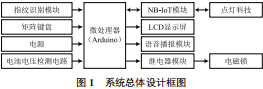
The computer room access control system uses Arduino Mega2560 Pro as the main controller, including a fingerprint recognition module for identity recognition, an NB-IoT module for data transmission, a relay electromagnetic lock module, an LCD display for information display, a matrix keyboard, a battery voltage detection circuit, and a user-friendly voice broadcast module. The overall design block diagram of the system is shown in Figure 1.
2 Terminal Hardware Design
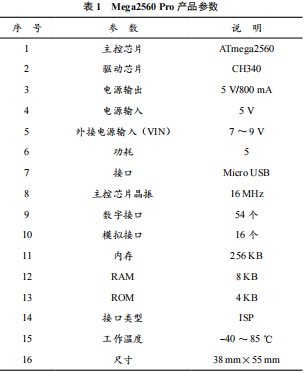
The system’s main controller adopts Arduino Mega2560 Pro. The main control board size is 38 mm×55 mm, which is smaller than the common Arduino UNO main control board; the small size of the main control board also makes the terminal size relatively small. Mega2560 Pro and the standard version Mega2560 both use the ATmega2560 (16 MHz crystal oscillator) chip, which means that these two modules have the same functionality. Mega2560 Pro has 54 digital interfaces (I/O ports), of which 15 can be used as PWM outputs. Mega2560 Pro provides 4 UART communication paths, i.e., Serial communication. Data is indicated by the ATmega 8U2/ATmega 16U2 when the indicator light flashes (except for ports 0 and 1). By utilizing the SoftwareSerial library, any digital interface of Mega2560 Pro can be used as a communication interface. The product parameters of Mega2560 Pro are listed in Table 1.
The system identifies identity, battery voltage, and other information transmitted to the IoT platform via NB-IoT. The NB-IoT module uses the NB101 module from Gu Yu IoT. NB101 is a core board based on the Quectel NB module BC95, which leads out commonly used signals, is plug-and-play, and is very convenient. It is a high-performance, low-power module [3]. The NB101 has an IPEX RF antenna seat, a 5V to 3.3V LDO voltage regulator, a MicroSIM card slot, ESD protection circuit, etc.; users can focus on the upper-level application to quickly develop products based on NB-IoT. The module has 3 working modes: wake-up (Active state), light sleep (Idle state), and deep sleep (PSM state). When the module is in the wake-up state, all functions are normal and available, allowing data transmission and reception. When the module is in light sleep state, the network is in DRX/eDRX state and can receive paging messages; when the module is in deep sleep state, only the RTC works, and the network is in a non-connected state [4].
 The commonly used interfaces of the module include 8, including the power interface VDD and GND, the module’s UART communication interfaces TXD and RXD, where the module’s TXD is the data transmission interface connected to the main controller’s RXD; the module’s RXD is the data transmission interface connected to the main controller’s TXD. Both pins are 3.0V signal levels, and when connected to a 3.3V main controller, a 1kΩ resistor must be connected in series. The LDO voltage regulator chip enable pin is EN. The module has a reset pin RESET. The module also has 2 communication indication pins: NET network status output pin and asynchronous message notification pin.
2.3 Fingerprint Recognition Module
The fingerprint recognition uses the AS608 optical fingerprint recognition module. AS608 integrates a fingerprint recognition algorithm that can quickly acquire and recognize fingerprints; this module is particularly common in safes, attendance machines, and access control systems. The data transmission and reception between the fingerprint recognition module and the main control are packaged according to a certain command format. The data packet must also be parsed according to the specified command format. The module command mode has 3 types: data packet format, naming packet format, and end packet mode. The command packet and data packet include the packet header, chip address, packet identifier, and packet length; the difference between the data packet and the end packet is the packet identifier. A data packet must follow the command packet or response packet, and the data packet cannot enter the execution process independently.
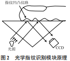
The AS608 optical fingerprint recognition module utilizes the principles of light refraction and reflection [5]. The two basic functions of the fingerprint recognition module are: one is to collect fingerprint image information; the other is to compare the new fingerprint with the existing fingerprint to achieve identity recognition. The fingerprint recognition module contains a light-emitting diode and a charge-coupled device (CCD). The light-emitting diode provides the light source for the module, illuminating the fingerprint on the finger; the CCD is a group of light-sensitive diodes, each light-sensitive device records a pixel. The module has an analog-to-digital converter that can convert the pixel recorded by the light-sensitive device into an analog electronic signal, thus digitizing the image. When a finger is placed on the prism of the fingerprint recognition module, the light-emitting diode provides a light source to illuminate the fingerprint, and the light is emitted from the bottom towards the prism. The refraction angles of the light beams on the uneven fingerprint ridges and the light and dark vary, and the CCD collects images with different brightness, thus completing fingerprint collection [6]. The principle of the optical fingerprint recognition module is shown in Figure 2.
The commonly used interfaces of the module include 8, including the power interface VDD and GND, the module’s UART communication interfaces TXD and RXD, where the module’s TXD is the data transmission interface connected to the main controller’s RXD; the module’s RXD is the data transmission interface connected to the main controller’s TXD. Both pins are 3.0V signal levels, and when connected to a 3.3V main controller, a 1kΩ resistor must be connected in series. The LDO voltage regulator chip enable pin is EN. The module has a reset pin RESET. The module also has 2 communication indication pins: NET network status output pin and asynchronous message notification pin.
2.3 Fingerprint Recognition Module
The fingerprint recognition uses the AS608 optical fingerprint recognition module. AS608 integrates a fingerprint recognition algorithm that can quickly acquire and recognize fingerprints; this module is particularly common in safes, attendance machines, and access control systems. The data transmission and reception between the fingerprint recognition module and the main control are packaged according to a certain command format. The data packet must also be parsed according to the specified command format. The module command mode has 3 types: data packet format, naming packet format, and end packet mode. The command packet and data packet include the packet header, chip address, packet identifier, and packet length; the difference between the data packet and the end packet is the packet identifier. A data packet must follow the command packet or response packet, and the data packet cannot enter the execution process independently.
The AS608 optical fingerprint recognition module utilizes the principles of light refraction and reflection [5]. The two basic functions of the fingerprint recognition module are: one is to collect fingerprint image information; the other is to compare the new fingerprint with the existing fingerprint to achieve identity recognition. The fingerprint recognition module contains a light-emitting diode and a charge-coupled device (CCD). The light-emitting diode provides the light source for the module, illuminating the fingerprint on the finger; the CCD is a group of light-sensitive diodes, each light-sensitive device records a pixel. The module has an analog-to-digital converter that can convert the pixel recorded by the light-sensitive device into an analog electronic signal, thus digitizing the image. When a finger is placed on the prism of the fingerprint recognition module, the light-emitting diode provides a light source to illuminate the fingerprint, and the light is emitted from the bottom towards the prism. The refraction angles of the light beams on the uneven fingerprint ridges and the light and dark vary, and the CCD collects images with different brightness, thus completing fingerprint collection [6]. The principle of the optical fingerprint recognition module is shown in Figure 2.
 The system uses an electromagnetic lock to replace ordinary mechanical locks, achieving automated control. The access control lock module consists of an electromagnetic lock and an opto-isolated relay. The main controller pins cannot directly drive the electromagnetic lock, so an opto-isolated relay needs to be added in front of the electromagnetic lock [7]. When the optical fingerprint recognition module recognizes an existing fingerprint, the main control sends a signal to energize the relay and power the electromagnetic lock, opening the door. The relay has normally closed and normally open contacts; to reduce power consumption, this system uses normally open contacts. When powered, the normally open interface short-circuits with the COM public interface. The IN interface in the module connects with the main control, and the relay can be energized by outputting a high or low level from the main control pin. The trigger mode of the module (high-level trigger or low-level trigger) can be selected via jumpers.
2.5 Voice Broadcast Module
The voice broadcast module in the system implements a user-friendly design. The voice broadcast module is mainly used for broadcasting information on identity recognition, fingerprint enrollment, deletion, and other operations. The voice broadcast module uses a Chinese TTS text-to-speech synthesis module. This module can directly convert Chinese characters, uppercase and lowercase English letters, and numbers into voice output. By outputting content via the serial port, for example, to broadcast “Fingerprint deletion successful,” the code is Serial.print(“Fingerprint deletion successful”). The module communicates via UART, with the module’s TXD and RXD connected to the main controller’s RXD and TXD, respectively. During the use of this module, it is important to add a delay statement after the voice output, allowing sufficient time for the voice module to finish reading the broadcast information.
2.6 Battery Voltage Detection Circuit
To prevent the problem of being unable to open access when power is out, a rechargeable battery is built into the system. The battery voltage is one of the important parameters of the battery, and the system collects the voltage and transmits the data to the platform. The maximum input voltage of the main control’s analog interface is 5V, so the voltage is collected using a resistor divider method [8]. In the battery voltage detection circuit, it is also necessary to consider one issue: the resistance in the circuit cannot be too small, otherwise, it will cause the battery to continuously power the entire circuit, consuming a lot of battery power. To address this issue, an NMOS transistor can be connected in series in the resistor divider circuit; when battery voltage detection is not needed, the main control outputs a low level to turn off the NMOS, reducing battery loss [9].
Fingerprint enrollment, deletion, verification, and access opening information are displayed on the LCD12864 screen [10]. Ordinary LCD12864 displays have too many interfaces, making wiring cumbersome and occupying too many pins of the main controller. Therefore, this system uses an I2C interface display. The I2C interface display requires only four wires to achieve data communication, including the power line. The main control chip of this display is ST7920, which is a COB (Chip On Board) LCD that internally has the GB2312 Chinese character library. To display Chinese, you only need to extract the internal code using the character library extraction software. This display not only facilitates displaying Chinese but can also display BIN format images; you just need to store the pre-made images on the display using the corresponding download tools and then successfully display them through the main control program. The display has 8 pins, and connecting only 5 of them is sufficient for communication. The 5 pins are GND, VDD, SCL, SDA, and BUSY. Among them, GND and VDD are for power; SCL is the I2C clock signal line; SDA is the I2C data signal line; BUSY is the busy signal, with a high level indicating busy and a low level indicating idle. The display’s SCL connects to the main control’s Mega2560 Pro’s D21 (SCL) pin; the display’s SDA connects to the main control’s Mega2560 Pro’s D22 (SDA) pin; BUSY connects to the main control’s D34 pin.
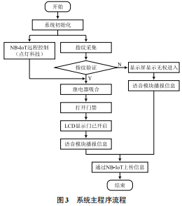
After system initialization, fingerprint enrollment is performed first. When someone places their finger on the fingerprint recognition module’s glass plate, the module begins to collect the current fingerprint and perform comparisons; after comparison, if it is a previously stored fingerprint, the relay will be energized to close, opening the electromagnetic lock and unlocking the access control. After unlocking, the voice broadcast will say “Access has been opened,” and the display will show access opening information. The validated fingerprint ID is transmitted to the IoT platform (Dandeng Technology) via NB-IoT; management personnel can log into the platform or APP to view access opening information. When unauthorized individuals need to enter, management personnel can remotely control the unlocking via the platform or enter a temporary authorization code provided by the management personnel. The main program flow of the system is shown in Figure 3.
The intelligent access control designed in this article achieves identity recognition through the optical fingerprint recognition module. It realizes a user-friendly human-computer interaction interface through the LCD display and voice broadcast module. Remote monitoring and control are achieved through the NB-IoT module. When unauthorized individuals need to enter the computer room, management personnel can perform remote control via the platform or APP. The system includes a rechargeable battery that can solve the problem of management personnel being unable to enter the computer room for inspection due to power outages. Compared with traditional mechanical access control, the system improves security, reliability, and enhances the intelligence level of the campus.
The system uses an electromagnetic lock to replace ordinary mechanical locks, achieving automated control. The access control lock module consists of an electromagnetic lock and an opto-isolated relay. The main controller pins cannot directly drive the electromagnetic lock, so an opto-isolated relay needs to be added in front of the electromagnetic lock [7]. When the optical fingerprint recognition module recognizes an existing fingerprint, the main control sends a signal to energize the relay and power the electromagnetic lock, opening the door. The relay has normally closed and normally open contacts; to reduce power consumption, this system uses normally open contacts. When powered, the normally open interface short-circuits with the COM public interface. The IN interface in the module connects with the main control, and the relay can be energized by outputting a high or low level from the main control pin. The trigger mode of the module (high-level trigger or low-level trigger) can be selected via jumpers.
2.5 Voice Broadcast Module
The voice broadcast module in the system implements a user-friendly design. The voice broadcast module is mainly used for broadcasting information on identity recognition, fingerprint enrollment, deletion, and other operations. The voice broadcast module uses a Chinese TTS text-to-speech synthesis module. This module can directly convert Chinese characters, uppercase and lowercase English letters, and numbers into voice output. By outputting content via the serial port, for example, to broadcast “Fingerprint deletion successful,” the code is Serial.print(“Fingerprint deletion successful”). The module communicates via UART, with the module’s TXD and RXD connected to the main controller’s RXD and TXD, respectively. During the use of this module, it is important to add a delay statement after the voice output, allowing sufficient time for the voice module to finish reading the broadcast information.
2.6 Battery Voltage Detection Circuit
To prevent the problem of being unable to open access when power is out, a rechargeable battery is built into the system. The battery voltage is one of the important parameters of the battery, and the system collects the voltage and transmits the data to the platform. The maximum input voltage of the main control’s analog interface is 5V, so the voltage is collected using a resistor divider method [8]. In the battery voltage detection circuit, it is also necessary to consider one issue: the resistance in the circuit cannot be too small, otherwise, it will cause the battery to continuously power the entire circuit, consuming a lot of battery power. To address this issue, an NMOS transistor can be connected in series in the resistor divider circuit; when battery voltage detection is not needed, the main control outputs a low level to turn off the NMOS, reducing battery loss [9].
Fingerprint enrollment, deletion, verification, and access opening information are displayed on the LCD12864 screen [10]. Ordinary LCD12864 displays have too many interfaces, making wiring cumbersome and occupying too many pins of the main controller. Therefore, this system uses an I2C interface display. The I2C interface display requires only four wires to achieve data communication, including the power line. The main control chip of this display is ST7920, which is a COB (Chip On Board) LCD that internally has the GB2312 Chinese character library. To display Chinese, you only need to extract the internal code using the character library extraction software. This display not only facilitates displaying Chinese but can also display BIN format images; you just need to store the pre-made images on the display using the corresponding download tools and then successfully display them through the main control program. The display has 8 pins, and connecting only 5 of them is sufficient for communication. The 5 pins are GND, VDD, SCL, SDA, and BUSY. Among them, GND and VDD are for power; SCL is the I2C clock signal line; SDA is the I2C data signal line; BUSY is the busy signal, with a high level indicating busy and a low level indicating idle. The display’s SCL connects to the main control’s Mega2560 Pro’s D21 (SCL) pin; the display’s SDA connects to the main control’s Mega2560 Pro’s D22 (SDA) pin; BUSY connects to the main control’s D34 pin.
After system initialization, fingerprint enrollment is performed first. When someone places their finger on the fingerprint recognition module’s glass plate, the module begins to collect the current fingerprint and perform comparisons; after comparison, if it is a previously stored fingerprint, the relay will be energized to close, opening the electromagnetic lock and unlocking the access control. After unlocking, the voice broadcast will say “Access has been opened,” and the display will show access opening information. The validated fingerprint ID is transmitted to the IoT platform (Dandeng Technology) via NB-IoT; management personnel can log into the platform or APP to view access opening information. When unauthorized individuals need to enter, management personnel can remotely control the unlocking via the platform or enter a temporary authorization code provided by the management personnel. The main program flow of the system is shown in Figure 3.
The intelligent access control designed in this article achieves identity recognition through the optical fingerprint recognition module. It realizes a user-friendly human-computer interaction interface through the LCD display and voice broadcast module. Remote monitoring and control are achieved through the NB-IoT module. When unauthorized individuals need to enter the computer room, management personnel can perform remote control via the platform or APP. The system includes a rechargeable battery that can solve the problem of management personnel being unable to enter the computer room for inspection due to power outages. Compared with traditional mechanical access control, the system improves security, reliability, and enhances the intelligence level of the campus.
References
[1] National Market Supervision Administration, National Standardization Administration of China. Smart Campus Overall Framework GB/T 36342-2018 [S]. 2018.
[2] Na Feng. Application of Intelligent Access Control Based on IoT Technology in Communication Rooms [J]. IoT Technology, 2019, 9 (12): 66-67.
[3] Chen Fugang, Wang Zonghui, Wang Hui, et al. Design of Ultrasonic Water Meter Based on NB-IoT Network [J]. Automation and Instrumentation, 2021, 41 (10): 220-226.
[4] Meng Meng. Design and Implementation of IoT Data Collector Based on Arduino [D]. Beijing: Beijing University of Technology, 2016.
[5] Chen Dirong. Design and Development of Smart Campus Dormitory Fingerprint Lock Based on NB-IoT [D]. Hangzhou: Zhejiang Sci-Tech University, 2021.
[6] Hao Haiyan, Gong Jie. Design of Fingerprint Attendance System Based on Microcontroller [J]. Neijiang Science and Technology, 2021, 42 (7): 47-48.
[7] Zhang Tianqi, Wang Jin, Li Yuehua. Design and Implementation of Intelligent Access Control Lock Based on Narrowband IoT [J]. Journal of Nantong University (Natural Science Edition), 2020, 19 (2): 50-55.
[8] Wang Yulong, Cai Zhizhuan, Xu Jingyun, et al. Voltage Inspection Circuit for Series Lithium-Ion Battery Pack [J]. Electronic Design Engineering, 2019, 27 (13): 143-147.
[9] Zhang Ning. Design and Implementation of Intelligent Street Light Control System Based on NB-IoT [D]. Lanzhou: Lanzhou University, 2019.
[10] Li Long, Chen Feifeng, Yue Mei, et al. Design of Access Control System Based on Fingerprint Recognition [J]. Electronic Production, 2021, 28 (3): 34-36.
Author Introduction:
Lai Ruiqiang (1993—), male, from Quanzhou, Fujian, undergraduate, teaching assistant, main research direction is electronic technology application, IoT technology application, mainly engaged in basic computer teaching work.