 Introduction
In low-power applications, it is sometimes necessary to put the MCU into STOP mode to save power. In some chip architectures, to achieve this, the serial port pins are often configured as general I/O pins with external interrupt mode before entering low-power mode. While this can achieve the desired effect, it inevitably leads to the loss of some initial data.
Some series of chips in the STM32 family have integrated low-power UART, known as LPUART, which perfectly combines low power consumption, data communication, and normal wake-up functionality.
We can use the new LPUART to wake the MCU from STOP mode without losing communication data. However, there are certain usage limitations when waking the MCU from STOP mode using LPUART. Below, we will provide a detailed introduction.
Analysis of Waking Up Using LPUART Under Different Clocks
1. Using HSI16 for LPUART
Using HSI16 as the clock for LPUART allows for a higher baud rate. However, there is an issue to note when using LPUART to wake up, which is the problem of the time difference between high baud rates and the wake-up time of LPUART. Taking STM32L431 as an example, according to its datasheet, the wake-up time for LPUART is as follows:
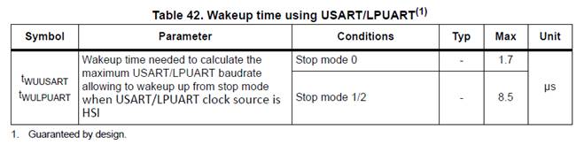
Let’s discuss a practical case from a customer. They reported that the first byte is lost when waking up at a baud rate of 576000. Let’s analyze this situation in detail.
If the application is in STOP MODE 1/2, the maximum wake-up time is 8.5us, which cannot exceed the maximum time tolerance that asynchronous serial communication can handle. After all, asynchronous serial communication does not wait for this wake-up time. Therefore, what we need to do now is to determine the maximum safe communication baud rate for the serial port under these conditions.
First, we need the following two parameters:
tWULPUART (the wake-up time of the MCU from STOP mode), which can be found in the datasheet (as shown in the table above).
The allowable tolerance for LPUART reception (as shown in the table below):
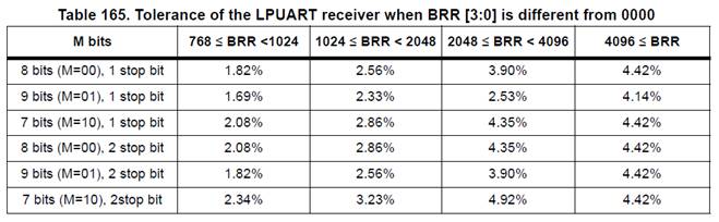
Next, we take 8 bits, 1 STOP bit, BRR ≥4096, STOP 2 mode as an example:
From the table “Table 165: Tolerance of the LPUART receiver when BRR[3:0] is different from 0000”, we find that the reception tolerance of LPUART in this case is 4.42%.
The tolerance formula is: DTRA + DQUANT + DREC + DTCL + DWU < USART
DTRA: Expected transmission tolerance (this includes the deviation of the transmitter’s own oscillator)
DQUANT: Baud rate reception error rate
DREC: Deviation of the receiving crystal
DTCL: Transmission deviation rate (generally, the transmitter uses asymmetric rising and falling edge timing)
DWU: The error rate caused by the deviation of the sampling point after waking from stop mode.
To simplify calculations, we assume DTRA, DQUANT, DREC, and DTCL are 0%, so DWU is 4.42%. To be more accurate, I also need to consider the error of the crystal, using an HSI error of 1%, tWULPUART = 8.5uS (using STOP2 here):
DREC + DWU < LPUART
=>1% + DWU <4.42%
=>DWU<3.42%
Since we are using 8 bits, 1 stop, we have:
M[1:0] = 00:
DWU = tWUUSART/(10 × Tbit)
Tbit min = 8.5us/(10* 3.42%)
Tbit min = 24.8us
Therefore, under these conditions, the maximum allowable baud rate for the asynchronous serial port is 1/24.8us, which must be less than 40.3K baud rate. The baud rate used by our customer is 576000, which is obviously too high, and it is easy to understand why the first byte is lost. When changed to 19200, the problem was resolved.
2. Using LSE for LPUART
With the above analysis, using LPUART with LSE is relatively simple. Since LSE is only 32.768KHz, the maximum baud rate for LPUART can only reach 9600. With the speed reduced, naturally, there are not so many issues.
Conclusion: Occasionally, people ask similar questions. In fact, this issue is described in the relevant reference manuals for STM32 chips. In summary, when encountering problems during development, it is advisable to check the relevant sections of the chip technical manual, as some may be specifically described, while others may be side notes or reminders【Note/Caution】.
================================
Related Links from Previous Topics:
1. Ways and means to obtain ST MCU technical materials and related support
2. Discussion on data loss in USART reception caused by Flash erase operations
3. Cases of abnormal reception when the serial port operates in DMA mode
4. Introduction to periodically triggering ADC using STM32 timers
5. A topic related to STM32 GPIO output rate