
Current measurement accuracy and reliability are crucial for photovoltaic inverter systems, as they determine the control precision of the power stage and further affect energy collection efficiency. For high-voltage photovoltaic inverter systems, the installation of hole-mounted Hall effect current sensors (or magnetic current sensors, for example) has inherent isolation characteristics, and the measurement does not interfere with the measurement circuit, thus providing convenience for wiring and installation.
Closed-loop Hall effect current sensors can provide high precision, fast response, low sensitivity, and low non-linearity error. These sensors require additional magnetic cores, coils, and high-power amplifiers to drive the coils, which makes closed-loop Hall effect current sensors more complex in structure, larger in size, higher in power consumption, and more expensive compared to open-loop Hall effect current sensors. Therefore, considering the trade-off between performance and complexity, open-loop hole-mounted Hall effect current sensors have long been widely used in photovoltaic inverter systems.
However, open-loop hole-mounted Hall effect current sensors typically cannot achieve high precision within their lifespan and temperature range. Additionally, due to the potential for brittle damage to the magnetic core, these sensors are prone to failure during installation and transportation, reducing system reliability. If open-loop Hall effect current sensors could provide sufficient precision, responsiveness, sensitivity, and non-linearity performance like closed-loop current sensors, it would be very beneficial. A better choice is to use package-in-Hall effect current sensors such as the TMCS112x and TMCS113x. The package-in-Hall effect current sensors produced by TI feature high precision and low drift, enabling accurate current measurement regardless of variations in time and temperature. Furthermore, the integrated package design facilitates compact designs without compromising isolation performance and does not increase system complexity or cost. In recent years, there has been a trend in photovoltaic inverter systems to replace traditional hole-mounted sensors with package-in-Hall effect current sensors, which benefits the performance, power efficiency, and reliability of solar systems.
Solar application scenarios using Hall effect current detection
Common solar application scenarios with Hall effect current detection capabilities include string inverters, residential inverters, hybrid inverters, micro-inverters, photovoltaic power optimizers, and smart combiner boxes for central inverters.
1. String Inverters
String inverters are typically three-phase inverters deployed in commercial and utility systems. The power rating is usually greater than 50kW. Figure 1 shows a typical block diagram of a three-phase string inverter, where Hall effect current sensors are used to measure the following currents.
• String current sampling.
• Arc current detection (optional).
• MPPT boost current sampling.
• Three-phase current sampling.
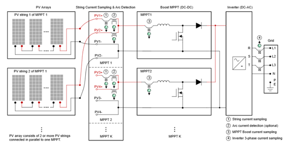
Figure 1 Block diagram of a three-phase string inverter with Hall effect current sensors
1.1 String Current Sampling
In addition to string current display functionality, string current sampling is also used for I-V curve scanning and diagnostics to enable intelligent maintenance work. PV power plants have a large number of PV strings. At the same time, a PV string is composed of multiple PV modules (PV panels). In fact, any PV module or electrical connection may have potential faults or risks that lead to power generation losses. For example, shading, dust, and cracked glass panels may cause current mismatch in the string. Diode short circuits, cable disconnections, potential induced degradation (PID), and hot spots may lead to low open-circuit voltage in the string.
The challenge faced by PV systems is how to accurately and quickly locate and address these faults or risks. The traditional method is offline manual inspection, which is highly inefficient and costly. The currently popular method is online I-V curve scanning and diagnostics to improve the efficiency and accuracy of fault identification in PV systems.
Figure 2 shows examples of normal and abnormal I-V curve scanning and diagnostics. Since anomalies in PV systems can lead to different changes in the I-V characteristic curve, the results of I-V curve monitoring can be used to analyze potential faults or risks during the operation of the PV system. Therefore, the accuracy of string current and voltage sampling is one of the key factors determining the final fault diagnosis accuracy, which indirectly determines power generation efficiency. This is very important for commercial-industrial PV power plants and utility PV power plants, as output is critical for them.
It is also worth noting that maximum power point tracking (MPPT) in string inverters is typically implemented at the PV array level, while I-V curve scanning is implemented at the individual string level.
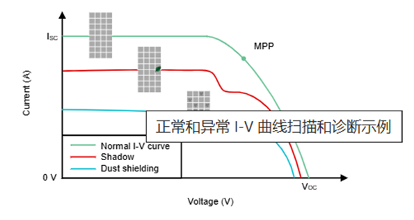
Figure 2 Examples of normal and abnormal I-V curve scanning and diagnostics
1.2 Arc Current Detection (Optional)
Arc fault circuit interrupters (AFCI) are an emerging requirement in solar systems and are gradually becoming mandatory in the laws and regulations of certain countries/regions. According to UL 1699B, AFCI is required for solar equipment to prevent hazards, especially fires occurring during PV panel installations. Arc current detection is needed to collect and analyze the AC noise current present on the DC current between the PV string and the inverter, and then distinguish between arc and non-arc events.
Arc current ranges from tens of mA to several amperes, with a spectrum as low as a few kHz and up to several hundred kHz. Such frequencies require current sensors to have high sensitivity, high bandwidth, and low noise levels. Current transformers (CT) can provide high measurement accuracy and safe isolation between the primary high current side and the secondary low current side. This device has been widely used as an arc current detection sensor. However, CTs have drawbacks, such as power loss and occupying a large PCB size. Package-in-Hall effect current detection designs are also gradually becoming a new trend for arc current detection.
1.3 MPPT Boost Current Sampling
As shown in Figure 1, the MPPT stage is typically implemented using a boost topology. Sampling the voltage and current of the PV array serves as control input signals for MPPT. Average inductor current is typically sampled, and the MPPT control frequency is much lower than the switching frequency. The accuracy of MPPT boost current sampling is as crucial as that of string current sampling, as it determines the accuracy of MPPT, which ultimately affects power generation efficiency.
1.4 Three-Phase Current Sampling
Three-phase current sampling of the inverter includes the AC currents (R phase, S phase, T phase) and the corresponding DC components. A typical block diagram of three-phase current sampling and signal conditioning is shown in Figure 2-3. Phase currents are sampled by DSP ADC for statistical inverter power stage control and power generation information. The AC components of phase currents will be filtered out, retaining only the DC components, which are then amplified and sampled by DSP ADC for DC component suppression control.
For grid-tied inverters, theoretically, only AC current is allowed to be injected into the grid. However, in practice, the output current of the inverter inevitably contains some DC components, which can damage the grid, grid loads, and grid equipment. Therefore, it is unlikely to completely remove the DC components from the inverter, but it is necessary to control them within a specific low range. Standards such as IEEE 1547-2018 define limits for DC components in the AC current on the grid side, such as below 0.5% of the rated output current.
The accuracy of three-phase current sampling is very important for inverter power stage control, power generation statistics, and DC component suppression. Especially for the issue of excessive DC components, using Hall effect current sensors with high precision and low drift can be very beneficial in addressing the problem at the outset.
Another related issue regarding current sensor accuracy is reactive power generation. For active power generation, the reference for the current loop is generated by the voltage loop. The errors of current sensors can be greatly mitigated by the current controller, in which case the accuracy of DC bus voltage detection is very important. However, for reactive power generation, the reference for reactive current is directly generated by the MCU. Therefore, if the current sensor is inaccurate, the output current of the inverter cannot be set to the desired value. Using high-precision TI Hall effect current sensors is also beneficial in solving such issues.
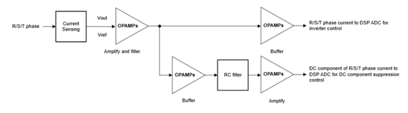
Figure 3 Typical block diagram of three-phase current sampling and signal conditioning
2. Single-Phase Residential Inverters
Residential inverters typically refer to single-phase inverters and three-phase inverters deployed in residential systems. The power rating of single-phase inverters is usually less than 10KW, while that of three-phase inverters is typically between 10KW and 50KW. The system architecture of three-phase residential inverters is very similar to that of string inverters discussed earlier.
The main difference is that the number of independent MPPT inputs for residential inverters is much smaller, and the number of PV strings per MPPT can be 1 or 2, depending on the power rating. For example, a 50kW three-phase residential inverter has 4 MPPT inputs and a total of 5 to 8 PV string inputs. For single-phase inverters, this aspect is much simpler. For example, a 10KW single-phase residential inverter has 3 MPPT inputs and a total of 3 PV string inputs. Figure 4 shows a typical block diagram of a single-phase residential inverter with Hall effect current sensors.
Considering the power rating of the inverter and the target application scenario, residential inverters do not have strict high precision requirements for string current sampling and MPPT boost current sampling compared to string inverters. Since residential systems are usually independent of each other and deployed on a small scale, even if lower current sampling precision leads to some power generation output loss, it is not a major issue. However, for phase current sampling, residential inverters have the same high precision requirements and corresponding reasons as string inverters.
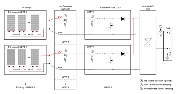
Figure 4 Typical block diagram of a single-phase residential inverter with Hall effect current sensors
3. Three-Phase Hybrid Inverters
Photovoltaic hybrid inverters are devices that combine the advantages of traditional photovoltaic inverters with battery power conversion systems. This process allows users to have more alternatives for producing, storing, and using more environmentally friendly electricity. Hybrid inverters can not only connect multiple PV strings and convert DC to AC but also support direct feeding of DC into battery energy storage systems (BESS). By integrating battery power conversion systems (such as bidirectional DC/DC converters), hybrid inverters eliminate unnecessary DC to AC power conversion through DC bus coupling, thereby reducing losses.
Hybrid inverters are mainly used in residential and small commercial application scenarios. The power rating of single-phase hybrid inverters is usually less than 10KW. The power rating of three-phase hybrid inverters typically ranges from a few KW to several tens of KW. Figure 2-5 shows a typical block diagram of a three-phase hybrid inverter with Hall effect current sensors.
• String current sampling.
• Arc current detection (optional).
• MPPT boost current sampling.
• Inverter three-phase current sampling.
• Bidirectional converter (BDC) current sampling.
• Off-grid emergency power supply (EPS) three-phase current sampling.
• Neutral current sampling for midpoint potential balancing.
Compared to the aforementioned string inverters or residential inverters, hybrid inverters have more Hall effect current sensors due to ESS and off-grid EPS functionalities. Additionally, for markets with frequent power outages (such as Africa), hybrid inverters also support energy acquisition from diesel generators. There is additional off-grid three-phase current sampling at the diesel generator port.
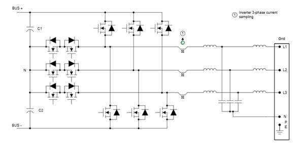
Figure 5 Typical block diagram of a three-phase hybrid inverter with Hall effect current sensors
3.1 BDC Current Sampling
Figure 5 shows an inverter using high-voltage batteries. For high-voltage batteries (typically 150V to 600V), BDC charging and discharging typically use non-isolated two-stage buck/boost topology. Hall effect current sensors can be used for inductor current sampling for control and protection purposes. Additionally, average inductor current can also be used for battery power statistics.
For low-voltage batteries (typically 40V to 60V), isolated topologies such as DAB and CLLLC are typically required. Hall effect current sensors can be used for primary side current, secondary side current, and resonant loop current sampling. For more information, refer to the application brief on isolated bidirectional DC/DC converters in this power conversion system (PCS).
3.2 Off-Grid EPS Three-Phase Current Sampling
EPS (also known as backup power supply) enhances the versatility of hybrid inverters. EPS enables the inverter to operate in both grid-tied mode and off-grid mode (island mode). In grid-tied mode, solar energy first goes to the backup load and normal load. Excess energy will be stored in the battery or fed into the grid. Meanwhile, under conditions where the energy from PV and the battery is less than the power of the backup load, the battery or the grid, or both can supply power to the backup load. The maximum output power capability of the backup load (for example, maximum output current) may exceed the rated AC output power of the inverter. For example, a commonly available 25KW three-phase hybrid inverter supports a maximum AC output current of 37.9A, while in grid-tied mode, it supports a maximum output power of 43KW (63A maximum output current) for backup loads. In off-grid mode, hybrid inverters can obtain energy from solar or batteries during grid interruptions or emergencies, ensuring uninterrupted power supply.
Unlike three-phase current sampling of inverters, theoretically, EPS three-phase current sampling is not used for power stage control and does not need to consider DC component suppression, as for backup loads, even if it exceeds the range, it will not damage the grid, grid loads, and grid equipment. However, this method is used for backup load power consumption statistics, and using Hall effect current sensors with high precision and low drift can improve measurement accuracy and reliability.
3.3 Neutral Current Sampling for Midpoint Potential Balancing
Another important Hall effect current sensor in hybrid inverters is used for neutral current sampling for midpoint potential balancing. In systems designed specifically for three phases, the loads on each phase need to be kept constant. However, in some three-phase residential or commercial application scenarios (such as in Germany and Austria), both three-phase and single-phase loads may be used simultaneously, which can lead to power consumption imbalances between the three phases. This means that one or two phases may have higher power demands than the others. This can lead to neutral line voltage imbalances, causing issues with the grid and grid equipment. Supplying power to single-phase loads in the system means that the output power of each phase depends on the corresponding load consumption, which cannot be the same, and hybrid inverters typically have unbalanced output capabilities. PV inverter suppliers often have some feature specifications, such as supporting 100% unbalanced output in backup mode and grid mode (even up to 110%) in their data sheets.
If the three-phase load is balanced, there should be no current in the neutral line, and the midpoint potential is balanced, for example, reaching half of the bus voltage. Conversely, if the load is unbalanced, the neutral line pull current or sink current will cause a change in midpoint potential. This situation requires compensation for midpoint potential imbalance.
Figure 6 shows the traditional way of using two phase-shifting capacitors. The neutral point is the midpoint of two large electrolytic capacitors C1 and C2 with equivalent capacitance. The neutral line current continues to charge one phase-shifting capacitor while discharging the other capacitor for a specific period to maintain midpoint potential balance. Although there are some small capacitance or voltage mismatches between the two phase-shifting capacitors in practice, this design is easy to implement and is still widely used in string inverters and residential inverters, where the three-phase output to the grid must be balanced. However, for significantly unbalanced outputs, the DC component in the neutral line current can lead to severe voltage mismatches, which can cause inverter fault shutdown protection.
Figure 6 Design of two phase-shifting capacitors for midpoint potential balancing in three-phase inverters
Unlike string or residential inverters, hybrid inverters have a fourth bridge arm (also known as a balancing bridge, thus the inverter is referred to as a three-phase four-bridge-arm inverter), which can actively control the midpoint voltage, allowing the inverter to support unbalanced output, as shown in Figure 2-7. The control of the fourth switch bridge arm is decoupled from the three-phase inverter. Balancing bridge control involves neutral current sampling, where Hall effect current sensors can be used.
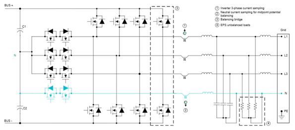
Figure 7 Testing with a 12V load system
4. Split-Phase Hybrid Inverters
Split-phase hybrid inverters are specifically designed to split single-phase power output into two independent phases. This is typically applicable in grid-supporting split-phase situations, such as in the North American (115V/230V) and Japanese (100V/200V) markets. Split-phase inverters have the same unbalanced load output requirements as three-phase hybrid inverters. Figure 8 shows a typical block diagram of a split-phase hybrid inverter with Hall effect current sensors.
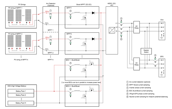
Figure 8 Typical block diagram of a split-phase hybrid inverter with Hall effect current sensors
Figure 9 shows a HERIC inverter with a fourth bridge arm (also known as a balancing bridge), which can actively control the midpoint voltage, allowing the inverter to support split-phase (unbalanced load) output.
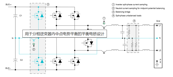
Figure 9 Balancing bridge design for midpoint potential balancing in split-phase inverters
5. Micro-Inverters
Micro-inverters are terminal devices primarily used in residential applications, with rated power ranging from a few hundred watts to several kilowatts. Micro-inverters can be flexibly applied to small rooftops and balconies, integrating BESS to generate and store electricity for household appliances, which helps save electricity costs more efficiently.
Package-in-Hall effect current sensors can be used in micro-inverter applications to significantly reduce PCB size and improve system reliability. Figure 10 shows a typical block diagram of a micro-inverter with Hall effect current sensors, for example,
• AC current sampling.
• Resonant loop current sampling.
AC current sampling primarily detects the 50Hz current injected into the grid, and this current information can also be used to protect the power devices of the DC/AC converter. The AC current sampling of micro-inverters has the same high precision and low drift requirements as mentioned in previous sections.
Resonant loop current sampling can achieve precise turn-on or turn-off of synchronous rectifier transistors and overcurrent protection by determining this current. Therefore, the timing of this current information is very important for improving efficiency, requiring Hall sensors with high bandwidth and low propagation delay.
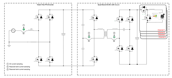
Figure 10 Typical block diagram of a micro-inverter with Hall effect current sensors
6. Photovoltaic Power Optimizers
Power optimizers are terminal devices typically used in conjunction with string inverters. Power optimizers provide module-level monitoring capabilities, rapid shutdown functions, and module-level MPPT functions, enhancing the safety of PV systems and helping to generate greater power for the entire PV string, especially when these strings are in partial shading and other abnormal conditions.
Power optimizers commonly use buck and four-switch buck/boost topologies. Buck topologies typically use low-side current sampling with shunt resistors and amplifiers. Four-switch buck/boost converters typically use high-side current sampling. The input of the optimizer is connected to one PV panel or two series-connected PV panels, with a common mode voltage of up to 150V, where 2 PV panels are in series. Package-in-Hall effect current sensors are ideal for four-switch buck/boost optimizers. As shown in Figure 11, inductor current is sampled for current loop control and protection purposes.
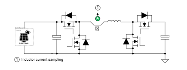
Figure 11 Testing with a 12V load system
7. Smart Combiner Boxes for Central Inverters
Smart combiner boxes (also known as PV combiner boxes, abbreviated as PVS) are used in central inverters for medium to large-scale PV grid-connected power generation systems. To reduce the connection lines between PV strings and inverters, simplify maintenance, and improve reliability, PVS are added between PV strings and inverters. Depending on the size of the central inverter, smart combiner boxes typically support 16/18/20/24/32 channels and sample the current of all PV strings in the box. Figure 12 shows the application scenario of smart combiner boxes using Hall effect current sensors. Similar to the string current sampling described in the string inverter section, the current monitoring function of smart combiner boxes also requires high precision to achieve high fault diagnosis accuracy and power generation efficiency.
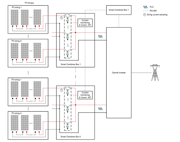
Figure 12 Application scenario of smart combiner boxes using Hall effect current sensors
8. Overview of Photovoltaic Inverter Systems and Package-In-Hall Effect Current Sensors
Table 1 summarizes key information about photovoltaic inverter systems and helps analyze the usage of package-in-Hall effect current sensors, as shown in Table 2.
Table 1 Summary of Photovoltaic Inverter Systems
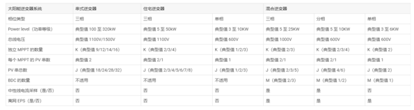
Table 2 Usage Statistics of Package-In-Hall Effect Current Sensors
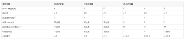
Note:
• For inverter phase current sampling, whether package-in-Hall effect current sensors can be used depends on the power rating (current rating) of the inverter. Package-in-Hall effect current sensors may experience temperature issues in high-power inverters.
• The data in this table is based on buck/boost BDC of inverters using high-voltage batteries. Isolated topologies (such as DAB and CLLLC) with low-voltage batteries, which have more current sensors, are not shown in this table.
• Diesel generators and arc detection are optional features, and the corresponding number of current sensors is not included in the total count. There is additional off-grid phase current sampling at the diesel generator port. The number of arc current sensors equals the total number of PV strings.
Table 3 Examples of Photovoltaic Inverter Systems
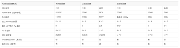
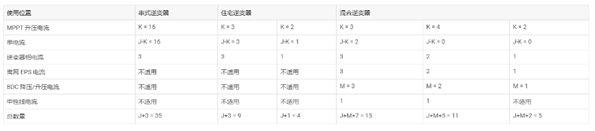
Table 4 Example Usage Statistics of Package-In-Hall Effect Current Sensors
Conclusion
With ongoing investments and developments in solar energy and ESS, more accurate and reliable current detection technologies can make the grid safer and more efficient when collecting energy. Texas Instruments (TI) package-in-Hall effect technology (such as TMCS112x and TMCS113x) not only provides high precision and low drift, enabling accurate current measurement across the entire lifecycle and temperature range, but is also easy to use and cost-effective, making it widely used to replace traditional hole-mounted Hall effect current sensors. This application manual outlines common solar application scenarios where package-in-Hall effect current sensors can be used.