1 Introduction
CAN stands for Controller Area Network, which is a serial communication network capable of achieving distributed real-time control.
Advantages:
The transmission speed can reach up to 1 Mbps, with a maximum communication distance of 10 km, a lossless arbitration mechanism, and a multi-master structure. In recent years, the price of CAN controllers has been decreasing.
Ø Low Cost: ECUs communicate through a single CAN interface, resulting in low wiring costs.
Ø High Integration: The CAN bus system allows centralized error diagnosis and configuration across all ECUs.
Ø Reliability: The system is highly robust against subsystem failures and electromagnetic interference, making it an ideal choice for automotive control systems.
Ø High Efficiency: Messages can be prioritized by ID, ensuring that the highest priority ID is not interrupted.
Ø Flexibility: Each ECU contains a transceiver chip for the CAN bus, allowing for the easy addition of CAN bus nodes.
2 CAN Bus Network
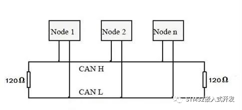
The CAN bus network primarily relies on CAN_H and CAN_L, with each node achieving serial differential signal transmission through these two lines. To avoid signal reflection and interference, a 120-ohm termination resistor must be connected between CAN_H and CAN_L. The reason for 120Ω is that the characteristic impedance of the cable is 120Ω, simulating an infinitely long transmission line.
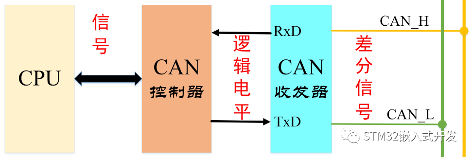
3 CAN Transceiver
The role of the CAN transceiver is to convert between logic levels and signal levels.
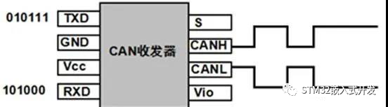
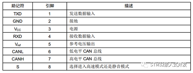
This means that the logic level output from the CAN controller chip is sent to the CAN transceiver, which then converts the logic level into a differential signal output to the CAN bus. Nodes on the CAN bus can determine whether they need the data on the bus. The specific pin definitions are as follows:
4 CAN Signal Representation
The CAN bus uses non-return-to-zero bit stuffing technology, meaning that there are two different signal states on the CAN bus: dominant logic 0 and recessive logic 1. After each signal transmission, there is no need to return to the logic 0 (dominant) level.
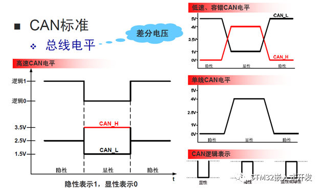
Explanation of dominant and recessive levels:
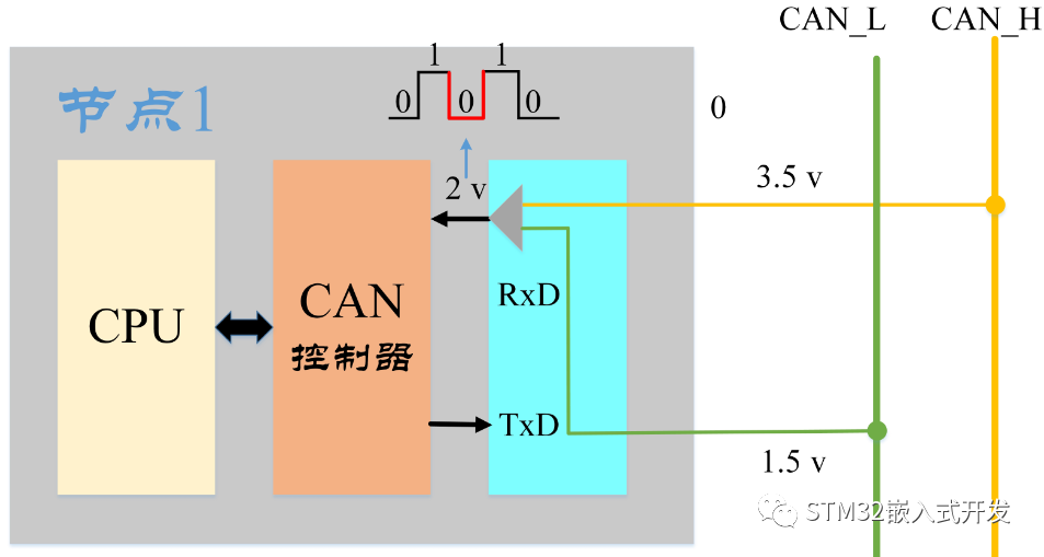
The CAN data bus consists of two lines: one is the yellow CAN_High, and the other is the green CAN_Low. When no data is being sent, both lines are at the same level of 2.5V, referred to as the static level, which is the recessive level. When a signal is sent, the level of CAN_High rises by 1V to 3.5V, while the level of CAN_Low drops by 1V to 1.5V.
According to the definitions:
-
When CAN_H – CAN_L < 0.5V, it is recessive, and the logical signal is represented as “logic 1” – high level.
-
When CAN_H – CAN_L > 0.9V, it is dominant, and the logical signal is represented as “logic 0” – low level.
5 CAN Signal Transmission
Sending Process: The CAN controller converts the signals from the CPU into logic levels (i.e., logic 0 – dominant level or logic 1 – recessive level). The CAN transmitter receives the logic level and converts it into a differential level output to the CAN bus.
Receiving Process: The CAN receiver converts the differential levels received from the CAN_H and CAN_L lines into logic levels output to the CAN controller, which then converts the logic level into the corresponding signal sent to the CPU.
6 CAN Data Transmission
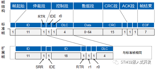
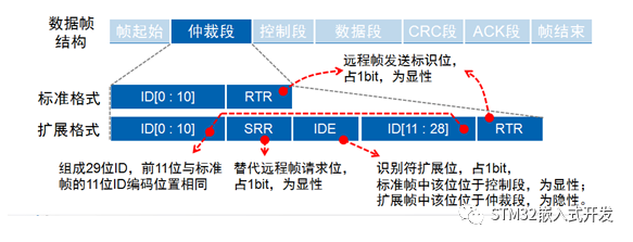
The CAN bus transmits CAN frames, which are divided into five types: data frames, remote frames, error frames, overload frames, and frame intervals.
Data frames are classified into standard frames (2.0A) and extended frames (2.0B) based on the length of the arbitration segment.
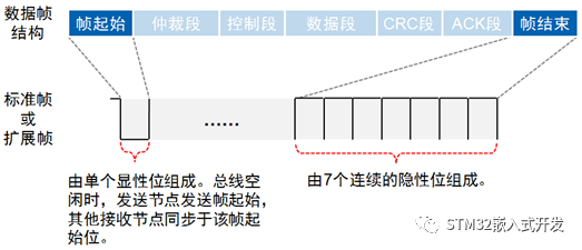
Frame Start
Composed of a dominant bit (low level), the sending node transmits the frame start, and other nodes synchronize to the frame start;
Frame End
Composed of 7 recessive bits (high level).
Arbitration Segment
As long as the bus is idle, any node on the bus can send a message. If two or more nodes start transmitting messages, there is a possibility of bus access conflict. However, CAN uses a bitwise arbitration method based on identifiers to resolve this issue.
The CAN bus controller monitors the bus level while sending data. If the levels differ, it stops sending and takes other actions. If the bit is in the arbitration segment, it exits the bus competition; if in other segments, it generates an error event.
Assuming nodes A, B, and C all send frames of the same format and type, such as standard format data frames, their competition for the bus proceeds as follows:
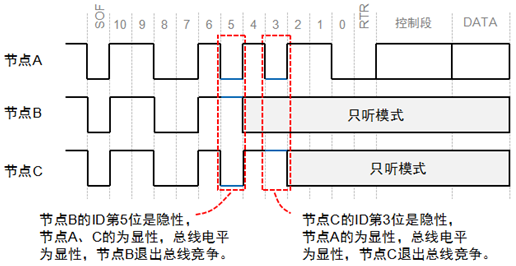
The smaller the frame ID, the higher the priority. Since the RTR bit of the data frame is a dominant level and the remote frame is a recessive level, under the same frame format and ID, data frames take precedence over remote frames; since the IDE bit of the standard frame is a dominant level and that of the extended frame is a recessive level, for the first 11 bits of the ID, the standard frame has a higher priority than the extended frame.
Data Segment
A data frame transmits a data amount of 0 to 8 bytes. This short frame structure allows for high real-time performance of the CAN bus, making it very suitable for automotive and industrial control applications as shown in Figure 27.
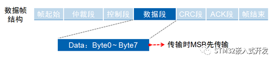
With a small data amount, short sending and receiving times, high real-time performance, low probability of interference, and strong anti-interference capability.