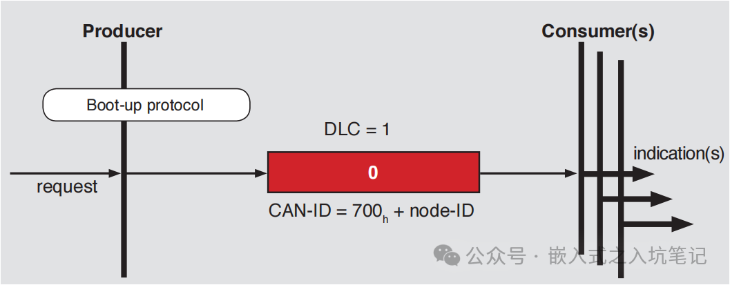
Follow + Star “Embedded Development Notes”, so you won’t miss out on exciting content! Previously, we introduced the basic content of the CANopen protocol. Before learning CANopen, it is essential to understand some basic elements and key points of this protocol.This article mainly discusses nine very important messages in CANopen:1) Boot-up Node Online Message2) Heartbeat Message3) NMT Message4) Node Protection Message5) SDO Message6) PDO Message7) Sync Message8) Timestamp Protocol Message9) Emergency Message ProtocolLink to the article introducing the basic content of CANopen:Still don’t understand CANopen? This article quickly helps you understand what CANopen is.01 Boot-up Node Online MessageIn the CANopen protocol, when a slave node comes online, it must send a node online message to inform the master that it has joined the network.The COB-ID of the node online message is:700h + Node-id, with a data length of 1 and content of 0.As shown in the figure below:
 Using a CAN analyzer to capture the Boot-up online message from slave node number 2 is as follows:
 02 Heartbeat MessageThe purpose of the heartbeat message is to monitor whether the node is online and to confirm the current status of the node. The CANopen protocol requires that all powered-on slave nodes periodically send heartbeat messages, allowing the master to confirm whether the slave has failed or gone offline.The format of the heartbeat message is:700h + Node-id, with a data length of 1 and content representing the node status.
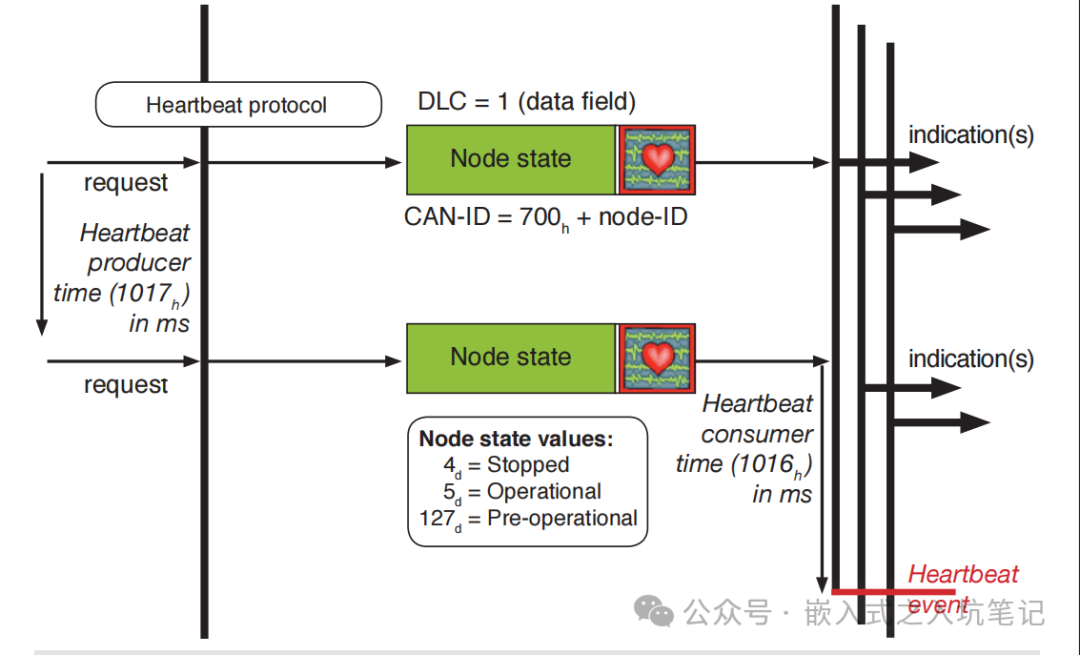 The node status content is as follows:
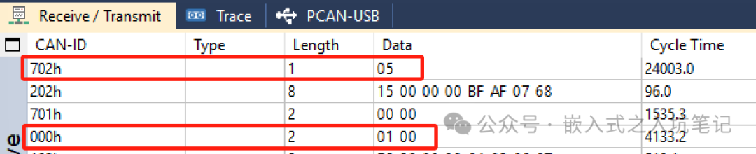
04h - Stopped State 05h - Operational State 7Fh - Pre-Operational StateUsing a CAN analyzer to capture the message from node number 2, which is in pre-operational state after being powered on but not connected to the master, is as follows: The heartbeat message must be generated at intervals, and the time interval can be modified, but it can only be changed by the master sending a message.To modify the time interval for the node to generate heartbeat messages: write data to the object dictionary index=0x1017, subIndex=0x00; the unit is ms; to stop the heartbeat, just write 0.
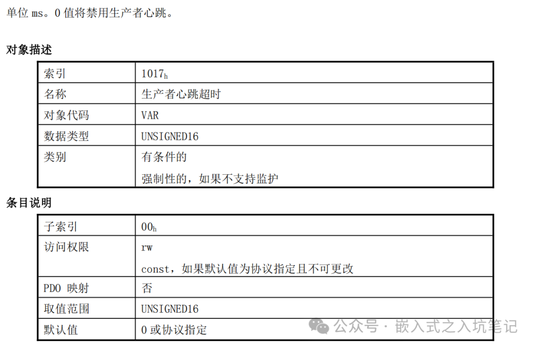 For example: If you want node 2 to generate a heartbeat every 100ms, the SDO message to be sent would be: 602 2B 17 10 00 64 00 00 0003 NMT MessageNMT, or Network Management, is the message used in the CANopen protocol to manage nodes in the network.In CANopen, NMT exists only in the master, which can configure all network nodes, including itself.NMT is very important; after the slave node comes online and sends the Boot-up message, it enters the pre-operational state and requires the NMT master to send a message to control the slave node to enter a certain state. As follows:
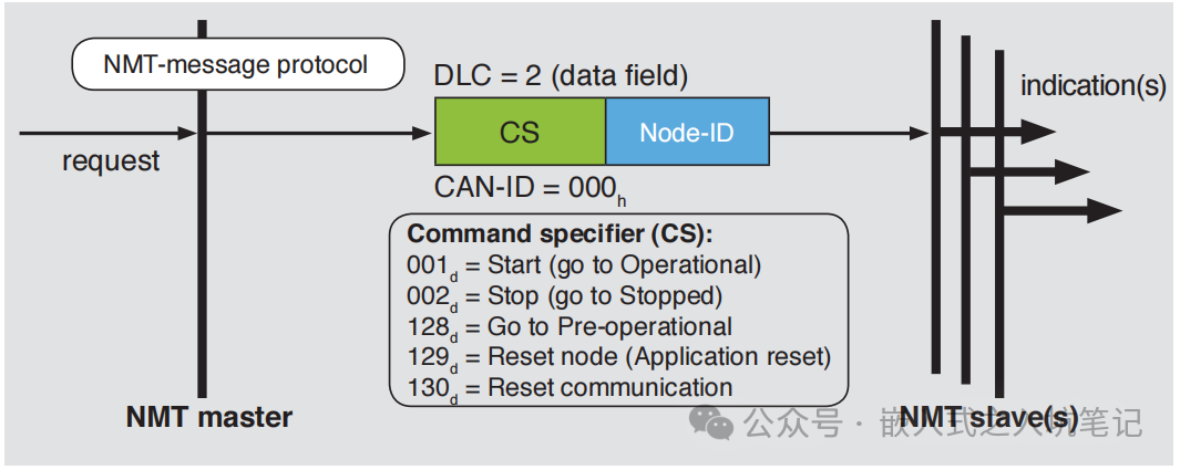 The message format is as follows:
 Where CS is the command word, and Node-ID is the node number.The CS command words are as follows:
01h - Put node into operational mode (running state) 02h - Put node into stopped mode (stopped state) 80h - Put node into pre-operational mode 81h - Reset node (restore to initial state) 82h - Reset node communication (reinitialize the node's CAN and CANopen communication)Note: If you want all nodes on the network to enter a certain state, the node id=00.Application example: The message to put node 2 into operational mode is: 000 01 02; the message to put all nodes into pre-operational state is: 000 80 00.For example, I have a slave that, after powering on, has not connected to the master and is in pre-operational state, the message is as follows: After connecting to the master, the slave node enters operational state (05) as follows:
 04 Node Protection MessageThe node protection message is used by the NMT master node to check the current status of the slave node, with the master actively querying the slave node, and the slave node replying with its current status.
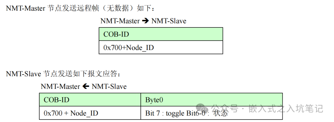 The data part includes a trigger bit (bit7), which must alternate between “0” and “1” in each node protection response. The trigger bit is set to “0” during the first node protection request.Bits 0 to 6 (bits 0-6) represent the node status, which can be as follows:
00h - Initialization State 01h - Not Connected State 02h - Connected State 03h - Pre-Operational State 04h - Stopped State 05h - Operational State 7Fh - Pre-Operational State05 SDO MessageSDO stands for Service Data Object, and the message can be used to read or write data from the slave node’s object dictionary.Generally, the requesting node is the client node, while the node being read or written to is the server node.The data format is as follows: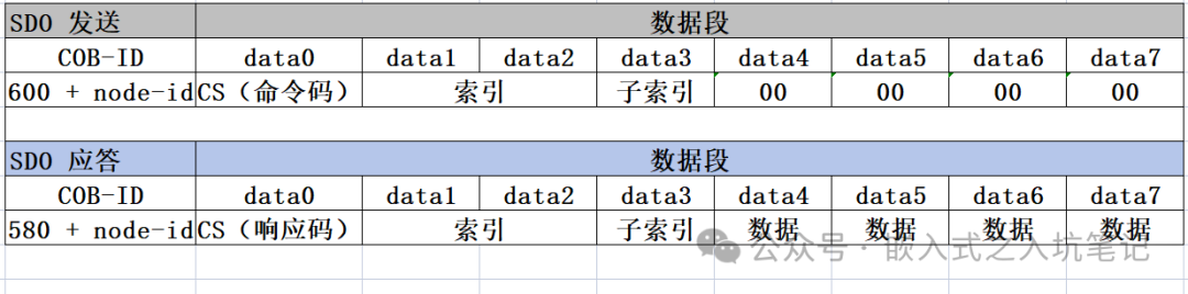 Common command codes and response codes are as follows:
0x21, /*!Segmented Write Request*/ 0x22, /*!Write Request, Length Not Specified*/ 0x23, /*!Write Request, 4-Byte Data*/ 0x27, /*!Write Request, 3-Byte Data*/ 0x2B, /*!Write Request, 2-Byte Data*/ 0x2F, /*!Write Request, 1-Byte Data*/ 0x60, /*!Response to Write Request*/ 0x40, /*!Read Request*/ 0x41, /*!Segmented Data Read Response*/ 0x42, /*!Read Response, Length Not Specified*/ 0x43, /*!Read Response, 4-Byte Data*/ 0x47, /*!Read Response, 3-Byte Data*/ 0x4B, /*!Read Response, 2-Byte Data*/ 0x4F, /*!Read Response, 1-Byte Data*/ 0x60, /*!Segmented Data Read Request*/ 0x70, /*!Segmented Data Read Request*/ 0xA0, /*!Initialize Block Upload*/ 0xA4, /*!Initialize Block Upload, CRC Information*/ 0xC0, /*!Start Block Download*/ 0xC2, /*!Start Block Download, Size Information*/ 0xC4, /*!Start Block Download, CRC Information*/ 0xC6, /*!Start Block Download, CRC and Size*/ 0x80 /*!Abort Transmission*/For example, to write one byte:
Write 1 byte of data: 0xFD to the object dictionary of node 2, index = 0x1500, subindex = 0x02: Send: 602 2F 00 15 02 FD 00 00 00 Response: 582 60 00 15 02 00 00 00 00Another example, to write two bytes:
Write 4 bytes of data: 0x60120208 to the object dictionary of node 2, index = 0x1605, subindex = 0x01: Send: 602 23 05 16 01 08 02 12 60 Response: 582 60 05 16 01 00 00 00 0006 PDO MessagePDO stands for Process Data Object, and the message is transmitted unidirectionally without requiring a response.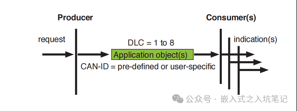 PDO messages can be complex; in the CANopen protocol stack, both sending and receiving PDO messages require setting corresponding communication parameters and mapping parameters, which can be confusing.The usage of PDO messages is as follows:(1) Define the ID range for TPDO and RPDOThe ID is predefined as follows:
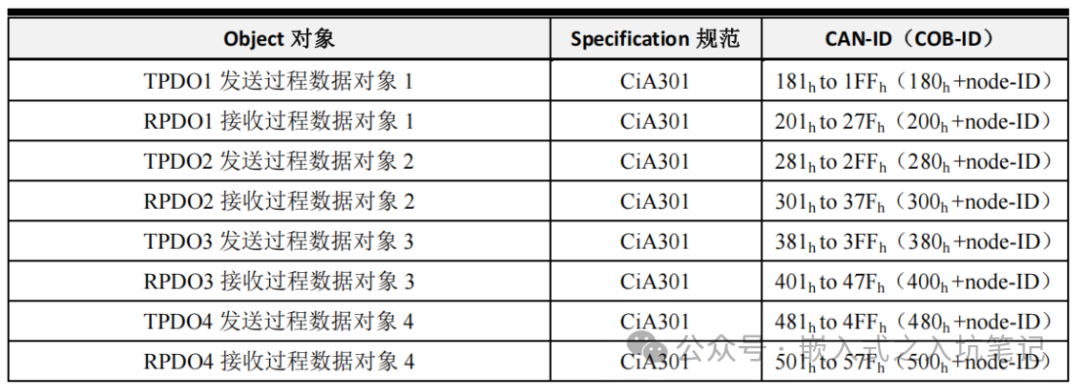 (2) Configure PDO communication parametersThis step mainly involves configuring some important parameters during the PDO communication process, such as associated ID, sending type, event timing trigger time, etc. As follows:
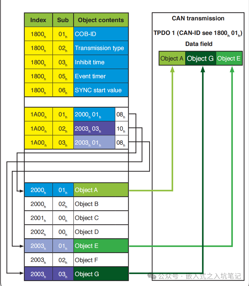
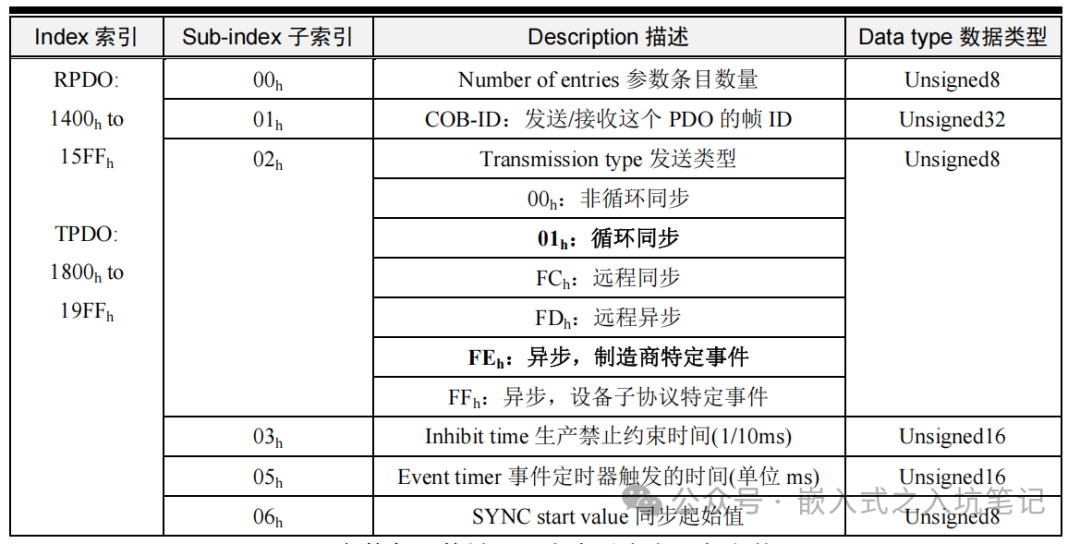 (3) Configure PDO mapping parametersThe mapping parameters are mainly used to map the object dictionary to the corresponding PDO, i.e., to associate communication parameters, application data, and specific CAN message data. As follows:
 07 Sync MessageThe sync message is used to achieve synchronized transmission across the entire network, with each node using this sync message as the trigger parameter for PDO. This message has a higher priority and the shortest transmission time.This message defaults to using ID = 80h as the sync message ID, with no data, and is only used in PDO. As shown in the diagram below:
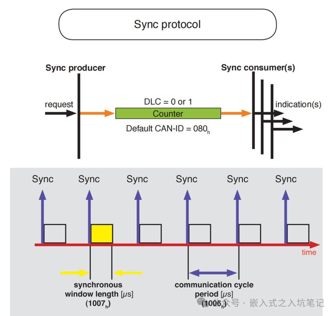 Using the sync message requires configuration, specifically configuring the object dictionary indices 0x1005 and 0x1006. As follows:(1) Object index 1005h – COB-ID of the sync message:
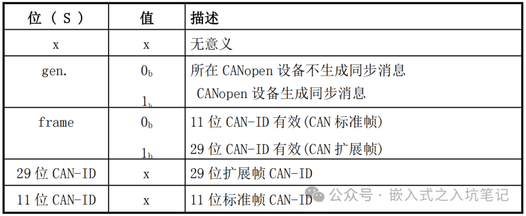 (2) Object index 1006h – Time interval for the sync message
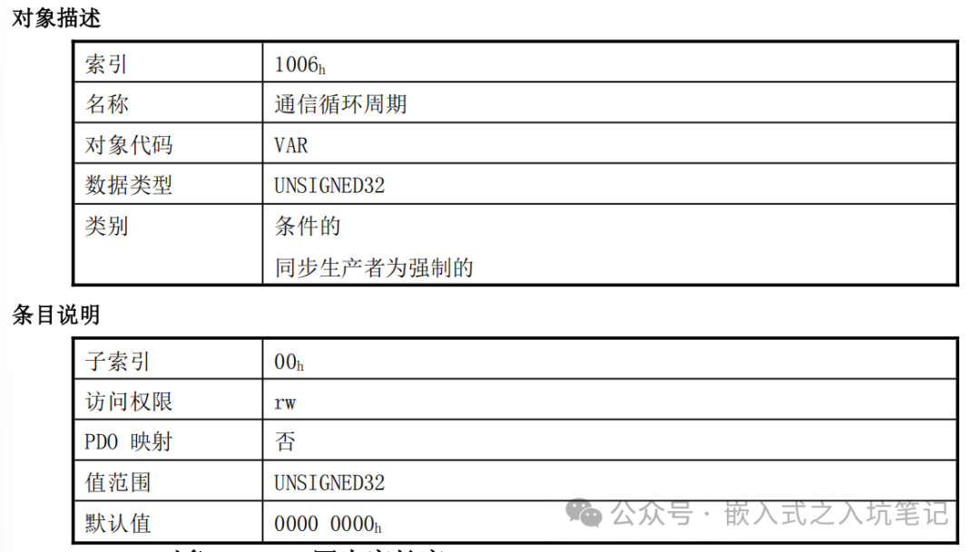 The unit is us; if set to 0000 0000h, SYNC is disabled. If set to a non-0000 0000h value and the overflow value of the sync counter is greater than 0, the first sync message will be sent when the counter value resets to 1.For example: If you want to set the sync message time interval to 1s, write 0xF4240 to index = 0x1006, subindex = 0x00. Write 0x40000080 to index = 0x1005, subindex = 0x00. As follows:
Configure node 2 to send a sync message every 1s: 602 23 06 10 00 40 42 0F 00 // Set sync time 602 23 05 10 00 80 00 00 40 // Start sending sync messages08 Timestamp Protocol MessageThis message is mainly used for network time synchronization, where the NMT master sends its clock to provide a common time reference for all nodes in the network.The timestamp protocol message is sent in a broadcast manner and does not require a node response.ID = 100h, data length = 6, data is the time difference from January 1, 1984, 0:00. As follows: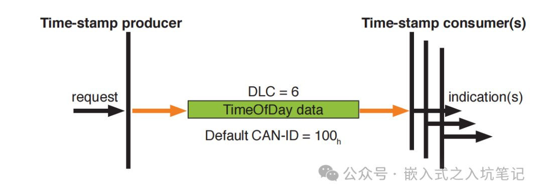 The timestamp object COB-ID needs to be configured at index 1012h, subindex 00h, as follows: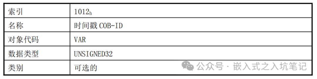
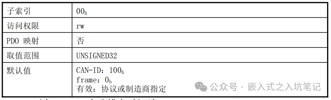 The COB_ID object structure is as follows:
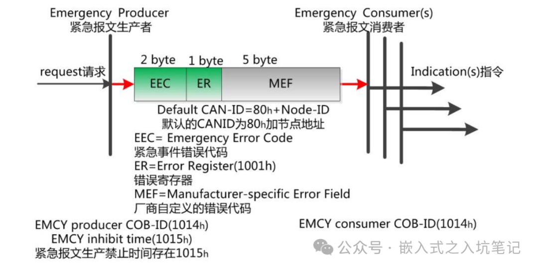
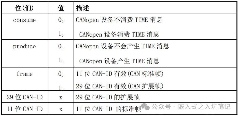 09 Emergency Message ProtocolThe emergency message protocol is mainly triggered when an internal error occurs in the device, sending the internal error code to notify the NMT master.The emergency message is a diagnostic message that usually does not affect CANopen communication. Its ID is stored in the object index 1014h, defaulting to 080h + Node-ID, and the data contains 8 bytes. As follows:
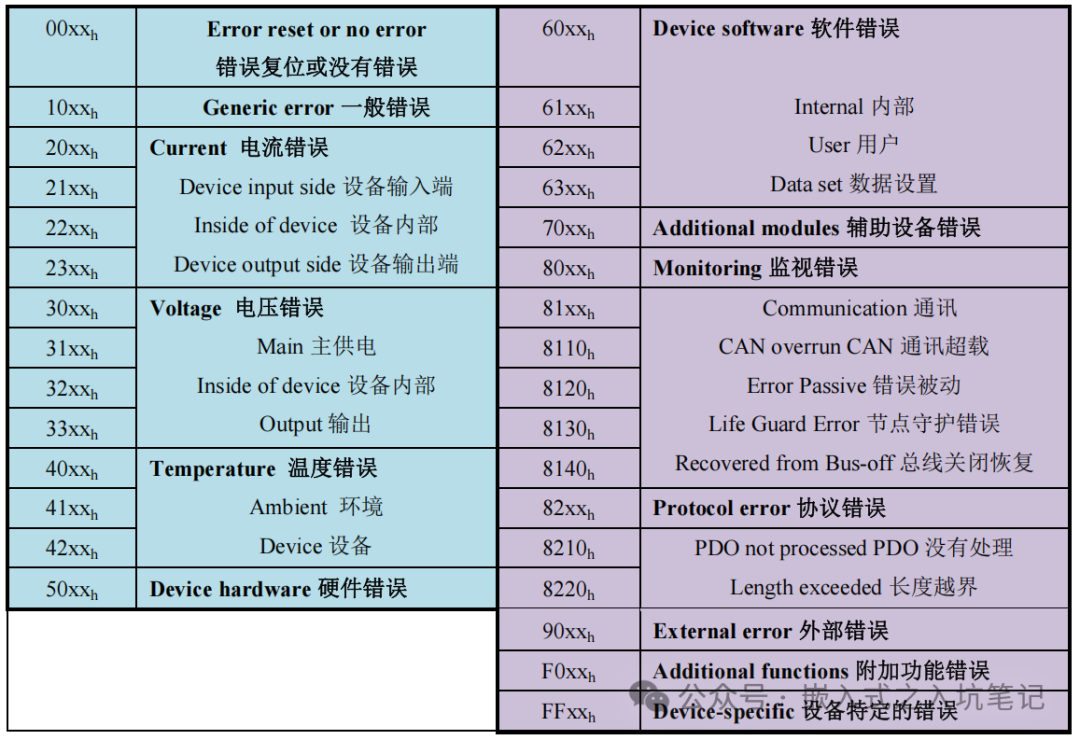
 The emergency message error codes are as follows:
 Some content of this article is referenced from:1) “Easy Introduction to CANopen” by Guangzhou Zhiyuan Electronics2) “CANopen Memorandum by German Engineers” by Guangzhou Zhiyuan Electronics3) “Introduction to CANopen Protocol” by Beijing Bokong Automation
 If you find this article helpful, please follow us!
Please give us a recommendation!