AuthorForum Account: wshuo
1. Introduction
My family lives in a rural area in Northeast China, where winters are very cold. We bought a boiler that requires a circulation pump. Simply put, when the boiler water is heated, the circulation pump automatically turns on, delivering hot water to the heating system. As hot water is drawn away, cold water enters the boiler, causing the temperature to drop, which turns off the circulation pump, waiting for the next heating cycle. Since the houses that need heating are quite far from the boiler, a circulation pump is necessary. If the distance were shorter, the natural convection of hot water rising and cold water returning would complete the cycle automatically. Currently, there are devices on the market that automatically control the circulation pump based on temperature:
The principle involves a thermistor probe (with a magnet that can attach to the boiler wall) controlled by a relay. When the temperature reaches a set value, the relay activates, starting the circulation pump. After circulation, the boiler wall temperature drops, the relay turns off, and the circulation pump stops.
Circulation Pump:
Due to the high power of our circulation pump, the small relay burned out after a few starts, so an AC contactor was added in between (installed by my father).
While these market devices can generally solve the water circulation problem, they have some unresolved details. For example, when the return pipe’s water temperature also reaches the set temperature, the circulation pump remains on, requiring manual adjustment of the temperature knob (to a higher setting) to stop the pump (high-power circulation pumps consume a lot of electricity). Additionally, when the coal in the boiler is nearly burned out (a local term for it), the boiler temperature does not reach the set value, necessitating a reduction in the knob setting to start the circulation pump and utilize the residual heat from the coal.
Due to these shortcomings, someone needs to adjust the knob every few hours. This task is currently performed by my father, so I wanted to create an automated solution to reduce his workload.
2. Project Structure
My initial idea was to allow remote temperature adjustment via a smartphone, so at least manual knob adjustments would not be necessary. I could adjust the temperature from bed at night using my phone. The structure designed based on this initial idea is as follows:
3. Hardware Setup
ESP01 module + relay module, 220V to 5V module + power strip = networked socket
ESP8266 + temperature sensor + digital tube = real-time temperature detection and display network module
My control system is all written in the ESP8266.
Temperature sensor probe construction: To drive the DS18B20 sensor, a 4.7k ohm resistor (pull-up resistor) must be added between the data line (DQ) and the VDD pin. This is essential. I wrapped it in a metal button, placed two small neodymium magnets inside, and filled it with glue to create a temperature sensor probe that can attach to the boiler wall:

I made a mistake at this step by placing both the DS18B20 sensor and the pull-up resistor inside the probe. When measuring temperature, I found that the sensor failed to read the temperature after it increased because the rising temperature caused the resistance value to increase. I later moved the resistor to the end, which solved the problem.
Encapsulated probe:
ESP8266 + digital tube module:
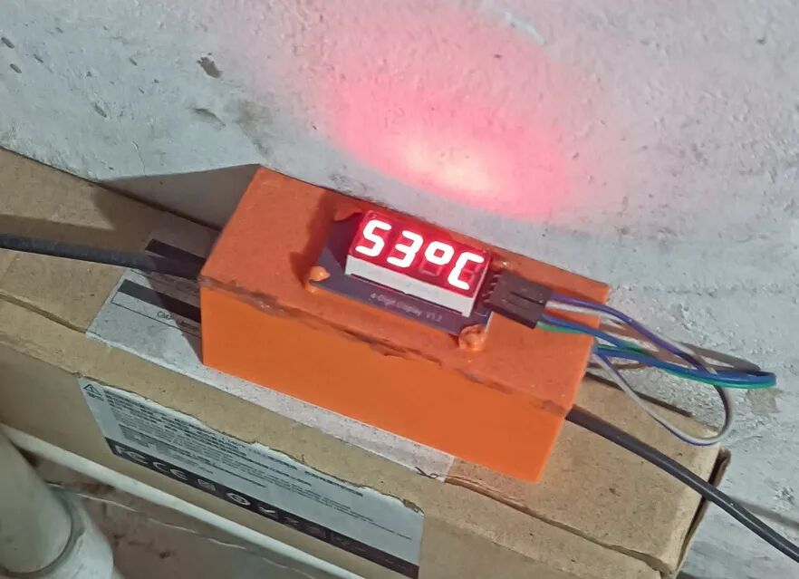
The casing was printed using a 3D printer, housing the ESP8266 module.
4. Software Development
Firmware
I flashed the MicroPython firmware onto both the ESP8266 and ESP01.
Communication
Initially, I considered using sockets for communication, implementing a simple HTTP protocol, but controlling it via a smartphone was cumbersome due to the lack of good software. I also needed to create a web interface, and sockets would block the thread.
Later, I discovered the MQTT protocol, which is a hardware network communication protocol designed for the Internet of Things, capable of handling high-latency network environments. To briefly introduce the MQTT protocol, it requires a server (also known as a broker, which runs on a computer; I run it on a Raspberry Pi), and all your IoT hardware devices (like the ESP8266) act as clients. The IoT hardware devices (clients) do not communicate directly with each other; they communicate directly with the server. If hardware A and hardware B need to communicate, they must first connect to the server. Then, A publishes a topic named “topic”; if hardware B wants to receive A’s information, it must subscribe to that topic. This achieves communication from A to B, and the reverse communication follows the same principle, where B publishes a topic and A subscribes. Another advantage of this protocol is that multiple clients can subscribe to a single topic, enabling multi-end communication. In MQTT communication, each client is unaware of the existence of other clients; they communicate directly with the server.
However, there is a significant issue with MQTT communication in MicroPython firmware (I am unsure if the default firmware from Espressif has this issue): the LmacRxBlk:1 error. For example, if you subscribe to a topic at the beginning and then use a non-blocking method check_msg() to handle the subscribed topic messages via a callback function, if the number of times the subscribed topic publishes exceeds the number of times you call check_msg(), an error LmacRxBlk:1 will occur at the MicroPython firmware level, causing communication to break. In simple terms, if you subscribe to a topic and enter the event loop without processing the subscribed topic messages in time, this error will occur. The official explanation for this error is that TCP buffer resources are not released, which is problematic because the ESP8266 has very limited resources. However, in MQTT communication, I cannot release the connection after each loop and re-establish it every time, and the annoying part of this error is that it cannot be caught by try except. Therefore, the only way to handle this error is through design, ensuring that the interval between topic publications is much smaller than the loop interval, allowing timely processing of subscribed messages. I spent a long time solving this problem because it was not easy to locate, and it did not occur frequently, leaving me completely unaware of why communication would break.
Core Logic Code Development
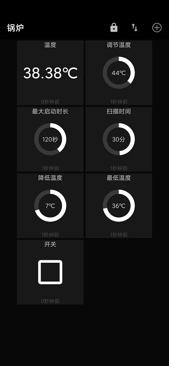
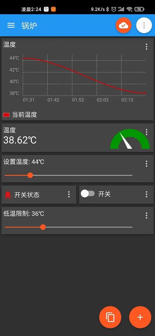
The core control logic is written in the ESP8266 module, which continuously collects temperature data and publishes it as a topic. The smartphone can subscribe to this topic to view the boiler temperature in real-time. In the loop, there is a variable for set temperature. If the collected temperature exceeds the set temperature, a switch topic is published to turn it on. If the temperature is below the set temperature, a switch topic is published to turn it off, and each time the subscribed set topic is used to modify the set temperature variable.
The ESP01 controls the relay, and each time it subscribes to the switch topic, it can operate accordingly, publishing the current switch status as a topic each time.
Initially, I wrote the code logic so that the smartphone only needed to publish the set temperature topic, but it still required manual adjustments periodically, failing to achieve full automation. Later, I modified the code logic in the ESP8266 to make it more complex.
The core logic of the ESP8266 still follows the above pattern. Each time the temperature exceeds the set temperature, it will turn on the switch. However, after activation, if the temperature drops below the set temperature, it will not immediately turn off the switch. Instead, it will wait until the temperature drops below the set temperature minus a variable before publishing a switch off topic. This is to prevent the switch from rapidly toggling on and off due to fluctuations around the set temperature. Here, I introduced a variable called temperature step. There is another issue: if the boiler continues to heat, even if the circulation pump is always on, the boiler temperature will not drop below the set temperature (the return pipe temperature is already above the set temperature). Therefore, I introduced a second variable: maximum startup duration. Each time it starts, I activate a timer. If the timer exceeds the maximum startup duration, the circulation pump will turn off regardless of whether the temperature is below the set temperature, and the set temperature will be increased. The increase will be the temperature step plus the current temperature, thus achieving automatic adjustment of the set temperature (in the upward direction). Another issue arises when the coal in the boiler is nearly burned out, causing the detected temperature to drop significantly below the set temperature, preventing the circulation pump from starting. Therefore, I introduced a third variable: callback detection time. When the ESP8266 powers on, it starts a timer. If the timer equals the callback detection time, the set temperature will be adjusted to the current temperature for automatic callback of the set temperature. Assuming the callback detection time is 30 minutes, even if the set temperature is higher than the detected temperature, the circulation pump will start every 30 minutes, creating a closed loop with the remaining logic to achieve automatic adjustment of the set temperature. I also added a variable called minimum temperature. If the current temperature is below the minimum temperature, the circulation pump will not start even if the current temperature is higher than the set temperature, preventing it from starting every 30 minutes regardless of the situation. The minimum temperature can be set slightly above the ambient temperature.
All these variables: set temperature, temperature step, maximum startup duration, callback detection time, and minimum temperature can be set via the smartphone. I made the ESP8266 subscribe to these topics to set these variables.
ESP8266 code:
from machine import Pin,reset
import onewire
from ds18x20 import DS18X20
import time
import tm1637
from umqtt.simple import MQTTClient

def main():
    client_id = "esp_temperature"
    mserver = '192.168.0.99'
    #mserver = '192.168.3.200'
    #mserver = 'mq.tongxinmao.com'

    tm = tm1637.TM1637(clk=Pin(14), dio=Pin(12))
    ow=onewire.OneWire(Pin(4))
    d = DS18X20(ow)
    rom = d.scan()

    def sub_callback(topic, msg):
        # print((topic, msg))
        nonlocal setTemperature
        nonlocal lowTemperature
        nonlocal startTime
        nonlocal scanTime
        nonlocal step

        nonlocal startTimeTemp
        nonlocal scanTimeTemp
        nonlocal switchStatus

        data = int(msg.decode())
        if topic == b'setTemperature':
            setTemperature = data
        elif topic == b"setLowTemperature":
            lowTemperature = data
        elif topic == b"setStartTime":
            startTime = data
            startTimeTemp = startTime

        elif topic == b"setScanTime":
            scanTime = data*60
            scanTimeTemp = scanTime

        elif topic == b"setStep":
            step = data
        elif topic == b"switchWell":
            switchStatus = data
        else:
            print("Error")

    def publishInfo():
        nonlocal client
        client.publish("setTemperatureR",str(setTemperature),retain=True)
        client.publish("setLowTemperatureR",str(lowTemperature),retain=True)
        client.publish("setStartTimeR",str(startTime),retain=True)
        client.publish("setScanTimeR",str(int(scanTime/60)),retain=True)
        client.publish("setStepR",str(step),retain=True)

    client = MQTTClient(client_id, mserver, 0)
    client.set_callback(sub_callback)
    client.connect()
    client.subscribe(b'setTemperature')
    client.subscribe(b'setLowTemperature')
    client.subscribe(b'setStartTime')
    client.subscribe(b'setScanTime')
    client.subscribe(b"setStep")
    client.subscribe(b"switchWell")

    showSet = True
    setTemperature = 40
    lowTemperature = 40
    startTime = 120 # Startup time
    scanTime = 1800 # 30 minutes
    step = 7

    switchStatus = 0 # 0 means off, 1 means on

    startTimeTemp = startTime
    scanTimeTemp = scanTime

    while True:
        try:
            d.convert_temp()
            # Display temperature and set temperature
            nowTemperature = d.read_temp(rom[0])
            if showSet:
                tm.temperature(int(setTemperature))
            else:
                tm.number(int(nowTemperature*10))

            if int(nowTemperature) >= setTemperature and (not switchStatus) and int(nowTemperature) > lowTemperature:# Start when above set temperature
                client.publish("switch",'1',retain=True)
                startTimeTemp = startTime

            if (int(nowTemperature) <= setTemperature - step) and switchStatus:
                client.publish("switch",'0',retain=True)

            if startTimeTemp <= 0: # If time exceeds 3 minutes, automatically stop and increase set temperature
                client.publish("switch",'0',retain=True)
                setTemperature = int(nowTemperature + step)
                startTimeTemp = startTime

            if switchStatus:
                startTimeTemp -= 1

            client.check_msg()
            client.publish("temperature",str(round(nowTemperature,2)),retain=True)
            publishInfo()

            if scanTimeTemp <= 0:
                setTemperature = int(nowTemperature - step) # Callback to lower temperature
                scanTimeTemp = scanTime
            scanTimeTemp -= 1

        except Exception as e:
            reset()

        time.sleep(1)
        showSet = not showSet
ESP01 code:
from machine import Pin
from umqtt.simple import MQTTClient
import time

def main():
    def sub_callback(topic, msg):
        nonlocal client
        nonlocal pin
        """
        Subscription message callback
        """
        if msg == b'0':
            pin.off()
        else:
            pin.on()
        client.publish("switchWell",str(pin.value()),retain=True)

    client_id = "switch_id"
    mserver = '192.168.0.99'
    #mserver = 'mq.tongxinmao.com'
    pin = Pin(0,Pin.OUT)

    client = MQTTClient(client_id, mserver, 0)
    client.set_callback(sub_callback)
    client.connect()
    client.subscribe(b'switch')
    while True:
        client.check_msg()
        client.publish("switchStatus",str(pin.value()),retain=True)
5. Client Monitoring and Adjustment Software
1. Mobile Client:
MQTT Dash:
IoTMQTTPanel:
I recommend using IoTMQTTPanel on mobile because it is convenient to publish a panel configuration to another phone. You only need to publish a topic, and the receiving end subscribes to a topic with the same name to transfer the entire panel. MQTT Dash also has this feature, but it freezes after publishing, and I don’t know why.
2. Desktop Client:
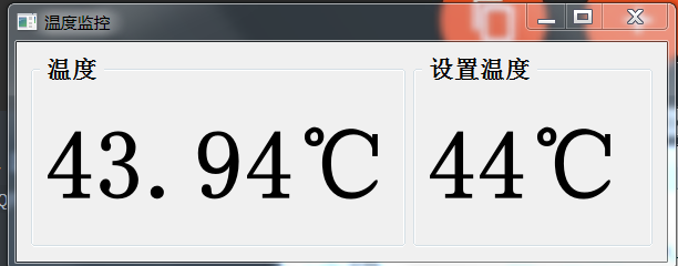
I am not sure what good software is available for the desktop, so I wrote a simple monitoring software using PyQt5, which does not have adjustment functionality because the devices were not stable at the time, so I focused on monitoring the operational status.
6. Conclusion
Currently, the entire system has been running stably for two weeks, and no manual adjustments are needed anymore. I spent a considerable amount of time resolving all issues, especially the LmacRxBlk:1 error, which took me a long time. Creating something practically useful from scratch is quite challenging, as some problems can only be exposed in real-world environments, such as the change in resistance value due to the rising temperature of the pull-up resistor. There are many details I haven’t mentioned, such as flashing firmware, 3D modeling of the casing, deploying the Mosquitto service on the Raspberry Pi, port forwarding, and too much content to elaborate on, so I can only briefly describe the main content and logic.
––OfficialForum
www.52pojie.cn
––RecommendtoFriends
PublicWeChatAccount:WoolLoveBreakForum
OrSearchWeChatAccount:pojie_52