This article presents the design of an alcohol concentration detector based on the current situation, which has the following advantages compared to traditional alcohol detectors: (1) Small size, easy to carry; (2) Uses a 12-bit AD conversion chip for high accuracy; (3) Samples 20 times within one cycle and performs smoothing on the sampled data in the software program, resulting in minimal error.
1 System Hardware Design
1.1 Detection Parameters
This system uses alcohol concentration as the main detection parameter. By detecting the voltage value of the alcohol signal acquisition circuit and performing a series of analysis and processing, the alcohol concentration value in the breath of the tested person can be obtained.
1.2 Scheme Design

Figure 1 is the hardware flowchart of this system, which includes the signal acquisition module, signal processing module, control processing module, and human-machine channel.
1.2.1 Signal Acquisition Module
The MQ-3 alcohol sensor is highly sensitive to alcohol signals in the range of 10 ppm to 1,000 ppm. Additionally, it has the following characteristics: short response time, quick recovery; long service life, stable measured values; and a simple drive circuit that is easy to apply.
The output circuit of the MQ-3 alcohol sensor is shown in Figure 2.
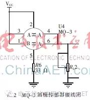
The MQ-3 has 6 pin-shaped leads, 4 of which are used for signal extraction, and the other 2 are used to provide heating current. In Figure 2, pins 1, 3, 4, and 6 are used for signal extraction, while pins 2 and 5 are for the heating resistor. At pin 5, a resistor of appropriate value needs to be connected to limit the current. When the micro A2O3 ceramic tube and SnO2 sensitive layer material on the MQ-3 encounter alcohol molecules, the resistance of the sensitive body between pins 3 and 4 changes, causing the output voltage value to change. This change is reversible, allowing the alcohol sensor to be reused and measured multiple times in practical applications. If powered by a 5 V supply, theoretically, the output voltage value of the MQ-3 sensor should be 0-5 V, but experiments show that in an alcohol-free environment, the output voltage value is not 0. This requires a zero-point setting for the system. For convenience in calculations, this system chooses a digital voltage value of 1,000 as the zero point for system detection. When the obtained digital voltage value is less than 1,000, the LCD cannot display the alcohol concentration value.
1.2.2 Signal Processing Module
The alcohol sensor converts the alcohol concentration signal into an analog voltage signal, which is then filtered and converted into a digital voltage signal for analysis by the control processing circuit. Figure 3 is the flowchart of the signal processing module.

(1) Filtering Circuit
The filtering circuit is used to remove any high-frequency interference signals that may be mixed in with the output voltage signal.
(2) AD Conversion Circuit
The voltage signal output from the sensor is an analog voltage signal after passing through the filtering circuit. To facilitate data processing by the microcontroller, it needs to be converted into a digital signal, so an AD conversion circuit is connected afterward. In the AD conversion circuit, a 12-bit ADS7886 chip is selected for its high precision, low power consumption, short conversion time, and simple interface, while being economically priced. The interface circuit between the ADS7886 and the microcontroller is shown in Figure 4.
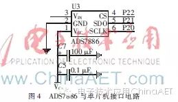
When the STC89C52 microcontroller is used with the ADS7886, the VCC connects to a 5 V voltage. The capacitor in the figure is a bypass capacitor used to remove high-frequency signals that may be mixed in VCC. The SCLK port generates a serial clock for data conversion, thus requiring a connection to the microcontroller clock; the CS port is the chip select signal. The VIN port is used for input signals, and the SDO port is used to receive digital signal data. The ADS7886 outputs data while performing conversions. This data includes four leading zeros followed by a 12-bit number.
(3) Control Processing Module
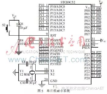
The control processing module mainly refers to the minimum system of the microcontroller. The microcontroller used in this system is the STC89C52 produced by STC, which is a low-power, high-performance CMOS 8-bit microcontroller with 8 KB of in-system programmable Flash memory. It also features non-decryptable programs, low cost, low power consumption, high-speed computation, strong reliability, strong anti-static and anti-interference capabilities, and powerful functionality. The minimum system of the microcontroller is shown in Figure 5.
1.2.3 Human-Machine Channel
The human-machine channel in this system mainly includes the key detection module, LCD display module, and sound and light alarm module.
(1) Key Detection Module
Measurement Key: The system starts to collect alcohol concentration signals only when the measurement key is pressed, followed by a series of analysis and processing operations.
Reset Key: After a measurement is completed, a reset operation is required before performing the next measurement; otherwise, it may cause significant errors.
RL Voltage Divider Resistor: Used for zero adjustment. When the designed circuit board is moved or when the MQ-3 alcohol sensor is in a highly interfering environment, the RL voltage divider needs to be adjusted with a screwdriver. When it is adjusted so that the LCD displays around 1,000, alcohol concentration measurement operations can proceed.
(2) LCD Display Module
The LCD1602 has low power consumption, small size, and low cost, and meets the requirements of this system design, so it is chosen as the display module for this design. Additionally, the LCD1602 has adjustable contrast, includes a reset circuit, and provides various control commands.
In this design, the LCD1602 display screen needs to show the real-time sampled digital voltage value and the size of the alcohol concentration value.
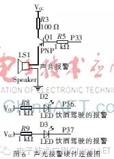
(3) Sound and Light Alarm Module
When the detected alcohol concentration exceeds 200 mg/L, the yellow indicator light D2 lights up, the buzzer sounds an alarm, and the current measured alcohol concentration is displayed on the LCD screen; when the detected alcohol concentration exceeds 800 mg/L, the red indicator light D3 lights up, the buzzer sounds an alarm, and the current measured alcohol concentration is displayed on the LCD screen. When the detected alcohol concentration is less than 200 mg/L, the LCD screen displays the alcohol concentration value, the alarm indicator light is off, and the buzzer does not sound. The sound and light alarm module is shown in Figure 6.
2 System Software Design
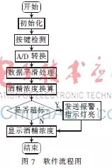
The system first processes the obtained digital voltage signal through a software program for data smoothing, sampling 20 times within one cycle, and using the average of the middle 10 sampling values as this alcohol signal sampling’s digital voltage value. Then, the change in alcohol concentration is calculated based on the ratio of the resistance of the MQ-3 sensitive body to the voltage of the voltage divider resistor RL. The system converts the processed data into alcohol concentration values and then displays them on the LCD1602. If the measured data exceeds the set standard threshold, the sound and light alarm module begins to operate. Additionally, the human-machine interaction function can be controlled through manual key operations. The software flowchart is shown in Figure 7.
3 Overall System Debugging
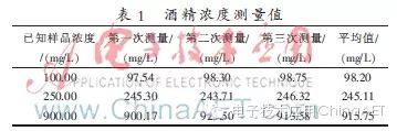
First, place the sensor in an alcohol-free environment, adjusting it so that the LCD1602 displays a concentration value of 0.00 mg/L. Within the detectable alcohol concentration range of the MQ-3, specifically from 10 ppm to 1,000 ppm, prepare three different concentrations of alcohol liquid and pre-calculate their concentration values. Then use a cotton swab dipped in the alcohol liquid and place it above the sensor. If the displayed value on the LCD is close to the prepared alcohol concentration values, the debugging is successful; if there is a large deviation between the displayed value and the prepared concentration value, the debugging is unsuccessful, and further investigation is needed. Table 1 shows the measured alcohol concentration values at 100 mg/L, 250 mg/L, and 900 mg/L. It can be seen that the measurement error of the alcohol concentration in this design is within 2%. With further optimization, it can be practically applied.
4 Conclusion
If this design is improved to a certain extent and integrated with various sensors, remote processing, and other technologies, it can be made into an “alcohol key.” Before opening the car door, the driver needs to press the door opening button, wait for the yellow preparation light to turn on, and blow into the blowing stick for about 2 seconds. If the result of the alcohol breath test conducted by the driver does not exceed the legally permissible standard value, the green indicator light turns on, successfully passing the alcohol test, and the car door can be opened for driving; if the result exceeds the legally permissible standard value, the red indicator light turns on, and the system will keep the engine in a stationary state, preventing it from starting, effectively curbing drunk driving. With the advancement of technology, it is believed that this alcohol detection technology will be more widely applied in our lives.