Su Wenhu, Chen Xun
(School of Electronic Information, Jiangsu University of Science and Technology, Zhenjiang, Jiangsu 212003, China)
Abstract: In response to the inability of traditional ultrasonic power supplies to drive and lock different resonant frequency transducers, which prevents phase locking and frequency tracking across a wide frequency range, a wideband ultrasonic power supply based on FPGA has been designed. This system features automatic frequency search and tracking, as well as dynamic matching of transducers with different resonant frequencies. A dynamic step size frequency search method was developed based on the impedance characteristic curve of the transducer, allowing for rapid tracking of the transducer’s resonant frequency. The output frequency is adjusted in real-time based on the phase difference between the voltage and current in the feedback circuit, ensuring the entire system operates in a resonant state. Experimental results indicate that the designed wideband ultrasonic power supply has fast frequency searching capabilities, accurate tracking, and good adaptability in dynamic matching of transducers.
Keywords: frequency search; frequency tracking; wideband ultrasonic power supply
Classification Number: TN86
Document Identification Code: A
DOI: 10.16157/j.issn.0258-7998.2017.03.014
Chinese Citation Format: Su Wenhu, Chen Xun. Design of a Wideband Ultrasonic Power Supply Frequency Tracking System Based on FPGA[J]. Application of Electronic Technique, 2017, 43(3): 59-62.
English Citation Format: Su Wenhu, Chen Xun. Research on frequency tracking system of wide-band ultrasonic power supply based on FPGA[J]. Application of Electronic Technique, 2017, 43(3): 59-62.
1 Introduction
Ultrasonic welding, cleaning, and detection technologies have broad application prospects. However, issues such as resonant frequency drift and tracking lag in ultrasonic systems have not been completely resolved. Currently developed ultrasonic devices typically consist of an ultrasonic power supply and its matching transducer, and a single ultrasonic power supply cannot drive and lock transducers across different resonant frequency bands, making frequency tracking and phase locking across a wide frequency range impossible. Therefore, developing a wideband ultrasonic power supply with automatic frequency tracking and dynamic matching of transducers with different resonant frequencies holds significant application value.
This paper employs the XILINX ZYNQ series FPGA (XC7Z0201CLG484I) as the main controller to design an ultrasonic power supply capable of automatic frequency search, tracking, and dynamic matching of transducers across a wide frequency range. The output frequency ranges from 20 to 40 kHz, allowing it to drive various types of transducers within this frequency range, demonstrating broad applicability.
2 Ultrasonic Power Supply System Composition
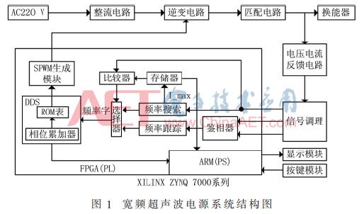
The ultrasonic power supply consists of a rectifier circuit, inverter circuit, matching circuit, feedback circuit, and main control circuit. The system structure block diagram is shown in Figure 1. The main controller FPGA integrates a dual-core ARM Cortex-A9 processor resource (Processing System, PS) and traditional Field-Programmable Gate Array (FPGA) logic resources (Programmable Logic, PL). The PL units of the FPGA primarily perform functions such as frequency search, frequency tracking, voltage and current phase detection, SPWM generation, and Direct Digital Synthesis (DDS). The PS processor handles interface display and input parameter processing. The matching circuit consists of a high-frequency transformer and an improved T-type matching network, which serves to adjust the load to a purely resistive state, thereby improving the efficiency of the power supply.
DDS can be simplified to consist of a phase accumulator and a ROM sine wave storage table. Under the control of the system clock, the frequency control word is updated, which corresponds to the address in the ROM sine wave table. The content stored at this address is the amplitude corresponding to a certain synthesis point of the sine wave. In the next system clock cycle, the output of the phase accumulator is increased by a frequency control word, which corresponds to changing the address of the waveform storage, thus generating the next amplitude point of the synthesized waveform until the phase accumulator overflows, forming a complete sine wave. The frequency of this sine wave changes with the frequency control word, and its output frequency is:
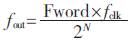
where N is the bit length of the phase accumulator, fclk is the system clock, and Fword is the frequency control word.
The DDS output sine wave signal is modulated with the high-frequency triangular carrier signal generated internally by the SPWM module, producing a PWM wave whose pulse width varies according to the sine wave pattern, controlling the inverter circuit to output frequency changes according to the sine wave frequency output by the DDS.
Upon powering the system, frequency search is first conducted based on the effective value of the feedback current I_in, quickly searching for the resonant frequency of the transducer within the 20 kHz to 40 kHz frequency range, and recording the maximum current value I_max at the resonant frequency as the current threshold. The frequency tracking program is then initiated, locking the output frequency at the frequency point where the voltage and current phases are consistent, while the PL also monitors the feedback current value in real-time against I_max as an auxiliary condition to determine whether the system is in a resonant state. If the system changes transducers or experiences a sudden load change that causes it to lose resonance, the feedback current value will be significantly lower than I_max. At this point, the PL will select the frequency search program to re-search for the resonant frequency of the transducer before switching to frequency tracking for phase locking.
3 Frequency Search
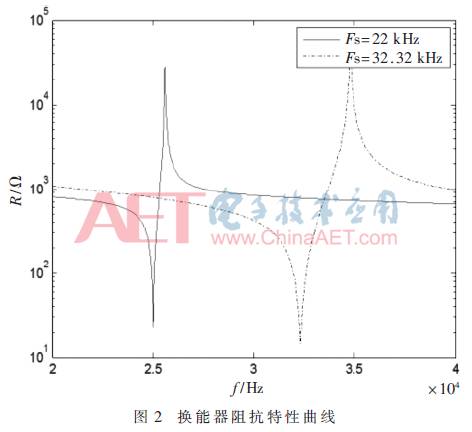
The ultrasonic power supply operates most efficiently when its output frequency matches the resonant frequency of the transducer, resulting in the most stable system operation. Experimental results show that when the transducer operates at the resonant frequency Fs, the current flowing through the load is maximized, thus the resonant frequency can be searched by detecting the current value of the transducer.
Figure 2 illustrates the impedance characteristic curves of transducers with resonant frequencies of 22 kHz and 32.32 kHz within the 20 kHz to 40 kHz frequency band. As shown in Figure 2, the impedance of the transducer undergoes significant changes near the resonant frequency, indicating a noticeable change in current value; conversely, when far from the resonant frequency, the impedance changes little, resulting in minimal current variation. Based on this impedance characteristic of the transducer, a frequency search method based on the maximum current value was designed on the FPGA platform. The FPGA implementation of the frequency search is shown in Figure 3.
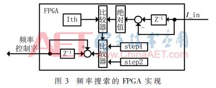
After powering on, the frequency search module generates the frequency control word required for a 20 kHz output frequency. Under the control of the system clock, the current effective value I_in is compared with the previous cycle’s feedback current value. If the difference between the two is less than the set threshold Ith, it indicates that the load current is changing insignificantly, and the system frequency is far from the resonant frequency of the transducer. In this case, the frequency control word of the DDS is changed by a large step size step1. When the difference is greater than Ith, it indicates that the system frequency is close to the resonant frequency of the transducer, and the frequency control word will be fine-tuned by a small step size step2 until the output frequency reaches 40 kHz, completing the frequency search function. The software flowchart for the frequency search is shown in Figure 4. The variables in the figure are annotated as follows:
(1) Freq: Search frequency range (20 kHz to 40 kHz)
(2) F_word_rem: Resonant frequency control word
(3) I_in: Input current effective value
(4) I_max: Maximum current value
(5) step, step1, step2: Represent different step sizes
(6) Ith: Set threshold
(7) det_I: Current difference between adjacent sampling periods.
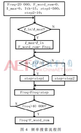
After powering on, the initial frequency Freq is set to 20 kHz. In each sampling period, the relationship between the input current I_in and I_max is compared. If the input current exceeds I_max, the input current value is assigned to I_max, and the corresponding frequency point is recorded as F_word_rem. The current values of adjacent sampling periods are then compared to generate det_I, which is subsequently compared with Ith. If det_I is greater than Ith, it indicates that the system’s output frequency is close to the resonant frequency point of the transducer, and the output frequency Freq will be adjusted downwards by a small step size step2; conversely, if the output frequency is far from the resonant frequency of the transducer, a large step size step1 will be used to change the output frequency across the wide frequency range. After completing the search within the frequency domain, the output frequency word corresponds to the resonant frequency point F_word_rem at which the current value was maximized, completing the frequency search program.
Figure 5 shows the ModelSim simulation diagram of the frequency search program. The cursor position represents the point of maximum current value, which is the resonant frequency point of the transducer. Near the resonant frequency of the transducer, the output frequency word changes in small steps of step=10, gradually searching for the resonant frequency point, recording the resonant frequency as 20,260 and the maximum current value at this point as 3,471. Figure 5 demonstrates that the variable step search method designed based on the impedance characteristic curve of the transducer meets the design requirements.
4 Frequency Tracking
When the system operates in a resonant state, the equivalent load of the transducer is purely resistive, and the phase difference between voltage and current is approximately zero. Therefore, the circuit’s resonant state can be determined by detecting the phase difference between voltage and current. During frequency tracking, the FPGA compares the feedback voltage and current signals to generate a voltage-current phase difference signal, which is used to adjust the output of the frequency control word, thereby changing the system output frequency until the phase difference between the feedback voltage and current approaches zero, locking the entire system at the resonant frequency of the transducer. The FPGA implementation of frequency tracking is shown in Figure 6.
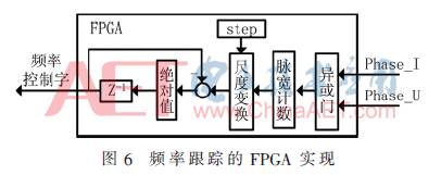
The output signals Phase_I and Phase_U from the feedback circuit represent the current and voltage phase signals of the transducer, respectively. After digital phase detection, the output phase difference between current and voltage is recorded by a pulse width counter, and the frequency control word of the DDS is adjusted based on the given step size step, changing the output frequency of the inverter circuit, thereby altering the phase difference between Phase_I and Phase_U until the system stabilizes at the resonant frequency point. The software flowchart for frequency tracking is shown in Figure 7.
After locating the resonant frequency F_word_rem, the system initiates the frequency tracking program, sending the value of F_word_rem to Freq as the output of the system frequency control word, while the FPGA collects the feedback voltage and current signals. When it detects that the current phase leads the voltage phase, it decreases the frequency control word Freq by the step size step; conversely, if the voltage phase leads the current phase, it increases the frequency control word, changing the system output frequency until the voltage and current phase difference is within the set margin.
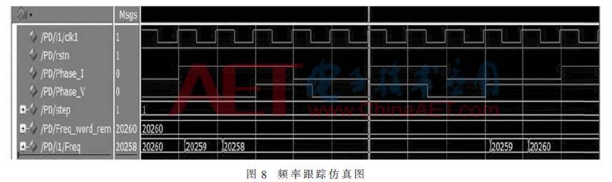
Figure 8 shows the ModelSim simulation diagram of the frequency tracking program, with the cursor position indicating the frequency point of zero phase difference between voltage and current. As shown in Figure 8, when the voltage phase leads the current phase, the output frequency control word Freq increases by a step size of 1 Hz based on the resonant frequency F_word_rem, corresponding to an increase in the PWM signal frequency driving the inverter circuit; conversely, when the current phase leads the voltage phase, the output frequency decreases accordingly until the feedback voltage and current phases are consistent.
5 Experimental Results
Using MATLAB R2014a, simulations of the designed system were conducted, taking a 20 kHz transducer as an example to analyze the phase difference of the feedback voltage and current signals, as shown in Figure 9.
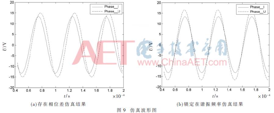
Figure 9(a) shows the voltage and current waveforms deviating from the resonant frequency point, where a certain phase difference exists. Upon initiating the frequency tracking program, the output frequency is adjusted to bring the voltage and current phase difference close to zero, as shown in Figure 9(b), where the phase difference is nearly zero. Experimental results indicate that the designed wideband ultrasonic power supply performs well in frequency tracking, with the transducer operating in a resonant state.
6 Conclusion
Based on the analysis of existing ultrasonic power supplies, a wideband ultrasonic power supply based on the XILINX ZYNQ 7000 series FPGA has been developed. After analyzing the characteristics of the transducer’s impedance characteristic curve, a variable step frequency search method was designed to quickly locate the resonant frequency point of the transducer. The system output frequency is locked at the resonant frequency based on the voltage and current phase difference. The designed ultrasonic power supply features fast frequency searching, accurate tracking, and dynamic matching of transducers with different resonant frequencies. The extensive resources integrated within the FPGA chip reduce the complexity of peripheral circuits, simplifying and stabilizing hardware design. Experimental results demonstrate that the designed wideband ultrasonic power supply can drive the transducer to operate in a resonant state, ensuring stable operation and low temperature, while performing well in frequency tracking and meeting design requirements.
References
[1] Zhou Wei, Zhang Dongquan. Research and development of ultrasonic frequency dual closed-loop control[C]. International Conference on Digital Manufacturing and Automation, 2012.
[2] Li Changyou. Research on the application of ultrasonic power supply frequency tracking system[J]. Power Electronics Technology, 2014, 48(3): 35-38.
[3] Dong Huijuan, Wu Jian, Zhang Guangyu, et al. An improved phase-locked loop method for automatic resonance frequency tracing based on static capacitance broadband compensation for a high-power ultrasonic transducer[J]. IEEE Transactions on Ultrasonics, Ferroelectrics and Frequency Control, 2012, 59(2): 205-210.
[4] Zhang Xinghong, Cai Wei, Qiu Lei, et al. Design of an adjustable ultrasonic driving power supply based on FPGA and DDS technology[J]. Instrument Technology and Sensor, 2015(6): 84-87.
[5] Hu Wulin, Cao Biao, Yang Jingwei. Frequency tracking and adjustment of ultrasonic welding power supply[J]. Electric Welder, 2014, 44(7): 47-51.
[6] Tang Xinxing. Development of ultrasonic power supply based on frequency automatic tracking and amplitude constant control[D]. Beijing: Beijing Jiaotong University, 2014.
[7] Qu Baida. Frequency tracking system for ultrasonic transducer based on DSP[J]. Piezoelectric and Acousto-optic, 2014, 36(2): 297-301.
[8] Shiang-Hwua Yu, Yi-Fei Hsieh, Pei-Ying Lai, et al. FPGA-based resonant-frequency-tracking power amplifier for ultrasonic transducer[C]. International Conference on Applied Electronics, 2015.
[9] Liu Xiaoguang, Liu Pingfeng, Jiang Xiaoming, et al. Research on frequency tracking of ultrasonic welding power supply based on FPGA[J]. Automation and Information Engineering, 2015, 36(4): 39-43.