Design and Simulation of a Pressure and Temperature Control System Based on the 51 Microcontroller
Introduction
In the fields of industrial automation and environmental monitoring, precise control of temperature, humidity, and pressure is crucial. This article will detail the design and implementation of a pressure and temperature control system based on the 51 microcontroller, including a complete Proteus simulation scheme and code analysis.
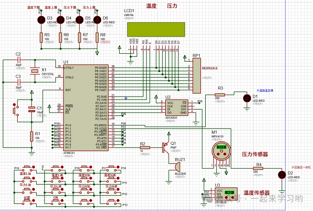
Circuit Diagram:
Code Access: https://mbd.pub/o/bread/YZWXk5ZwaA==
Or click to read the original text
System Overview
This system uses the STC89C51 microcontroller as the main controller, collecting environmental data through the DS18B20 temperature sensor and the ADC0832 analog-to-digital converter (for pressure detection). It uses an LCD1602 display to show measurement values and alarm thresholds in real-time, and controls heating/cooling devices and pressure regulation devices through relays.
Hardware Design
Main Components
-
Main Controller: STC89C51 Microcontroller
-
Temperature Sensor: DS18B20 (One-Wire Digital Temperature Sensor)
-
ADC Converter: ADC0832 (8-bit Dual-Channel A/D Converter)
-
Display Module: LCD1602 Liquid Crystal Display
-
Actuators: Relay-controlled heating/cooling devices, pressure regulation devices
-
Alarm Device: Buzzer and LED indicator
-
Input Device: 4×4 Matrix Keyboard
Proteus Simulation Circuit Design
The simulation circuit built in Proteus includes the following main components:
-
Microcontroller Minimum System (Crystal Oscillator, Reset Circuit)
-
DS18B20 Temperature Sensor Interface
-
ADC0832 Analog Signal Acquisition Circuit
-
LCD1602 Display Interface
-
Relay Driver Circuit
-
Matrix Keyboard Interface
-
Sound and Light Alarm Circuit
Software Design
Core Function Implementation
1. Matrix Keyboard Scanning
uchar key_scan() // Key Detection { uchar i, j; i = 0; j = 0; P1 = 0x0f; if(P1 != 0x0f) // Check if pressed { switch(P1) // Check rows { case 0x0e: i = 1; break; case 0x0d: i = 5; break; case 0x0b: i = 9; break; case 0x07: i = 13; break; } P1 = 0xf0; switch(P1) // Check columns { case 0xe0: j = 0; break; case 0xd0: j = 1; break; case 0xb0: j = 2; break; case 0x70: j = 3; break; } while(P1 != 0xf0); // Wait for key release } return i + j; }2. Main Control Logic
void main() { uchar key = 0; // Key value hang2[5] = 0xdf; // Temperature unit symbol Ds18b20Init(); // Sensor initialization init_1602(); // LCD initialization // Timer 0 initialization TMOD |= 0X01; TH0 = 0X3C; // 50ms timer TL0 = 0XB0; ET0 = 1; // Enable Timer 0 interrupt EA = 1; // Enable global interrupt TR0 = 1; // Start timer while(1) { key = key_scan(); // Key detection if(key == 13) // Mode switch key mode = 1; if(key == 14) mode = 0; if(mode == 1) // Setting mode { // Water level threshold setting if(key == 1) if(water_L < water_H) water_L++; if(key == 2) if(water_L > 0) water_L--; if(key == 3) if(water_H < 100) water_H++; if(key == 4) if(water_H > water_L) water_H--; // Temperature threshold setting if(key == 5) if(wendu_L < wendu_H) wendu_L++; if(key == 6) if(wendu_L > 0) wendu_L--; if(key == 7) if(wendu_H < 100) wendu_H++; if(key == 8) if(wendu_H > wendu_L) wendu_H--; // Pressure threshold setting if(key == 9) if(press_L < press_H) press_L++; if(key == 10) if(press_L > 0) press_L--; if(key == 11) if(press_H < 100) press_H++; if(key == 12) if(press_H > press_L) press_H--; } }}3. Timer Interrupt Service Routine
void Timer0() interrupt 1 { uchar i; if(time < 10) // Measure once every 0.5s time++; else { time = 0; // Data acquisition water = ADC(1); // Measure water level press = ADC(2); // Measure pressure wendu = Ds18b20ReadTemp(); // Read temperature // Alarm judgment and control i = 0; if(press > press_H) // Pressure too high { i++; led6 = 0; moter_press = 1; // Start pressure regulation } else { led6 = 1; moter_press = 0; // Stop pressure regulation } // Other alarm judgments are similar... // Buzzer control if(i > 0) beep = 0; // Alarm, buzzer sounds else beep = 1; // No alarm, buzzer stops // Display update hang2[2] = wendu/100 + 0x30; // Temperature hundredths hang2[3] = wendu%100/10 + 0x30; // Temperature tenths hang2[4] = wendu%10 + 0x30; // Temperature units hang2[10] = press/100 + 0x30; // Pressure hundredths hang2[11] = press%100/10 + 0x30; // Pressure tenths hang2[12] = press%10 + 0x30; // Pressure units // Mode selection display if(mode == 0) // Measurement mode { write_string(1, 0, hang1); write_string(2, 0, hang2); } else // Setting mode { // Display temperature threshold hang3[0] = 'T'; hang3[1] = wendu_H/100 + 0x30; hang3[2] = wendu_H%100/10 + 0x30; hang3[3] = wendu_H%10 + 0x30; write_string(1, 6, hang3); // Other threshold displays are similar... } } TH0 = 0X3C; // Reload timer initial value TL0 = 0XB0;}System Features
-
Dual Operating Modes: Free switching between measurement mode and setting mode
-
Multi-parameter Monitoring: Simultaneous monitoring of temperature, pressure, and water level
-
Adjustable Thresholds: Users can set alarm thresholds for various parameters via the keyboard
-
Automatic Control: Automatically controls related devices based on measurement values
-
Sound and Light Alarm: Triggers LED and buzzer alarms when limits are exceeded
-
Real-time Display: LCD displays measurement values and set parameters in real-time
Proteus Simulation Considerations
-
Ensure all component libraries are correctly installed
-
DS18B20 and ADC0832 need to use the correct simulation models
-
Relay driver circuit should include appropriate flyback diodes
-
During simulation, adjust sensor analog input values to test various scenarios
Conclusion
This article provides a detailed introduction to the design and implementation of a pressure and temperature control system based on the 51 microcontroller, offering a complete Proteus simulation scheme and code analysis. The system has good scalability, allowing for the addition of more sensors or control functions based on actual needs. Through this design, readers can learn about the comprehensive application of the 51 microcontroller, the use of various sensors, and the implementation methods of automatic control systems.