1. Introduction
1.1 Project Overview
[1] Project Functions
With the acceleration of global agricultural modernization and the development and application of advanced technologies such as the Internet of Things and artificial intelligence, smart agriculture has become a new trend in modern agricultural development. Smart agricultural systems based on precise perception, intelligent control, and remote management can significantly improve crop production efficiency, reduce resource consumption, and achieve environmentally friendly sustainable agricultural production.
In this context, China is vigorously promoting the construction of digital villages, and the smart agriculture management system, as an important component, plays a vital role in improving the precision management level of agricultural production and addressing issues such as untimely information acquisition, high labor management costs, and lack of scientific basis for decision-making in traditional agriculture.
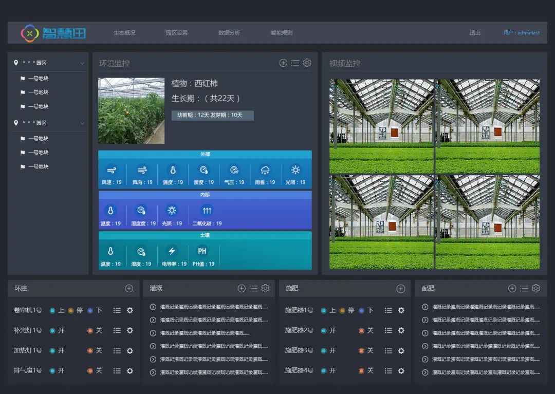
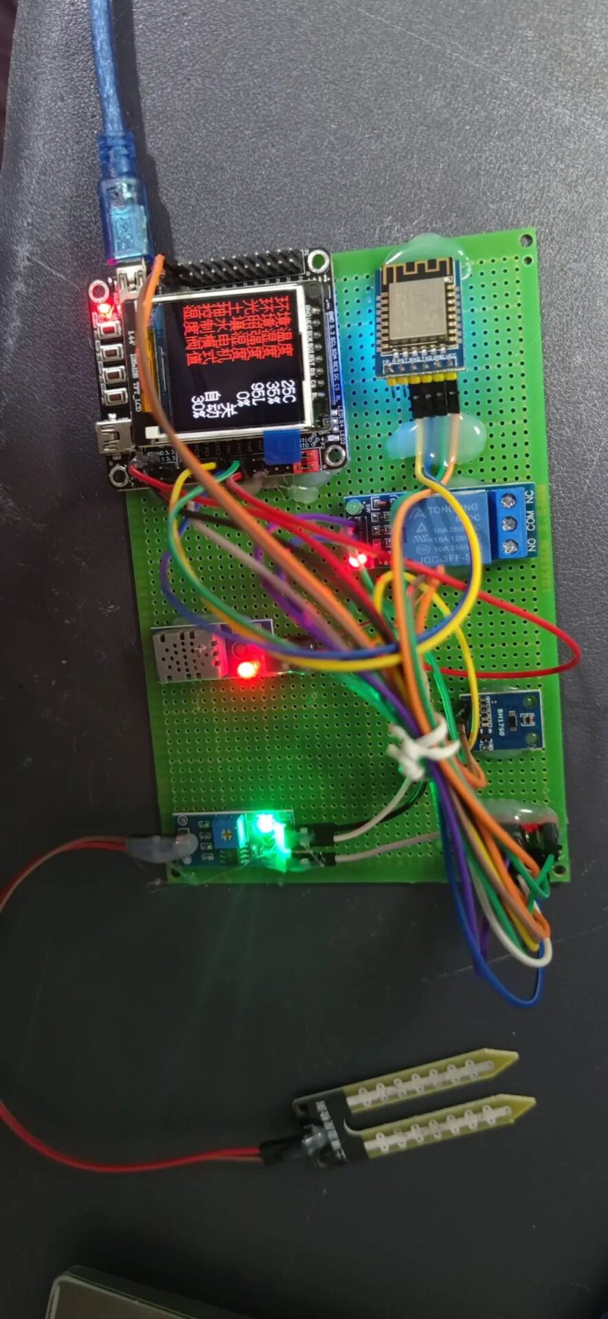
This design develops a smart agriculture management system based on the STM32F103RCT6 main control chip, which integrates DHT11 temperature and humidity sensor, BH1750 light intensity sensor, and soil moisture detection sensor to monitor the farmland environment and crop growth status in real-time. When parameters exceed the threshold, an alarm will be triggered through a buzzer to remind management personnel to perform irrigation, fertilization, and other operations. Meanwhile, using NBIoT communication technology (BC26 module), the collected data is uploaded to the cloud, utilizing the EMQX open-source MQTT server framework deployed on Huawei Cloud ECS server to achieve remote data display and processing.
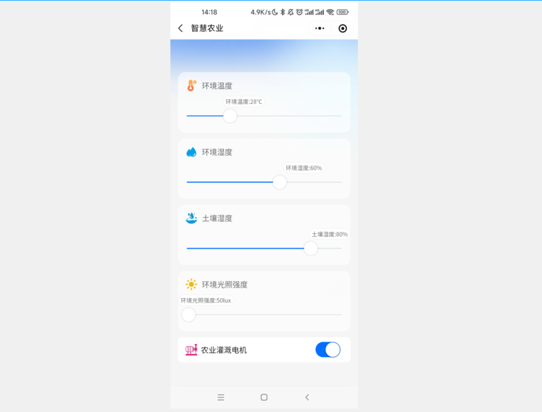
The system supports remote control functions via WeChat mini-programs, allowing farmers or managers to view farmland environmental parameters, receive early warning information anytime and anywhere, and remotely control irrigation equipment, supplementary lights, etc., greatly improving the intelligence and convenience of agricultural production. The implementation of this project not only helps promote the informatization level of agriculture in China but also facilitates the efficient use of agricultural resources, which is of great significance for ensuring national food security and promoting agricultural efficiency and farmers’ income.
[2] Functions of Design and Implementation
(1) Real-time Environmental Monitoring: The system uses integrated DHT11 temperature and humidity sensor, BH1750 light intensity sensor, and soil moisture detection sensor to monitor key parameters such as temperature, humidity, light intensity, and soil moisture content in the farmland environment in real-time. When these parameters exceed or fall below preset thresholds, the system will automatically trigger a buzzer alarm to remind management personnel to pay attention and take appropriate measures.
(2) Automated Management and Early Warning: Based on data detected by the soil moisture sensor, if the soil moisture is below the set threshold suitable for crop growth, the system will automatically remind the manager to perform irrigation operations. At the same time, fertilization reminders can be sent according to preset cycles to ensure that crops receive sufficient moisture and nutrients at the optimal time.
(3) Remote Control Function: Using NBIoT communication technology (BC26 module), the data collected on-site is uploaded to the cloud MQTT server and accessed and displayed remotely through the WeChat mini-program. Users can view real-time monitoring data and manually control farmland equipment remotely, such as starting or stopping a 5V water pump for irrigation or turning on or off white LED supplementary lights to adjust lighting conditions.
(4) Data Upload and Analysis: The MQTT server built on the EMQX open-source MQTT server framework can receive and process agricultural environmental data transmitted from the STM32 main control board and interface with the WeChat mini-program platform to provide users with intuitive and understandable data charts and analysis results, facilitating scientific decision-making and precise management by farmers or agricultural technicians.
[3] Project Hardware Module Composition
(1) Main Control Module: The STM32F103RCT6 microcontroller is used as the core control unit, responsible for the operation and management of the entire system. The STM32F103RCT6 has a rich set of peripheral interfaces, strong processing capabilities, and low power consumption characteristics, enabling real-time processing of sensor data, performing logical judgments, and sending and receiving instructions via wireless communication modules.
(2) Environmental Monitoring Module:
-
Temperature and Humidity Monitoring: The DHT11 temperature and humidity sensor is used to collect temperature and humidity information from the farmland environment.
-
Light Intensity Monitoring: The BH1750 light intensity sensor is used to measure the light intensity in the farmland.
-
Soil Moisture Detection: The soil moisture detection sensor is used to obtain soil moisture data in the crop growth area.
(3) Control Output Module:
-
Supplementary Light Control: A white LED light is configured as a supplementary light source, which can be intelligently adjusted or controlled remotely through the STM32 main control board based on light intensity monitoring results.
-
Irrigation System Control: A 5V water pump is used in conjunction with a relay to achieve irrigation functionality. When the soil moisture is below the preset threshold, the STM32 main control board will close the relay to start the water pump for irrigation; otherwise, it will stop irrigation.
(4) Wireless Communication Module: The NBIoT-BC26 module is integrated to achieve data interaction with the cloud server. This module features wide coverage, low power consumption, and large connectivity, ensuring stable data transmission to the MQTT server in various complex agricultural environments.
(5) Alarm Module: The system is equipped with a buzzer for alarm in abnormal situations. When environmental parameters exceed the set range, the main control board will drive the buzzer to emit a sound alarm.
1.2 Design Idea
(1) System Requirement Analysis: Based on the actual needs of smart agriculture management, key environmental parameters (temperature, humidity, light intensity, and soil moisture) that need to be monitored, as well as necessary control functions (irrigation, supplementary light control, etc.) are determined. At the same time, considering the need for remote monitoring and early warning, it is planned to achieve data upload and remote control through NBIoT communication technology.
(2) Hardware Selection and Design:
-
The main control chip is selected as STM32F103RCT6, as it has rich peripheral interfaces, strong processing capabilities, and low power consumption characteristics, which can meet the requirements for real-time data collection and control of the system.
-
DHT11 is selected as the temperature and humidity sensor, BH1750 as the light intensity sensor, and soil moisture detection sensor to obtain the basic information of the farmland environment.
-
An irrigation system is designed using a 5V water pump in conjunction with a relay to respond to soil moisture monitoring results.
-
A white LED light is used as a supplementary light source, which is connected to the main control board for intelligent adjustment or remote control.
-
A buzzer is equipped for alarm in abnormal situations.
-
The NBIoT-BC26 module is selected to ensure stable and reliable wireless communication, achieving data upload to the cloud.
(3) Software Architecture Design:
-
Develop an embedded software program for STM32, responsible for reading data from each sensor, executing logical judgments, such as triggering alarms when environmental parameters exceed limits, automatically or manually controlling irrigation based on soil moisture, and periodically reminding fertilization operations.
-
The NBIoT communication protocol stack is implemented to send the data collected on-site to the cloud MQTT server via the BC26 module.
-
The EMQX open-source MQTT server framework is deployed in the cloud to receive and store data sent from front-end devices.
-
A WeChat mini-program client is developed to interface with the MQTT server, displaying real-time monitoring data of the farmland environment and providing a remote manual control interface.
1.3 Sensor Function Introduction
(1) DHT11 Temperature and Humidity Sensor:
-
Function: Used for real-time monitoring of temperature and relative humidity in the farmland environment.
-
Features: DHT11 is a low-cost, low-power digital temperature and humidity composite sensor that provides an integrated solution. It can directly output calibrated digital signals, making it easy for microprocessors to read without complex signal processing circuits.
(2) BH1750 Light Intensity Sensor:
-
Function: Measures the light intensity (illuminance) in the farmland or greenhouse to determine whether current lighting conditions meet the growth needs of crops.
-
Features: BH1750 is a digital light intensity sensor with I²C interface, featuring high precision and wide range, capable of accurately detecting light intensity and supporting multiple resolution modes switching to adapt to different application scenarios.
(3) Soil Moisture Detection Sensor:
-
Function: Used to monitor the moisture content of the soil in the planting area, serving as an important basis for determining whether to irrigate.
-
Features: These sensors usually use capacitive, resistive, or frequency domain reflection (FDR) principles to detect soil moisture, converting it into electrical signal changes to achieve non-destructive measurement of soil moisture content. Their characteristics reflect the actual moisture status of the soil, helping to achieve precise irrigation.
(4) Buzzer Alarm Module:
-
Function: Although not a traditional sensor, it is used as an alarm device in this system. When environmental parameters exceed preset thresholds, the main control chip STM32 controls the buzzer to emit sound alarms, reminding management personnel to address abnormal situations in a timely manner.
(5) 5V Water Pump and Relay Combination:
-
Function: The water pump and relay work together to achieve irrigation functionality. The relay controls the on/off state of the water pump based on data feedback from the soil moisture sensor, achieving intelligent irrigation.
-
Features: As an electronic switch, the relay can remotely control large current devices such as water pumps, achieving small current control over large currents while isolating the electrical connection between the main controller and the load, improving the safety of the system.
(6) NBIoT-BC26 Module:
-
Function: As an IoT communication component, it is responsible for wirelessly transmitting various collected data to the cloud server while also receiving control commands from the cloud, achieving remote data interaction and control.
-
Features: NBIoT (Narrowband IoT) technology has advantages of low power consumption, wide coverage, and large connectivity, making it particularly suitable for smart agriculture scenarios requiring large-scale deployment and stable network connections. The BC26 module is a communication module based on NBIoT standards, with good network compatibility and stability.
1.4 Selection of Development Tools
The programming language for STM32 is C language, which has high execution efficiency. The C language compiled executable files are closest to machine code, while assembly language has the highest execution efficiency but poor portability. Currently, some operating system kernels and low-spec microcontrollers still use it frequently, but ordinary microcontroller programming mainly uses C language. The execution efficiency of C language is second only to assembly, with simple syntax, strong code universality, and cross-platform support, making it widely used in embedded low-level and microcontroller programming. The current design is developed using C language.
The development tool selected is Keil, a world-leading embedded microcontroller software developer, which was acquired by ARM in 2015. Since the current chip is the STM32F103 series, STM32F103 belongs to ARM’s chip architecture and Cortex-M3 core series, so using Keil to develop STM32 has inherent advantages. Keil is also widely used in many universities, and many textbooks use it for teaching, including development for 51 microcontrollers, STM32 microcontrollers, etc. Currently, there are other software options for MCU chip development, such as IAR, which is also widely used in MCU microprocessor development, offering stronger extensibility and supporting STM32 development and other chips, such as CC2530 and 51 microcontroller development. From the software usage perspective, IAR is simpler than Keil, with relatively fewer functions. If someone has used Keil frequently before, they might find it a bit uncomfortable to use IAR due to interface differences.

2. EMQX Open Source MQTT Server Framework
EMQX is an open-source, cloud-native distributed IoT MQTT message server designed to achieve high reliability and support massive MQTT connections for IoT terminals, as well as low-latency message routing among massive IoT devices. Developed based on the Erlang/OTP platform, it fully leverages the soft real-time, low-latency, and distributed characteristics of Erlang/OTP.
Here is a detailed introduction to the EMQX server framework:
(1) Scalability: EMQX supports billions of MQTT service subscriptions, with a single node capable of supporting 5 million MQTT device connections, and the cluster can scale to 100 million concurrent MQTT connections. This powerful scalability allows it to adapt to IoT applications of different scales.
(2) Security: EMQX provides multiple security mechanisms, including SSL/TLS, password authentication, enhanced authentication, and ACL (Access Control List), to ensure the security of data transmission and access.
(3) Rule Engine: EMQX has a built-in SQL-based rule engine that can filter, transform, and process messages in real-time, providing flexible message processing mechanisms. This allows applications to flexibly handle messages according to business needs.
(4) Data Storage: The enterprise version of EMQX also provides data storage capabilities, recording client online/offline status, subscription relationships, offline messages, message content, and message receipts into various databases. This feature preserves data in case of service crashes or client abnormal disconnections, ensuring data integrity and reliability.
(5) Cluster Design: EMQX adopts a Masterless large-scale distributed cluster architecture, achieving high availability and horizontal scalability of the system. The cluster design includes maintaining subscription tables, routing tables, and topic trees to achieve message forwarding and delivery to subscribers on various nodes.
(6) Protocol Support: EMQX fully supports MQTT 5.0 and 3.x protocol standards, providing better scalability, security, and reliability. It also supports various other protocols such as WebSocket, TCP, SSL/TLS, etc.
(7) Usability: EMQX provides rich APIs and plugin management features, allowing users to easily view online client information, kick out clients, manage plugin statuses, etc. It also offers a visual management interface and debugging tools for user monitoring and management.
3. Purchase ECS Cloud Server
3.1 Log in to the Official Website
https://www.huaweicloud.com/
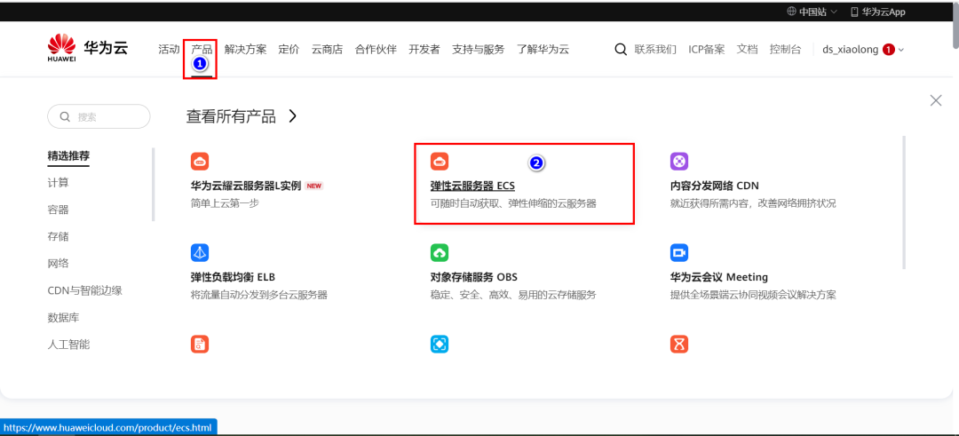
3.2 Purchase ECS Server
[1] Choose ECS Elastic Server
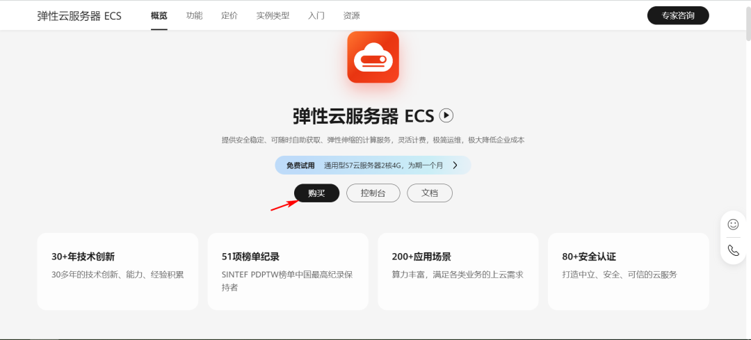
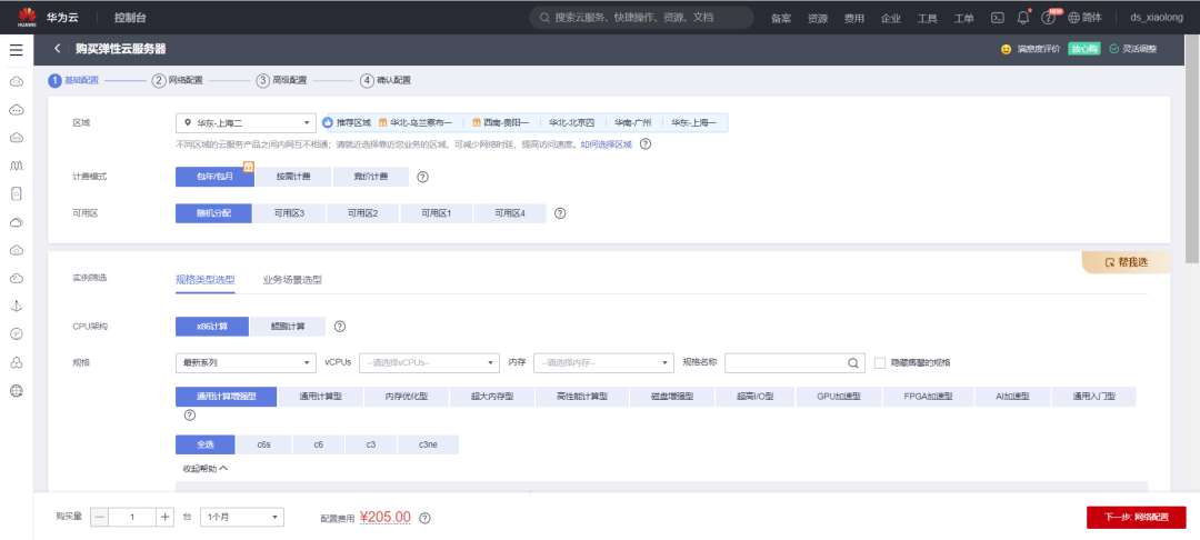
[2] Select the region, configuration information, and operating system for the ECS server (I chose Ubuntu 18.04 64-bit).
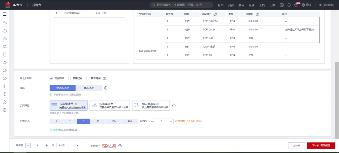
[3] Purchase an elastic public IP and configure bandwidth.
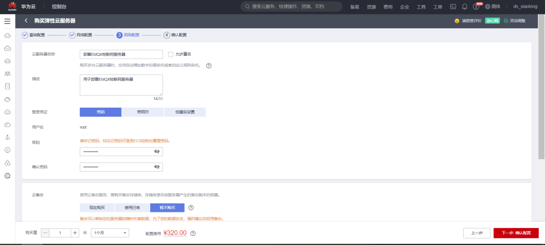
[4] Configure the password
[5] Choose the purchase duration; I chose a 1-month duration
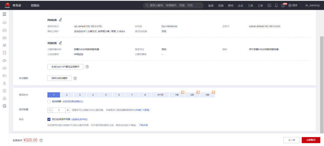
[6] Confirm payment
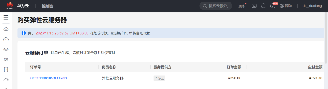
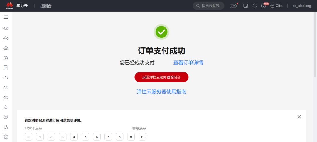
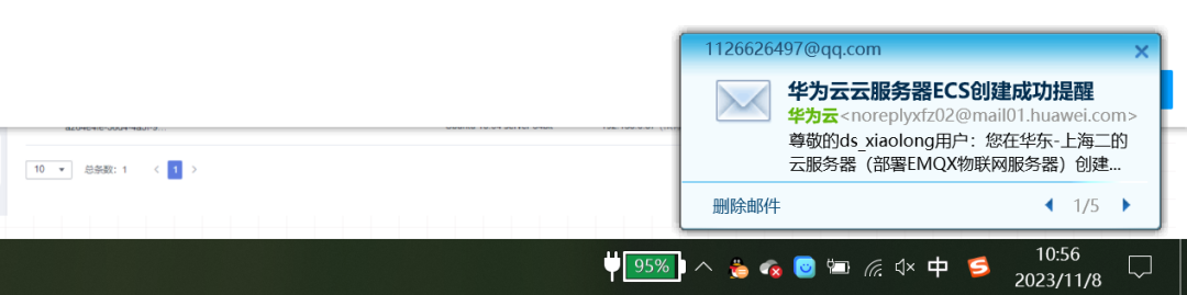
Received an email reminder, the server was created successfully. (To write the tutorial, I spent 320 yuan to buy a one-month server)
[7] Return to the elastic server control console
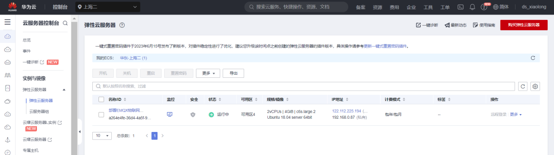
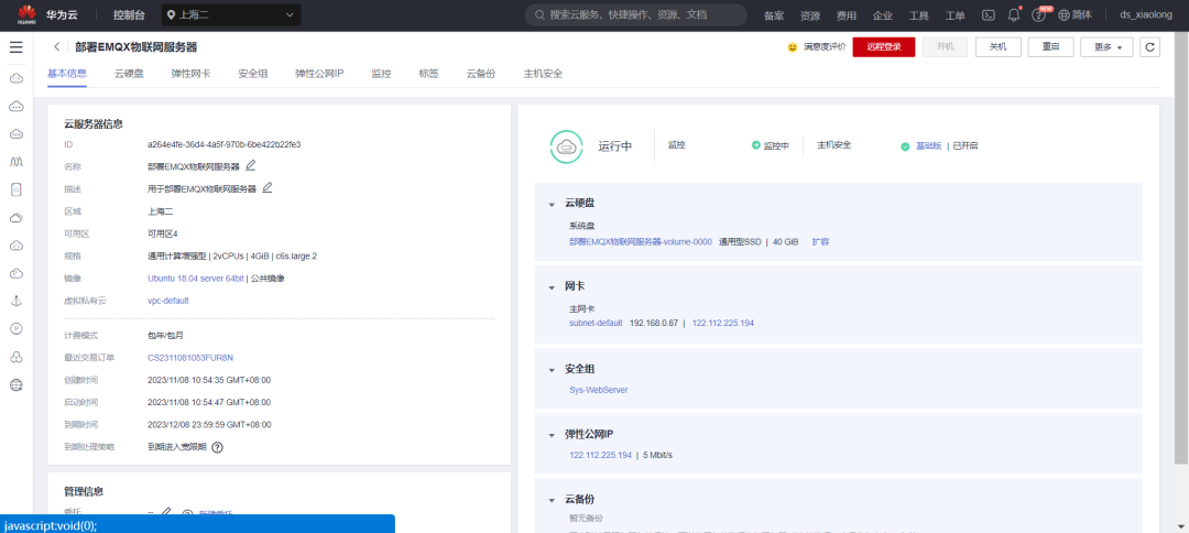
[8] Click on the server name to enter the details page.
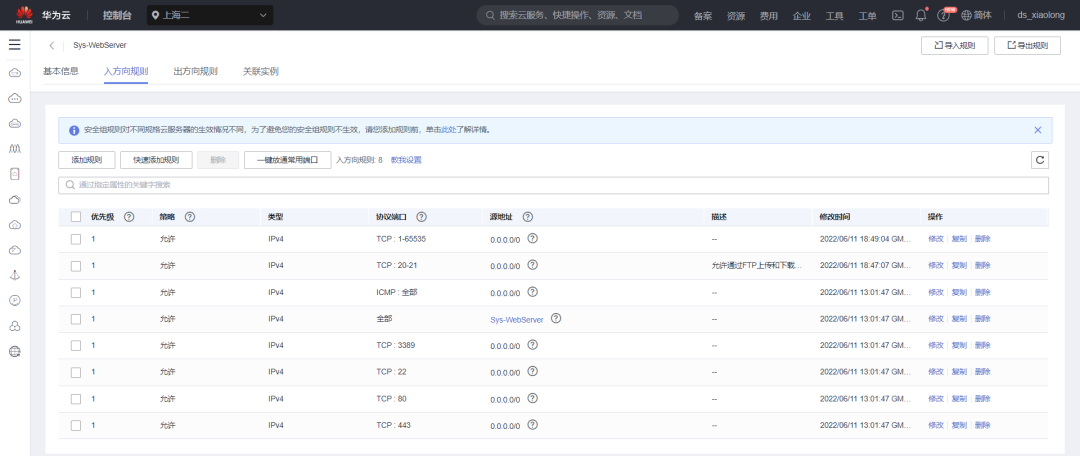
3.3 Configure Security Group
Ensure that several commonly used ports for the MQTT server are open.
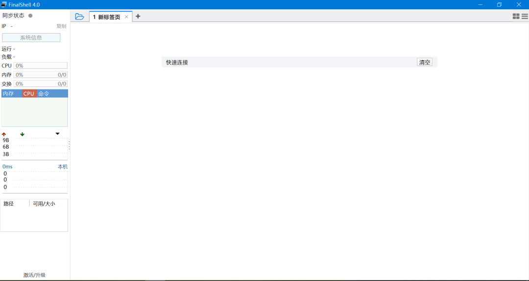
3.4 Install FinalShell
Install FinalShell terminal on Windows for convenient SSH protocol remote login to the cloud server. (Of course, using other methods to log in is also fine)
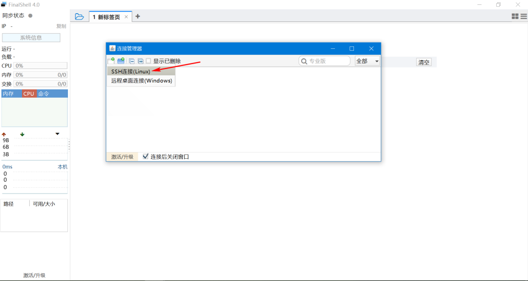
3.5 Remote Login to Cloud Server Terminal
[1] Create a new connection and select SSH connection.
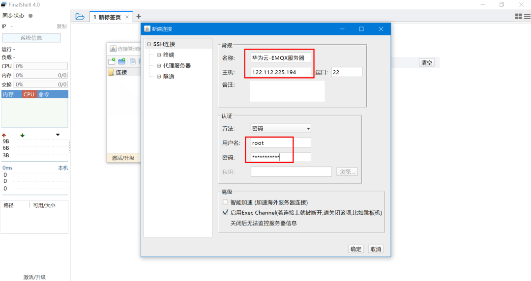
[2] Fill in the IP address, username, and password
The host is the public IP address of the server, the password is the one entered when creating the server, and the username is simply root.
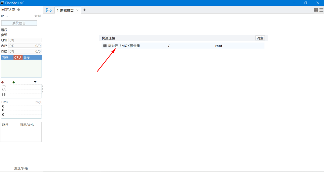
[3] Click to connect to the server
[4] The first login will pop up a prompt window. Select accept and save
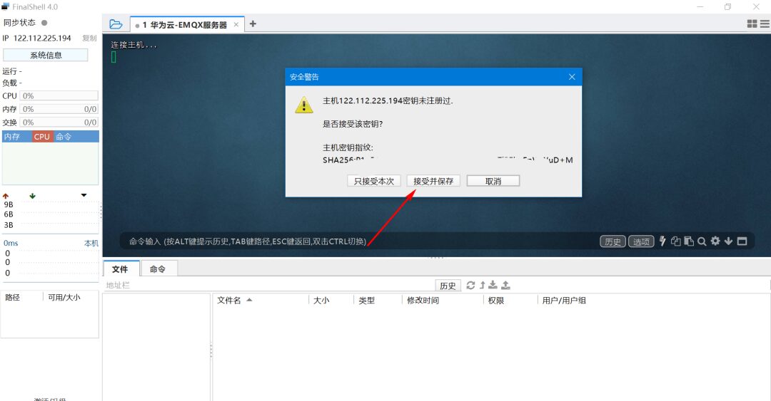
[5] Next, you can see that the server has successfully logged in.

4. Installing EMQX on Linux
This chapter will introduce how to download, install, and start EMQX on the Ubuntu system.
Supported Ubuntu Versions:
-
Ubuntu 22.04
-
Ubuntu 20.04
-
Ubuntu 18.04
4.1 Official Website Address
Link: https://www.emqx.io/docs/zh/v5.2/deploy/install-ubuntu.html
4.2 Install via Apt Source
EMQX supports installation via Apt source, eliminating the need for users to manually handle dependency relationships and update software packages, offering more convenience, security, and ease of use.
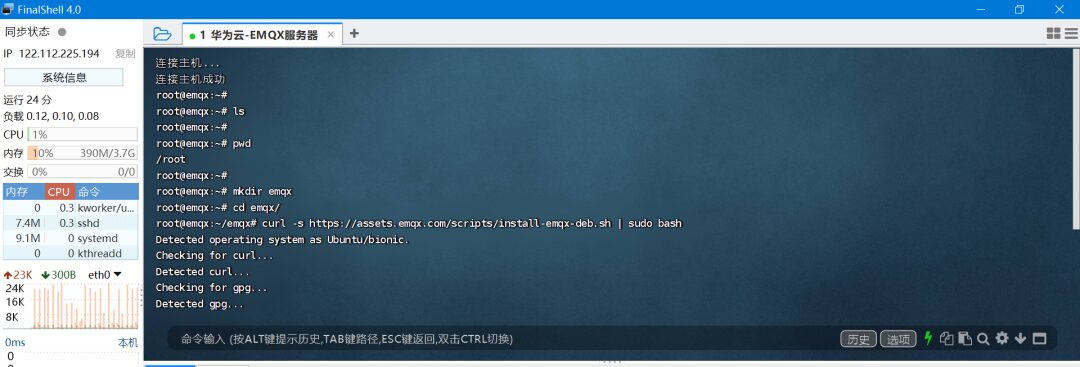
In the command line terminal, copy the command below and press enter.
[1] Configure the EMQX Apt source with the following command:
bash
curl -s https://assets.emqx.com/scripts/install-emqx-deb.sh | sudo bash
[2] Run the following command to install EMQX:
sudo apt-get install emqx
[3] Run the following command to start EMQX:
sudo systemctl start emqx
The process is as follows:
4.3 Common Commands for EMQX
cpp
sudo systemctl emqx start    Start
sudo systemctl emqx stop     Stop
sudo systemctl emqx restart  Restart
5. Configuring EMQX Server
5.1 Log in to EMQX Built-in Management Console
EMQX provides a built-in management console, the EMQX Dashboard, allowing users to easily manage and monitor the EMQX cluster and configure and use various features through a web page.
Enter in the browser: http://122.112.225.194:18083 to access the EMQX backend management page. You can manage connected clients or check the running status.
The IP address here is your ECS cloud server’s public IP address.
The effect of opening the address in the browser is as follows:
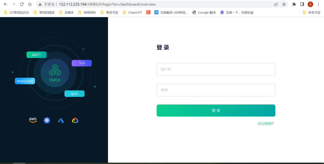
Default Username and Password:
Username: admin
Password: public
The first time you log in, you will be prompted to change the password. If you don’t want to set it, you can choose to skip it (for public server deployment, it’s safer to change the password).
Below is the new password modification:
The display of the login success page is as follows:
5.2 MQTT Configuration
Here you can configure some parameters of MQTT according to your needs.
5.3 Test MQTT Communication
Create a new client and click connect.
After connecting, click subscribe and publish. If the messages below can be received normally, it indicates that the MQTT server communication is functioning properly.
This page also shows the formats for topic publishing and topic subscription.
5.4 MQTT Client Login Server Test
Next, open our own MQTT client to log in to the MQTT server for testing data communication.
Select port: 1883
Fill in the parameters according to the software parameters, log in, and publish and subscribe to topics.
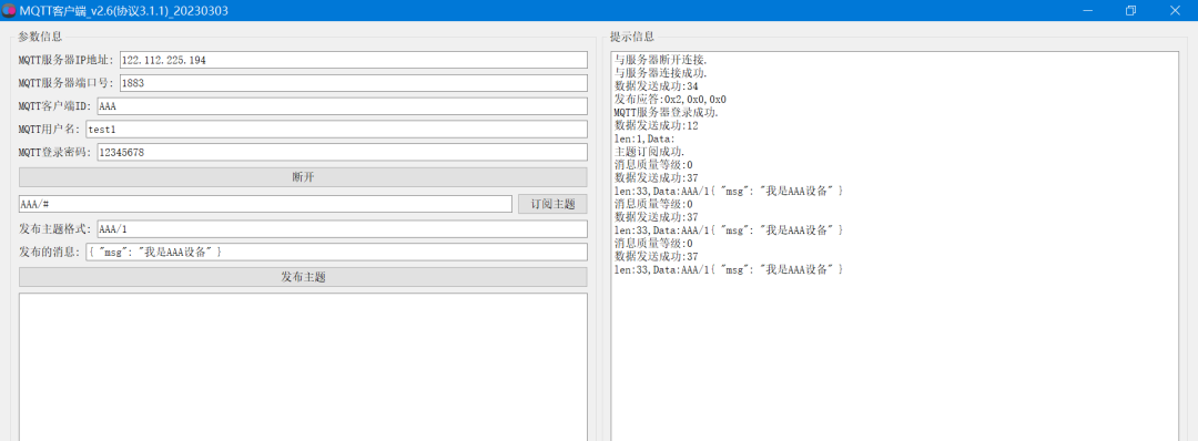
Note: Currently, client authentication has not been configured. As long as the IP and port are entered correctly, any MQTT trio can log in to the server; the server does not perform validation on the trio.
EMQX’s default configuration enables anonymous authentication, allowing any client to connect to EMQX. When no authentication plugin is enabled, or the authentication plugin does not explicitly allow/deny (ignore) connection requests, EMQX will decide whether to allow client connections based on the status of anonymous authentication.
Then open the EMQX management backend, and you can see that our device has logged into the server, named test1.
In the topic subscription page, you can also see the topics that our client device is subscribed to.
5.5 Client Authentication Configuration
EMQX’s default configuration enables anonymous authentication, allowing any client to connect to EMQX. When no authentication plugin is enabled, or the authentication plugin does not explicitly allow/deny (ignore) connection requests, EMQX will decide whether to allow client connections based on the status of anonymous authentication.
In formal products, authentication must be enabled; otherwise, any device can connect.
Below is how to configure client authentication.
[1] Open the client authentication page
[2] Select password authentication
[3] Select built-in database
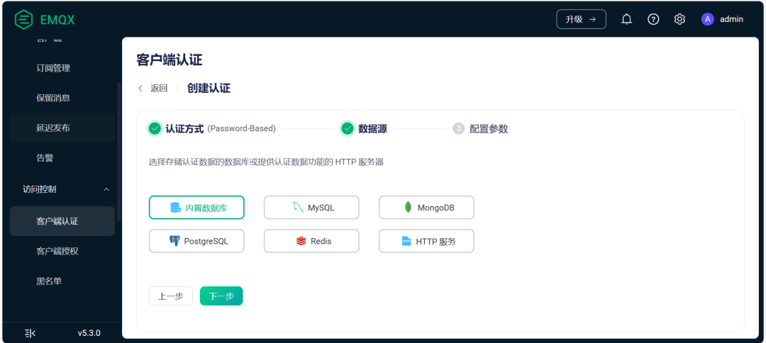
[4] Set the authentication method (can be default, no need to change), and click create directly.
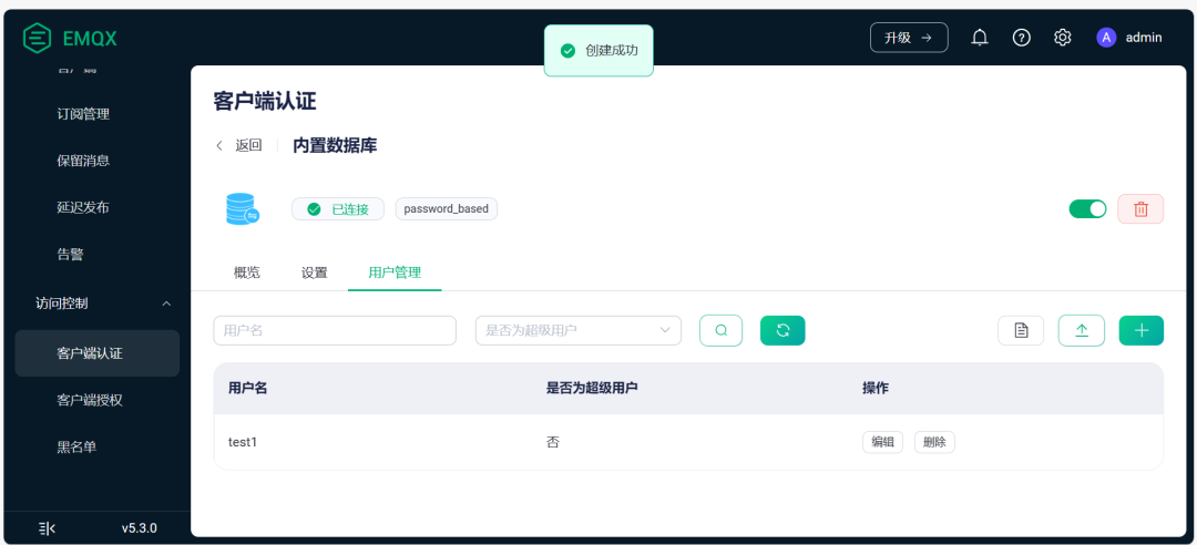
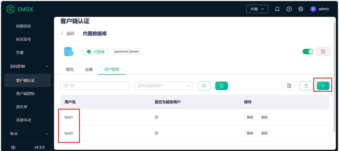
[5] After successful creation, click on user management
[6] Add user
[7] Successfully added
[8] After adding, open the MQTT client for testing.
When logging in, the MQTT username and password must be filled in correctly according to the information added in the previous step; otherwise, you will not be able to log into the server.
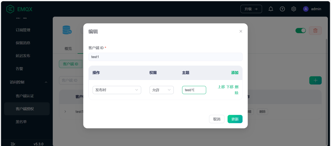
5.6 Client Authorization Configuration
The client authorization page can configure the publishing and subscription permissions for each client (device). It restricts whether it can publish topics and subscribe to topics. If needed, you can configure it.
http://127.0.0.1:18083/#/authorization/detail/built_in_database?tab=users
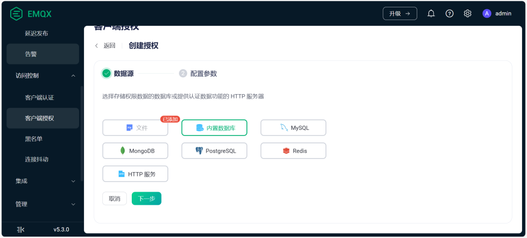
[1] Create data source
[2] Select built-in database
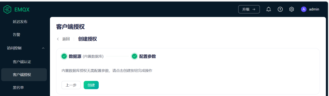
[3] Complete creation
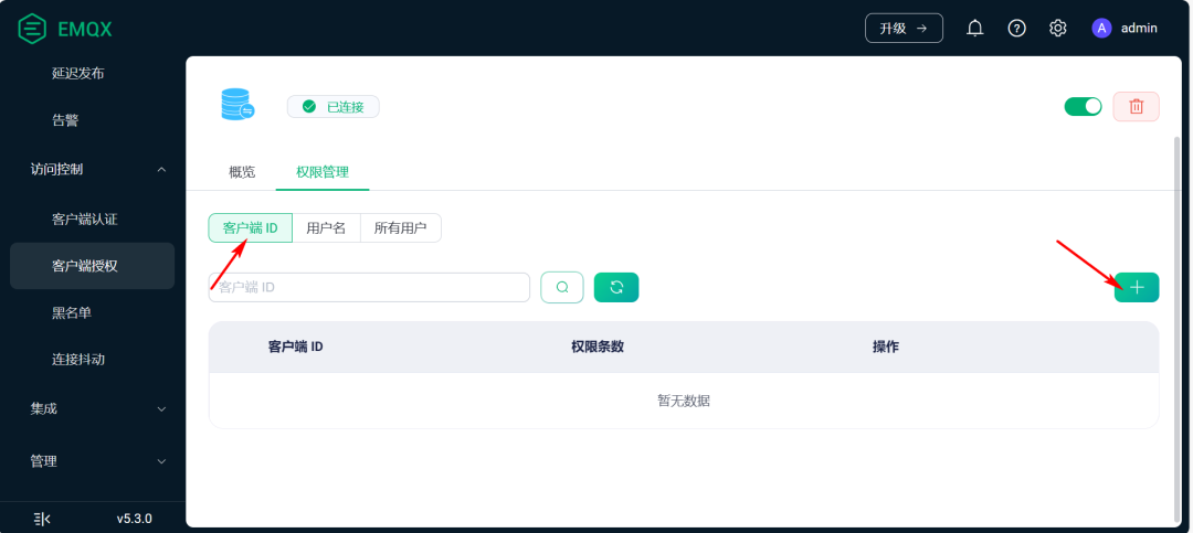
[4] Click on permission management
[5] Select client ID and click add
[6] Configure permissions
5.7 Data Forwarding (Integration)
In the integration options, device data processing can be performed. For example, forwarding to your own HTTP server, forwarding to other MQTT servers, creating rules, and triggering certain actions based on certain events, etc.
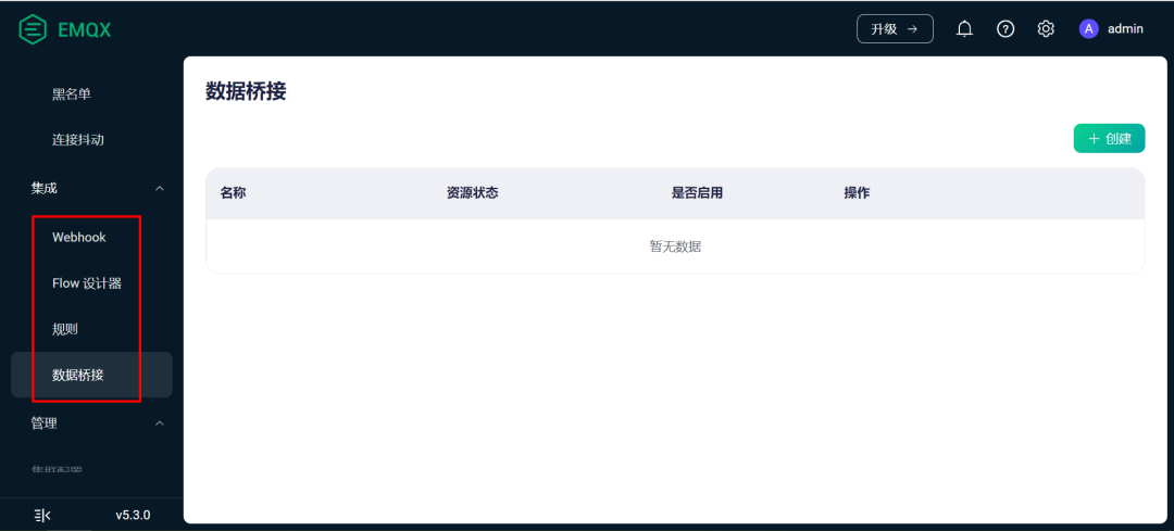
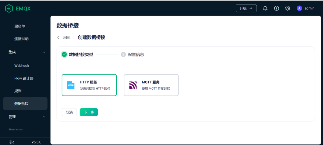
Select data bridging.
You can send data to your own HTTP server or to other MQTT servers.
7. MQTT Client Message Mutual Test
7.1 Add 2 Devices
To facilitate testing the mutual subscription of topics and data transmission between devices, at least 2 devices should be added on the client authentication page. Here, I added test1 and test2.
7.2 Device Testing
Device A subscribes to Device B’s topic, and Device B subscribes to Device A’s topic, achieving mutual data transmission.
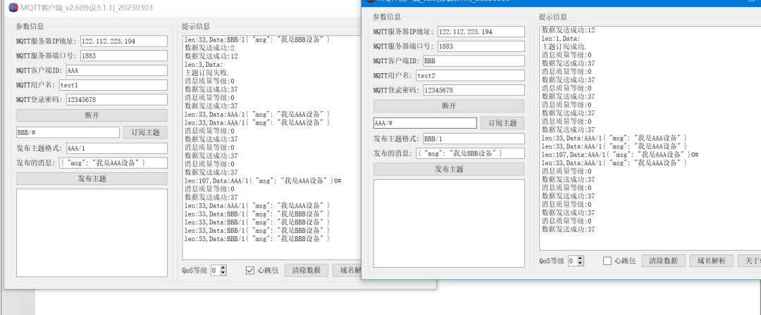
Device A’s MQTT Information:
cpp
MQTT Server Address: 122.112.225.194
MQTT Server Port: 1883
MQTT Client ID: AAA
MQTT Username: test1
MQTT Login Password: 12345678

Subscription Topic: BBB/#
Publish Topic: AAA/1
Published Message: { "msg": "I am device AAA" }
Device B’s MQTT Information:
cpp
MQTT Server Address: 122.112.225.194
MQTT Server Port: 1883
MQTT Client ID: BBB
MQTT Username: test2
MQTT Login Password: 12345678

Subscription Topic: AAA/#
Publish Topic: BBB/1
Published Message: { "msg": "I am device BBB" }
8. STM32 Hardware Development
8.1 AT Command Debugging Process of BC26 Module
AT command sending process for BC20/BC26 to enable GPS and connect to MQTT server.
(1) Check if the module is functioning normally
cpp
AT

OK
(2) Get the card number, check if the card is inserted properly
cpp
AT+CIMI

460041052911195

OK
(3) Activate the network
cpp
AT+CGATT=1

OK
(4) Check network activation status
cpp
AT+CGATT?

+CGATT: 1

OK
(5) Check network quality
cpp
AT+CSQ

+CSQ: 26,0

OK
(6) Check network status
cpp
AT+CEREG=? // Check network status
+CEREG: 0,1 // Network found successfully
OK
(7) Activate GPS
cpp
Activate GPS, wait for a while
AT+QGNSSC=1

OK
(8) Check GPS activation status
cpp
Check activation status, 1 indicates successful activation
AT+QGNSSC?

+QGNSSC: 1

OK
(9) Get a GPS location statement
cpp
AT+QGNSSRD="NMEA/RMC"
+QGNSSRD: $GNRMC,120715.00,A,3150.78179,N,11711.93433,E,0.000,,310818,,,A,V*19

OK
(10) Connect to the MQTT server
cpp
AT+QMTOPEN=0,"a161a58a78.iot-mqtts.cn-north-4.myhuaweicloud.com",1883

OK

+QMTOPEN: 0,0
(11) Log in to the MQTT server
cpp
Command format: AT+QMTCONN=<tcpconnectid>,<clientid>,<username>,<password>
AT+QMTCONN=0,"6210e8acde9933029be8facf_dev1_0_0_2022021913","6210e8acde9933029be8facf_dev1","6cea55404b463e666cd7a6060daba745bbaa17fe7078dfef45f8151cdf19673d"

OK

+QMTCONN: 0,0,0
</password></username></clientid></tcpconnectid>
(12) Subscribe to a topic
cpp
Command format: AT+QMTSUB=<tcpconnectid>,<msgid>,"<topic1>",<qos1>[,"<topic2>",<qos2>...]

AT+QMTSUB=0,1,"$oc/devices/6210e8acde9933029be8facf_dev1/sys/messages/down",2

OK

+QMTSUB: 0,1,0,2
</qos2></topic2></qos1></topic1></msgid></tcpconnectid>
(13) Publish a topic
cpp
Command format:AT+QMTPUB=<tcpconnectid>,<msgid>,<qos>,<retain>,"<topic>","<msg>"

First send the command:
AT+QMTPUB=0,0,0,0,"$oc/devices/6210e8acde9933029be8facf_dev1/sys/properties/repor"

Wait for the return ">"
Then send the data. No need to add a carriage return.
{"services": [{"service_id": "gps","properties":{"longitude":12.345,"latitude":33.345}}]}
Data sending completed, then send the end character. The hexadecimal value --0x1a. Some serial port debugging assistants can adapt to ctrl+z shortcut key input 0xA
Wait for the module to return "OK", and the data sending is completed.

OK

+QMTPUB: 0,0,0
</msg></topic></retain></qos></msgid></tcpconnectid>
8.2 BH1750 Sensor
The following is the code for communicating with the BH1750 light sensor through the I2C interface, reading the light-sensitive value, and printing it via the serial port:
cpp
#include "stm32f1xx_hal.h"
#include "stdio.h"

I2C_HandleTypeDef hi2c1;
UART_HandleTypeDef huart1;

#define BH1750_ADDRESS (0x23 << 1) // BH1750 address

void SystemClock_Config(void);
static void MX_GPIO_Init(void);
static void MX_USART1_UART_Init(void);
static void MX_I2C1_Init(void);

int main(void)
{
    HAL_Init();
    SystemClock_Config();
    MX_GPIO_Init();
    MX_USART1_UART_Init();
    MX_I2C1_Init();

    uint8_t data[2];
    uint16_t lux;

    while (1)
    {
        HAL_I2C_Master_Transmit(&hi2c1, BH1750_ADDRESS, (uint8_t[]){0x10}, 1, HAL_MAX_DELAY); // Set single high-resolution mode
        HAL_Delay(180); // Wait for the sensor to complete measurement

        HAL_I2C_Master_Receive(&hi2c1, BH1750_ADDRESS, data, 2, HAL_MAX_DELAY); // Read light value
        lux = (data[0] << 8) | data[1];

        char buffer[20];
        sprintf(buffer, "Lux: %d\r\n", lux);
        HAL_UART_Transmit(&huart1, (uint8_t *)buffer, strlen(buffer), HAL_MAX_DELAY); // Print light value via serial port

        HAL_Delay(1000); // Delay 1 second
    }
}

void SystemClock_Config(void)
{
    RCC_OscInitTypeDef RCC_OscInitStruct = {0};
    RCC_ClkInitTypeDef RCC_ClkInitStruct = {0};

    RCC_OscInitStruct.OscillatorType = RCC_OSCILLATORTYPE_HSE;
    RCC_OscInitStruct.HSEState = RCC_HSE_ON;
    RCC_OscInitStruct.HSEPredivValue = RCC_HSE_PREDIV_DIV1;
    RCC_OscInitStruct.PLL.PLLState = RCC_PLL_ON;
    RCC_OscInitStruct.PLL.PLLSource = RCC_PLLSOURCE_HSE;
    RCC_OscInitStruct.PLL.PLLMUL = RCC_PLL_MUL9;
    if (HAL_RCC_OscConfig(&RCC_OscInitStruct) != HAL_OK)
    {
        Error_Handler();
    }

    RCC_ClkInitStruct.ClockType = RCC_CLOCKTYPE_HCLK | RCC_CLOCKTYPE_SYSCLK | RCC_CLOCKTYPE_PCLK1 | RCC_CLOCKTYPE_PCLK2;
    RCC_ClkInitStruct.SYSCLKSource = RCC_SYSCLKSOURCE_PLLCLK;
    RCC_ClkInitStruct.AHBCLKDivider = RCC_SYSCLK_DIV1;
    RCC_ClkInitStruct.APB1CLKDivider = RCC_HCLK_DIV2;
    RCC_ClkInitStruct.APB2CLKDivider = RCC_HCLK_DIV1;
    if (HAL_RCC_ClockConfig(&RCC_ClkInitStruct, FLASH_LATENCY_2) != HAL_OK)
    {
        Error_Handler();
    }
}

static void MX_I2C1_Init(void)
{
    hi2c1.Instance = I2C1;
    hi2c1.Init.ClockSpeed = 400000;
    hi2c1.Init.DutyCycle = I2C_DUTYCYCLE_2;
    hi2c1.Init.OwnAddress1 = 0;
    hi2c1.Init.AddressingMode = I2C_ADDRESSINGMODE_7BIT;
    hi2c1.Init.DualAddressMode = I2C_DUALADDRESS_DISABLE;
    hi2c1.Init.OwnAddress2 = 0;
    hi2c1.Init.GeneralCallMode = I2C_GENERALCALL_DISABLE;
    hi2c1.Init.NoStretchMode = I2C_NOSTRETCH_DISABLE;
    if (HAL_I2C_Init(&hi2c1) != HAL_OK)
    {
        Error_Handler();
    }
}

static void MX_USART1_UART_Init(void)
{
    huart1.Instance = USART1;
    huart1.Init.BaudRate = 115200;
    huart1.Init.WordLength = UART_WORDLENGTH_8B;
    huart1.Init.StopBits = UART_STOPBITS_1;
    huart1.Init.Parity = UART_PARITY_NONE;
    huart1.Init.Mode = UART_MODE_TX_RX;
    huart1.Init.HwFlowCtl = UART_HWCONTROL_NONE;
    huart1.Init.OverSampling = UART_OVERSAMPLING_16;
    if (HAL_UART_Init(&huart1) != HAL_OK)
    {
        Error_Handler();
    }
}

void Error_Handler(void)
{
    while (1)
    {
    }
}

#ifdef USE_FULL_ASSERT
void assert_failed(uint8_t *file, uint32_t line)
{
}
#endif
8.3 DHT11 Temperature and Humidity Module
The following is the code for reading environmental temperature and humidity data from the DHT11 temperature and humidity sensor and printing it via the serial port:
cpp
#include "stm32f1xx_hal.h"
#include "stdio.h"

TIM_HandleTypeDef htim2;
UART_HandleTypeDef huart1;

#define DHT11_GPIO_PORT GPIOA
#define DHT11_GPIO_PIN GPIO_PIN_0

void SystemClock_Config(void);
static void MX_GPIO_Init(void);
static void MX_USART1_UART_Init(void);
static void MX_TIM2_Init(void);

int main(void)
{
    HAL_Init();
    SystemClock_Config();
    MX_GPIO_Init();
    MX_USART1_UART_Init();
    MX_TIM2_Init();

    HAL_TIM_Base_Start(&htim2);

    while (1)
    {
        HAL_TIM_Base_Start(&htim2);
        HAL_Delay(2000); // Wait for 2 seconds

        // Send start signal
        HAL_GPIO_WritePin(DHT11_GPIO_PORT, DHT11_GPIO_PIN, GPIO_PIN_RESET);
        HAL_Delay(18);
        HAL_GPIO_WritePin(DHT11_GPIO_PORT, DHT11_GPIO_PIN, GPIO_PIN_SET);
        HAL_Delay(20);

        // Set pin as input
        GPIO_InitTypeDef GPIO_InitStruct = {0};
        GPIO_InitStruct.Pin = DHT11_GPIO_PIN;
        GPIO_InitStruct.Mode = GPIO_MODE_INPUT;
        GPIO_InitStruct.Pull = GPIO_PULLUP;
        HAL_GPIO_Init(DHT11_GPIO_PORT, &GPIO_InitStruct);

        // Wait for DHT11 response
        while (!HAL_GPIO_ReadPin(DHT11_GPIO_PORT, DHT11_GPIO_PIN))
            ;
        while (HAL_GPIO_ReadPin(DHT11_GPIO_PORT, DHT11_GPIO_PIN))
            ;

        // Read data
        uint8_t data[5] = {0};
        for (int i = 0; i < 5; i++)
        {
            for (int j = 0; j < 8; j++)
            {
                while (!HAL_GPIO_ReadPin(DHT11_GPIO_PORT, DHT11_GPIO_PIN))
                    ;
                HAL_TIM_Base_Start(&htim2);
                while (HAL_GPIO_ReadPin(DHT11_GPIO_PORT, DHT11_GPIO_PIN))
                    ;
                if (HAL_TIM_Base_GetCounter(&htim2) > 40)
                    data[i] |= (1 << (7 - j));
            }
        }

        // Calculate temperature and humidity
        uint8_t humidity = data[0];
        uint8_t temperature = data[2];

        char buffer[50];
        sprintf(buffer, "Temperature: %d°C, Humidity: %d%%\r\n", temperature, humidity);
        HAL_UART_Transmit(&huart1, (uint8_t *)buffer, strlen(buffer), HAL_MAX_DELAY); // Print temperature and humidity data via serial port
    }
}

void SystemClock_Config(void)
{
    RCC_OscInitTypeDef RCC_OscInitStruct = {0};
    RCC_ClkInitTypeDef RCC_ClkInitStruct = {0};

    RCC_OscInitStruct.OscillatorType = RCC_OSCILLATORTYPE_HSE;
    RCC_OscInitStruct.HSEState = RCC_HSE_ON;
    RCC_OscInitStruct.HSEPredivValue = RCC_HSE_PREDIV_DIV1;
    RCC_OscInitStruct.PLL.PLLState = RCC_PLL_ON;
    RCC_OscInitStruct.PLL.PLLSource = RCC_PLLSOURCE_HSE;
    RCC_OscInitStruct.PLL.PLLMUL = RCC_PLL_MUL9;
    if (HAL_RCC_OscConfig(&RCC_OscInitStruct) != HAL_OK)
    {
        Error_Handler();
    }

    RCC_ClkInitStruct.ClockType = RCC_CLOCKTYPE_HCLK | RCC_CLOCKTYPE_SYSCLK | RCC_CLOCKTYPE_PCLK1 | RCC_CLOCKTYPE_PCLK2;
    RCC_ClkInitStruct.SYSCLKSource = RCC_SYSCLKSOURCE_PLLCLK;
    RCC_ClkInitStruct.AHBCLKDivider = RCC_SYSCLK_DIV1;
    RCC_ClkInitStruct.APB1CLKDivider = RCC_HCLK_DIV2;
    RCC_ClkInitStruct.APB2CLKDivider = RCC_HCLK_DIV1;
    if (HAL_RCC_ClockConfig(&RCC_ClkInitStruct, FLASH_LATENCY_2) != HAL_OK)
    {
        Error_Handler();
    }
}

static void MX_TIM2_Init(void)
{
    htim2.Instance = TIM2;
    htim2.Init.Prescaler = 72 - 1;
    htim2.Init.CounterMode = TIM_COUNTERMODE_UP;
    htim2.Init.Period = 65535;
    htim2.Init.ClockDivision = TIM_CLOCKDIVISION_DIV1;
    HAL_TIM_Base_Init(&htim2);
}

static void MX_USART1_UART_Init(void)
{
    huart1.Instance = USART1;
    huart1.Init.BaudRate = 115200;
    huart1.Init.WordLength = UART_WORDLENGTH_8B;
    huart1.Init.StopBits = UART_STOPBITS_1;
    huart1.Init.Parity = UART_PARITY_NONE;
    huart1.Init.Mode = UART_MODE_TX_RX;
    huart1.Init.HwFlowCtl = UART_HWCONTROL_NONE;
    huart1.Init.OverSampling = UART_OVERSAMPLING_16;
    if (HAL_UART_Init(&huart1) != HAL_OK)
    {
        Error_Handler();
    }
}

void Error_Handler(void)
{
    while (1)
    {
    }
}

#ifdef USE_FULL_ASSERT
void assert_failed(uint8_t *file, uint32_t line)
{
}
#endif
8.4 Soil Moisture Sensor
The code for reading soil moisture through the ADC module and printing it via the serial port is as follows:
cpp
#include "stm32f1xx_hal.h"
#include "stdio.h"

ADC_HandleTypeDef hadc1;
UART_HandleTypeDef huart1;

void SystemClock_Config(void);
static void MX_GPIO_Init(void);
static void MX_USART1_UART_Init(void);
static void MX_ADC1_Init(void);

int main(void)
{
    HAL_Init();
    SystemClock_Config();
    MX_GPIO_Init();
    MX_USART1_UART_Init();
    MX_ADC1_Init();

    uint16_t adc_value;

    while (1)
    {
        HAL_ADC_Start(&hadc1); // Start ADC conversion
        if (HAL_ADC_PollForConversion(&hadc1, 100) == HAL_OK)
        {
            adc_value = HAL_ADC_GetValue(&hadc1); // Read ADC value
            char buffer[50];
            sprintf(buffer, "Soil Moisture: %d\r\n", adc_value);
            HAL_UART_Transmit(&huart1, (uint8_t *)buffer, strlen(buffer), HAL_MAX_DELAY); // Print soil moisture data via serial port
        }
        HAL_Delay(1000); // Delay 1 second
    }
}

void SystemClock_Config(void)
{
    // Omitted, configure system clock according to actual situation
}

static void MX_ADC1_Init(void)
{
    ADC_ChannelConfTypeDef sConfig = {0};

    hadc1.Instance = ADC1;
    hadc1.Init.ScanConvMode = DISABLE;
    hadc1.Init.ContinuousConvMode = DISABLE;
    hadc1.Init.DiscontinuousConvMode = DISABLE;
    hadc1.Init.ExternalTrigConv = ADC_SOFTWARE_START;
    hadc1.Init.DataAlign = ADC_DATAALIGN_RIGHT;
    hadc1.Init.NbrOfConversion = 1;
    if (HAL_ADC_Init(&hadc1) != HAL_OK)
    {
        Error_Handler();
    }

    sConfig.Channel = ADC_CHANNEL_0; // Change to the actual connected channel
    sConfig.Rank = 1;
    sConfig.SamplingTime = ADC_SAMPLETIME_13CYCLES_5; // Adjust sampling time according to actual situation
    if (HAL_ADC_ConfigChannel(&hadc1, &sConfig) != HAL_OK)
    {
        Error_Handler();
    }
}

static void MX_USART1_UART_Init(void)
{
    huart1.Instance = USART1;
    huart1.Init.BaudRate = 115200;
    huart1.Init.WordLength = UART_WORDLENGTH_8B;
    huart1.Init.StopBits = UART_STOPBITS_1;
    huart1.Init.Parity = UART_PARITY_NONE;
    huart1.Init.Mode = UART_MODE_TX_RX;
    huart1.Init.HwFlowCtl = UART_HWCONTROL_NONE;
    huart1.Init.OverSampling = UART_OVERSAMPLING_16;
    if (HAL_UART_Init(&huart1) != HAL_OK)
    {
        Error_Handler();
    }
}

void Error_Handler(void)
{
    while (1)
    {
    }
}

#ifdef USE_FULL_ASSERT
void assert_failed(uint8_t *file, uint32_t line)
{
}
#endif
9. Conclusion
This smart agriculture management system design and implementation project is based on the STM32F103RCT6 microcontroller as the core, integrating DHT11 temperature and humidity sensor, BH1750 light intensity sensor, and soil moisture detection sensor to construct a comprehensive farmland environment monitoring system. When environmental parameters exceed preset thresholds, the system can issue real-time alarms and automatically remind or alert for irrigation, fertilization, and other operations while emitting sound alarms through the buzzer.
In terms of remote control, the system uses the NBIoT-BC26 module to achieve wireless communication functions, transmitting the collected data to the cloud MQTT server, and processing the data through the server built on the EMQX open-source framework. Users can view various real-time data of the farmland environment anytime and anywhere through the WeChat mini-program, achieving remote monitoring of the growing environment of crops and conveniently executing manual irrigation, turning on supplementary lights, and other remote control operations.
The successful implementation of this project not only effectively improves the intelligence level in the agricultural production process and reduces labor management costs but also provides strong technical support for achieving precision agriculture and smart agriculture. In the future, with the further development of IoT technology, cloud computing, and artificial intelligence technology, this smart agriculture management system is expected to be promoted in more fields, helping modern agriculture in China move towards a more efficient, intelligent, and sustainable direction.