
In the previous article: AI System – 22 Introduction to AI Chip Storage, various storage types were discussed, but when the Core accesses data, it often encounters data consistency issues, which have already been successfully identified as common sources of errors in software, especially the inconsistencies seen between heterogeneous cores and multi-core data inconsistencies, leading to business logic errors, and can even directly cause the OS to crash.
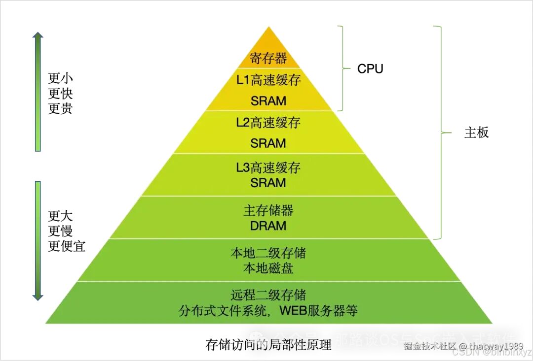 As shown in the figure above, information is retrieved from the CPU in a hierarchical manner, with increasing speed at each level. Among these levels, there are many caches, which present consistency issues. In the AI System – 23 Introduction to AI Chip CPU Subsystem, many efforts were made to ensure data consistency in the CPU subsystem. However, there are also consistency issues during communication, such as in the AI System – 21 AI Chip NoC Bus.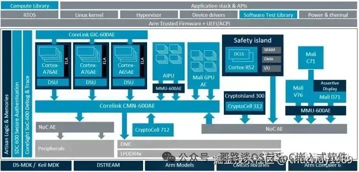
1. Multi-core Cache Consistency
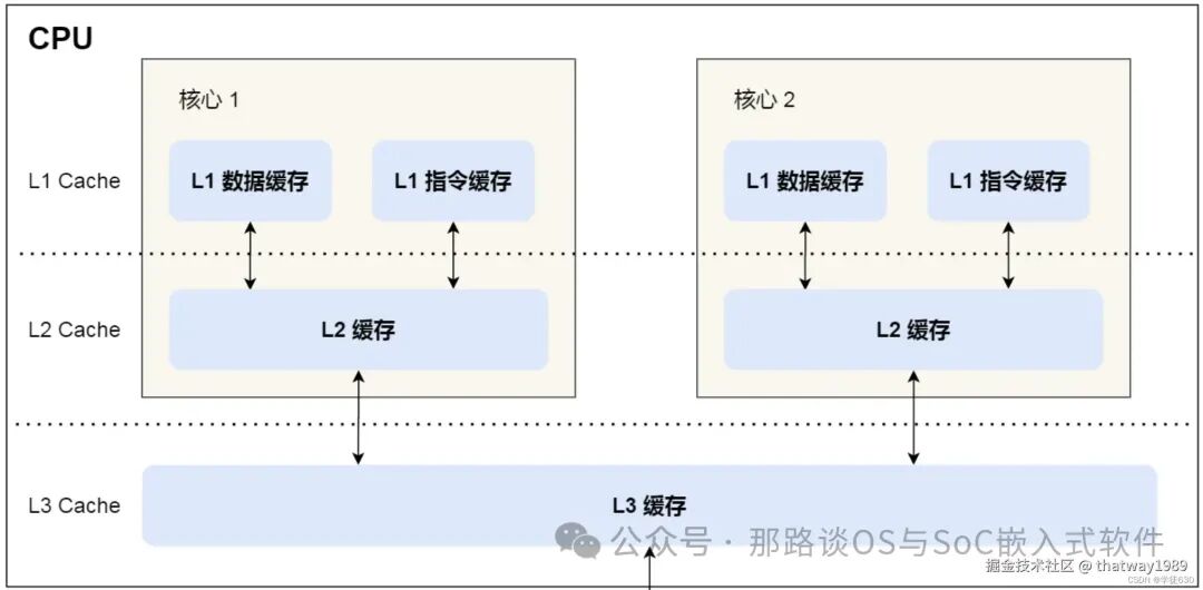
To enhance the CPU’s computational power, one approach is to increase the CPU frequency, while the other is to optimize the bottleneck during the data exchange between DDR and CPU, which takes time. This requires adding a cache between the CPU and DDR to reduce the CPU’s blind wait time.
CPU Cache is typically divided into three levels: L1 Cache, L2 Cache, L3 Cache, where the lower the level, the closer it is to the CPU core, and the access speed is faster, but the storage capacity is relatively smaller. In multi-core CPUs, each core has its own L1/L2 Cache, while L3 Cache is shared among all cores.
1.1 Why Cache Inconsistency Occurs
Why does cache inconsistency occur?
Data not only involves read operations but also write operations. If data is written to the Cache, the corresponding data in memory and Cache will differ, leading to inconsistency between Cache and memory data, thus we must synchronize the data in Cache to memory.
How to resolve cache inconsistency between two cores? Below are several logical approaches:
- Write-through
- Write-back on cache replacement
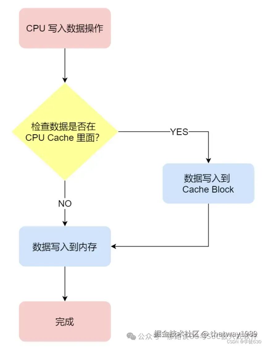
Write-through: When writing data, both the cache and memory are updated simultaneously. This works but is inefficient.
Write-back on cache replacement:
-
If a write operation occurs and the data is already in the CPU Cache, update the data in the CPU Cache and mark this Cache Block as dirty. This dirty mark indicates that the data in the CPU Cache is inconsistent with memory, and there is no need to write the data back to memory;
-
If a write operation occurs and the data is not in the CPU Cache, check if the data in this Cache Block is marked as dirty:
a. If it is dirty, write the data in this Cache Block back to memory, then read the current data to be written from memory into the Cache Block, and finally write the current data into the Cache Block, marking it as dirty;
b. If it is not dirty, read the current data to be written from memory into the Cache Block, then write the current data into this Cache Block, and mark this Cache Block as dirty.
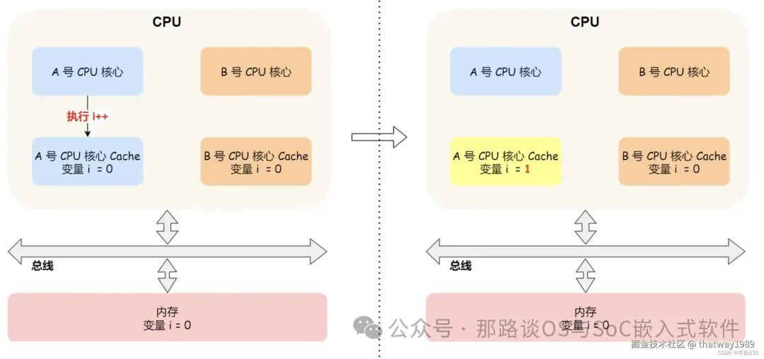
Write-back on cache replacement has its issues,
- Data will only be written back to memory when the Cache Block in Core A is replaced.
- If Core B attempts to read the value of variable i from memory at this time, it will read an incorrect value because Core A has updated the value of i but has not yet written it back to memory, leaving the memory value still at 0. This is the so-called cache consistency issue, where the caches of Core A and Core B are inconsistent at this moment, leading to erroneous execution results.
1.2 How to Solve Multi-core Cache Inconsistency
To solve this issue, a mechanism is needed to synchronize the cache data between two different cores. This mechanism must ensure the following two points:
- When the Cache data in a certain CPU core is updated, it must propagate to the Cache of other cores, which is called write propagation;
- The operation order of data in a certain CPU core must appear to be the same in other cores, which is called transaction serialization. In simple terms, modifications to the data must be FIFO in each core, meaning later modifications cannot occur before earlier ones.
Thus, the bus snooping method was developed: when Core A modifies the value of variable i in L1 Cache, this event is broadcasted to notify all other cores. Each CPU core listens to the broadcast events on the bus and checks if it has the same data in its L1 Cache. If Core B has this data in its L1 Cache, it also needs to update this data in its L1 Cache. This bus is called: coherent bus (Coherent Bus), and the operations that notify related caches during cache consistency maintenance are called snoops.
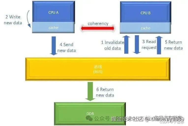
Issues:
-
The CPU must constantly listen to all activities on the bus, regardless of whether other cores’ caches contain the same data, and must broadcast events, which will increase the bus load.
-
Bus snooping only ensures that the event of a CPU core’s Cache updating data is known to other CPU cores, but it does not guarantee transaction serialization.
A protocol based on the bus snooping mechanism implements transaction serialization and uses a state machine mechanism to reduce bus bandwidth pressure. This protocol is the MESI protocol, which achieves CPU cache consistency.
The MESI protocol is actually an acronym for the first letters of four state words:

Advantages of the MESI protocol:
- It can detect when the Cache Line state is “Modified” or “Exclusive”, allowing updates to its data without sending broadcasts to other CPU cores, thus reducing bus bandwidth pressure to some extent.
- When a processor wants to read or modify a cache line, the MESI protocol coordinates based on the current state of the cache line and the states of other processors’ cache lines. For example, if a processor wants to modify a cache line that is in the Shared state, the protocol first sets the state of that cache line to Modified and invalidates the cache lines of other processors, ensuring that the cache line can only be accessed by the current processor, thus achieving serialized execution of transactions.
1.3 CHI Protocol
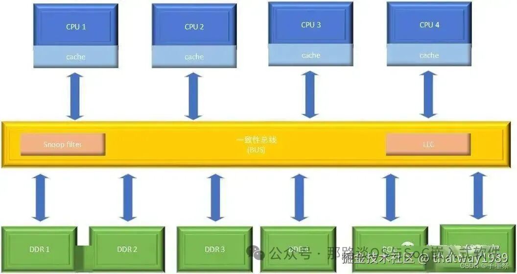
The coherent bus uses snoop filters to record the cache line states in each cache, keeping track of the state of each cache line from the bus’s perspective. Common cache consistency protocols include two types: MESI and MOESI.
The inconvenience of the MESI protocol is that if CPU A has a cache line in the M state and CPU B wants to access this cache line, the bus must notify CPU A to synchronize the cache line to the main memory. During this process, the interaction between the bus and the main memory can take a long time. If CPU A’s data can be sent to CPU B over the bus without synchronizing back to the main memory, it would save time and improve efficiency.
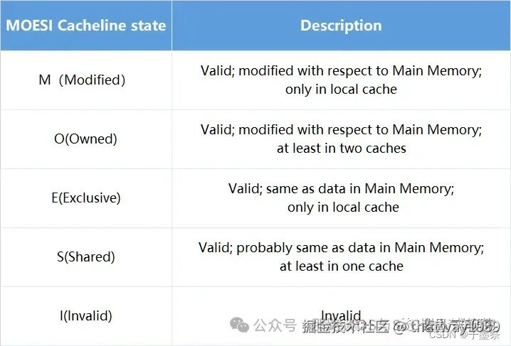
The MOESI protocol optimizes this inconvenience.MOESI protocol allows sharing of dirty cache lines between caches. Dirty means that the cache line has changed relative to the main memory, allowing for time savings in interactions with the main memory, as the cache line can be transferred between caches without needing to write back to the main memory.
Compared to MESI, MOESI has an additional O state, which indicates that the cache line differs from the value in the main memory, exists in at least two caches, and is refreshed to the main memory by the cache when needed. Additionally, the S state of MESI differs from that of MOESI; in MESI, the cache line in the S state is consistent with the main memory, while in MOESI, the cache line in the S state may not be consistent with the main memory, as it may share a dirty cache line but is not obligated to refresh the cache line to the main memory.
Currently, the CHI protocol is commonly used to implement communication between various components on the coherent bus. This protocol uses MOESI to manage the corresponding cache line states. CHI is flexible for designing chip systems based on coherent buses, supporting the construction of small, medium, or large chip systems. The system includes multiple components, from CPU, GPU, DDR to peripheral interfaces, as well as the interconnect itself.
To improve the CPU’s data access rate, a Last Level Cache (LLC) is usually added to the coherent bus. LLC is a dedicated cache, which is a level of cache below the CPU cache, used to cache cache lines that pass through the bus, increasing the total cache capacity on the chip. When the bus cannot obtain the required data from the CPU’s cache, it can first check if the LLC contains the corresponding data. If it hits, it can provide data to the CPU without accessing the main memory or peripherals. This multi-level cache structure effectively reduces the number of times the chip accesses the main memory or peripherals, providing the necessary data transport capability for high-performance CPUs.
CHI protocol stands for Coherent Hub Interface. The CHI protocol is the fifth generation of AMBA protocols and can be considered an evolution of the ACE protocol, completing all information transmission in packet form. However, from the interface perspective, CHI is completely different from ACE, AXI, and other protocols.
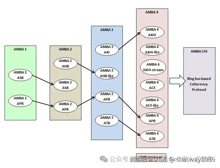
The evolution of the AMBA CHI protocol is as follows:
-
AMBA 1 only had ASB and APB protocols;
-
AMBA 2 introduced the AHB protocol for high-speed data transmission;
-
AMBA 3 adapted to high throughput transmission and debugging by introducing AXI and ATB, while the AHB protocol was reduced to AHB-lite, and the APB protocol added PREADY and PSLVERR, while ASB was no longer used due to design complexity;
-
AMBA 4 enhanced AXI, introduced support for QoS and long bursts, allowing for AXI4, AXI4-lite, AXI4-stream based on different applications, while introducing ACE and ACE-lite protocols for maintaining operational consistency in complex SoCs, and enhancing APB and ATB, such as adding PPROT and PSTRB to APB, and introducing the QVN protocol to improve bus data transmission;
-
Recently, to adapt to more complex high-speed NoC designs, the ring bus protocol was introduced, leading to the release of the AMBA CHI protocol.
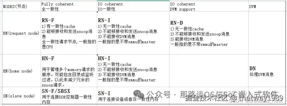
There are mainly three types of nodes: Request Node (RN), Home Node (HN), and Slave Node (SN). Additionally, there are Miscellaneous Nodes (MN).
RN generates transactions, such as read and write requests, which are sent to HN. HN is responsible for ordering requests, generating transactions to SN, and can issue snoop or DVM operations.
These node types can be further divided into the following categories:
RN nodes can be fully coherent, I/O coherent, or I/O coherent with DVM support:
- Fully coherent request node (RN-F), contains coherent caches and will accept and respond to snoops;
- I/O coherent request node (RN-I), does not have coherent caches and cannot accept snoops;
- I/O coherent request node with DVM support (RN-D), has the same functionality as RN-I but can also accept DVM messages;
Home nodes can be fully coherent, non-coherent, or miscellaneous:
- Fully coherent home node (HN-F) orders all requests for coherent memory and issues snoops to RN-F;
- Non-coherent home node (HN-I) orders requests for the I/O subsystem;
- Miscellaneous nodes (MN) handle DVM transactions sent from request nodes. These are sometimes implemented as HN-D nodes.
Slave nodes (SN-F) are suitable for normal memory or peripherals and normal memory:
- SN-F connects to memory devices that support coherent memory space. For example, a memory controller will connect to an SN-F node.
- SN-F connects to I/O peripherals or non-coherent memory for peripherals or normal memory.
Reference: https://blog.csdn.net/dajiao_zi/article/details/138194334
1.4 DSU
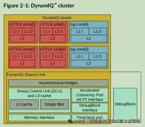
First, introduce the cache consistency IP between some cores in clusters: DSU, which also provides L3 cache by cluster. This was introduced in the previous article AI System – 23 Introduction to AI Chip CPU Subsystem in section 2.2.
- Cluster binding usage: The core function is to control the CPU cores to use them in clusters, where each core in the cluster can be individually turned on/off, and frequency/voltage can be adjusted, achieving better energy efficiency. Manufacturers can even place different cores in a cluster in an unequal number, balancing cost and performance.
- L3 cache sharing: DSU can use different bus technologies like CCI, CCN, or CMN to connect the CPU to other units in the SoC (GPU, Modem, memory) at high speed; if it has 4MB of L3 cache, it can dynamically allocate cache to each core. For example, in Cortex-A75×1 + Cortex-A55×7, it can allocate 3MB of cache to the A75 core, while the remaining 7 A55 cores share 1MB of cache, and it can even allocate the L3 cache to other units like the GPU, providing high flexibility;
- Redundant design: When designing DynamIQ, ARM also considered redundancy requirements. For example, compared to smartphones, cars have much higher reliability and redundancy requirements. DynamIQ allows multiple clusters to be connected via CCIX, so processors can be distributed in different locations in the car. When an accident occurs and one cluster is damaged, DynamIQ technology can call upon backup processors to ensure the car operates normally.
The DynamIQ™ Shared Unit (DSU) includes L3 memory system, control logic, and external interfaces to support DynamIQ™ clusters. The microarchitecture of DynamIQ™ clusters integrates one or more cores with the DSU, forming a cluster implemented according to a specified configuration. During the implementation of macro units, cores can be selected and configured.
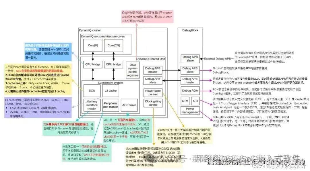
It can be seen that it also uses ACE or CHI protocols, including the MOESI mechanism. The Snoop Control Unit (SCU) in the DSU maintains consistency between the processing cores and the L3 cache. This ensures that all cores have a synchronized and consistent view of shared data, preventing data inconsistency issues.
Snoop Control Unit (SCU) is a key component in multi-processor systems, especially in designs involving cache consistency, such as symmetric multiprocessor clusters (SMP) or systems on chip (SoC). Its main role is to maintain cache consistency, ensuring that all processor cores have a unified view of the contents of shared caches, thus guaranteeing data consistency and correctness. The working mechanism of the SCU typically includes the following aspects:
- Snooping: The SCU listens to all access requests from processor cores to shared caches, including read and write operations. When a core attempts to modify data in the cache, the SCU intervenes to ensure that other cores’ cached copies of that data do not become stale.
- Cache updates: If the data requested by one core is dirty (modified but not written back to main memory) in another core’s cache, the SCU prompts the core holding that dirty data to write it back to the shared cache or main memory, then updates the requesting core’s cache to ensure the data is current.
- Consistency protocols: The SCU follows certain cache consistency protocols, such as MESI (Modified, Exclusive, Shared, Invalid), MOESI (Modified, Owner, Exclusive, Shared, Invalid), or other protocols, to determine how to respond to cache accesses and maintain consistency.
- Broadcasting and arbitration: In multi-core systems, the SCU may need to broadcast certain cache operations, such as write operations, to all cores, or arbitrate cache access conflicts to determine which core has priority.
- Directory management: In large systems, the SCU may work with a cache directory that stores which cache lines are located where and their states, reducing the broadcast range and improving efficiency.
In summary, the Snoop Control Unit is an important part of the multi-processor cache consistency mechanism, ensuring data consistency by snooping and coordinating cache operations between processors, thus supporting efficient, reliable parallel computing.
1.5 CMN600ae Coherent Bus
In the previous article: AI System – 23 Introduction to AI Chip CPU Subsystem, section 2.7 introduced CMN600ae. Here is a further explanation.
ARM has developed a connection system that lies between buses and NoCs, called CMN (Coherent Mesh Network), primarily used to connect CPU cores, and also for connections between CPU cores and accelerators. It adopts a MESH grid structure but lacks routing functionality, essentially still being a bus, but the MESH grid supports many more units than a typical bus, supporting up to 512 cores and 512MB of L3 cache.
CoreLink CMN600AE, a Coherent Mesh Network that supports automotive-grade safety features, emphasizes functional safety compliance, high performance, reliability, and low power characteristics. It supports external interfaces such as AMBA CHI/ACE-LITE, and internally uses a routing structure to forward data, providing hardware consistency and system cache, and supports multi-chip interconnects.
The following diagram shows a 3*4 interconnect Mesh, used for large system configurations with multiple RNF instances, including nodes such as HN-F, RN-D, SN-F, and HN-D. Each interconnected Mesh establishes a binary coordinate system (X, Y) with the lower left corner XP as the origin; each XP has several ports to connect specific devices; based on this, devices can be uniquely identified by a four-tuple (X, Y, Port, DeviceID), representing the coordinates of the device’s XP, Port, and Device ID.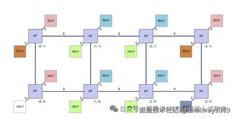
In the mesh architecture, the CMN600 network improves performance through:
1. The mesh architecture layer, through multi-level caches, and designing HNF nodes to snoop caches in clusters, improving performance.
2. The protocol layer, where the CHI protocol supports DMT, DCT, and prefetch functions to enhance performance.
3. The SoC layer, supporting QoS mechanisms to improve performance, where the QoS value is 4 bits, ranging from 0-15, with higher values indicating higher priority.
The dual-chip solution for CMN600AE is as follows: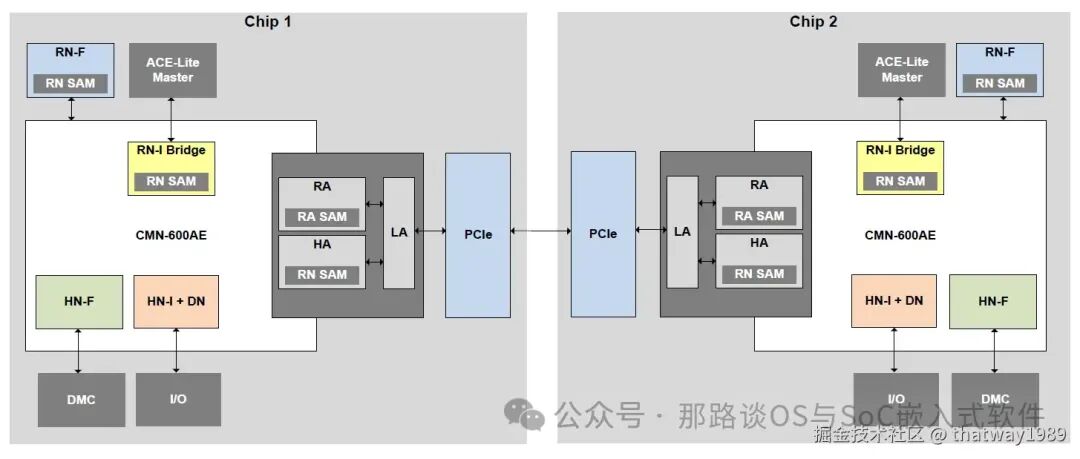 References:
- https://blog.csdn.net/weixin_73077810/article/details/135979534
- https://blog.csdn.net/m0_52840978/article/details/128824794
- https://blog.csdn.net/tujiuguo3994/article/details/134676977
2. NoC Consistency
The above CMN handles the multi-core consistency issues of ARM A cores, while the consistency issues among various heterogeneous cores in the system, such as RISC-V, R, M, etc., need to be maintained by NoC, reference: AI System – 21 AI Chip NoC Bus.
2.1 Introduction
Network on Chip (NoC) interconnects are used to effectively manage data flow between components, providing scalable, low-latency, and high-energy-efficient communication, thus enabling seamless integration of functions such as CPU, GPU, NPU, and other accelerators. NoC can reduce data bottlenecks, improve system performance, and adapt to the increasing complexity in SoC designs.
Cache consistency is central to efficient data sharing between components in SoCs. It is a mechanism that ensures data consistency, preventing bottlenecks and data inconsistencies, ultimately maintaining overall system performance. It ensures that the system runs seamlessly in the background. Engineers who delve into cache consistency will find themselves at the intersection of hardware and software.
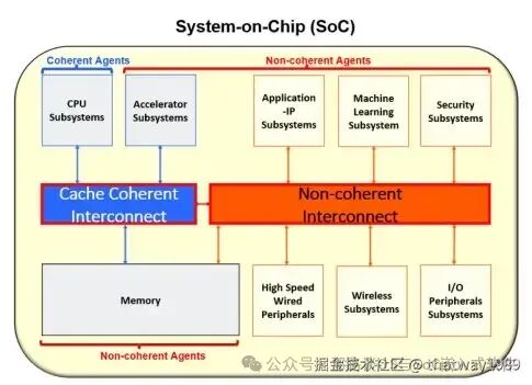
Consistent interconnect ensures that all processes within the system have a unified and consistent view of memory. Consider a system with a machine learning subsystem. In such a setup, the machine learning processor independently manages data flow, and enforcing cache consistency may introduce unnecessary overhead. Therefore, isolation of unique resources may be necessary without necessarily requiring consistent interconnects.
The Arteris product line can be divided into two categories: Ncore and FlexNoC:
- Ncore is a cache-consistent interconnect IP that connects CPUs, accelerators, and memory subsystems, launched in 2016 for heterogeneous computing chips;
- FlexNoC is used to connect peripheral modules, including D2D or C2C parallel interfaces and some extended features (such as safety extensions for automotive applications).
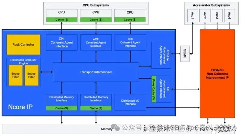
The various configurable monitoring filters of Ncore enable more targeted and simplified consistency management, thereby reducing the overall complexity of the design. This approach ensures efficient and tailored consistency solutions, contributing to overall efficiency.
Reference:
- https://cn.design-reuse.com/articles/55488/optimizing-communication-and-data-sharing-in-multi-core-soc-designs.html
2.2 NOC Components Defined by the CHI Protocol
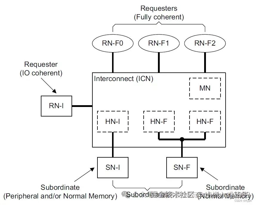
Request Node (RN) can send read/write request transactions to the NoC, with the following types of RN:
1. RN-F is generally a processor core or core cluster node, containing local caches and consistency components (snoopee). Together with the consistency components on the NoC, it maintains the consistency of “cacheable” data (the addresses of this cacheable data are generally of normal attributes); RN-F can send all types of request transactions and supports all types of snoop transactions (not only sending snoop type transactions but also responding to snoop type transactions from the NoC). RN-D generally supports SMMU IO DMA request points, does not contain local caches, and has no snoopee. It can receive and respond to DVM type transactions from RN-F (used for SMMU operations); mainly responsible for sending data consistency-related transactions when performing DMA read/write to main memory. RN-I is similar to RN-D but does not support SMMU. The consistency node HN belongs to the functional components of the NoC, receiving transaction requests from RN, with the following types of HN:
2. HN-F includes a directory or snoop filter to support all types of transaction requests, but does not support DVM type transaction requests. HN-F manages the cache consistency of all RN-F, for example, determining where the latest data for a given address is located, whether in the caches of several RN-F or in the L3 cache of the NoC; for example, before an RN-F writes data, it must first obtain exclusive rights to that address from HN-F (in other words, HN-F assists RN-F in obtaining exclusive rights to the address); HN-F can also be used to manage the order of memory requests, meaning HN-F is a serialization point for memory operations. My understanding: HN-F is used for cacheable normal attribute address ranges. HN-I supports some types of transaction requests, does not manage the data consistency of RN, and is used for the serialization function of PIO operations targeting peripherals. My understanding: HN-I is used for non-cacheable device attribute address ranges. MN is specifically used to receive DVM operations. The SN node can only receive requests from HN, complete related operations, and return response messages.
3. SN-F is used for normal attribute memory, and can also handle non-snoopable read/write, atomic operation requests, and exclusive read/write requests. SN-I is used for device attribute peripherals (or normal attribute memory), and can also handle non-snoopable read/write, atomic operation requests, and exclusive read/write requests.
Note:
These nodes are configurable, and in the NoC, they are configured in hardware, while CMN can be configured in software. For example, -F has a cache to ensure consistency, while -D has no cache and does not guarantee consistency.
Reference: https://blog.csdn.net/lsshao/article/details/128969914
3. Software Perspective
3.1 ARM Memory Consistency
First, the configurable memory attributes of ARM can be found in the ARM manual.
1. Normal memory type attributes apply to most memory in the system. It indicates that the architecture allows hardware to perform speculative data read accesses to these locations, regardless of the access permissions for these locations. To ensure the order of accesses to Normal memory, it is necessary to use memory barrier instructions: DMB .
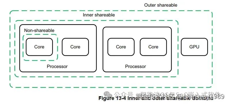
- Each Inner shareable domain contains a set of observers (observers) that are data consistent for each member in that group, used for data access using any member of that group that creates internal shareable attributes (Inner Shareable attribute).
- Each Outer shareable domain contains a set of observers, which are data consistent for each member of that group, used for data access using any member of that group that creates external shareable attributes (Outer Shareable attribute).
- Non-shareable Normal memory: Non-shareable normal memory is a block of Normal memory that can only be accessed by a single CPU
Each Normal memory is also assigned a cache attribute:
- Write-Through Cacheable.
- Write-Back Cacheable.
- Non-cacheable.
2. Device memory type attributes define memory locations where accesses to those locations may cause side effects, or the values returned from loads may vary based on the number of loads executed. Typically, device memory attributes are used for memory-mapped peripherals and similar locations.
- Speculative data accesses are not allowed for any memory location with any Device memory attribute. This means that every memory access to any Device memory type must be generated by the simple sequential execution of the program.
- Writes to any Device memory type must complete within a limited time.
- If the value returned from a memory location of Device memory type changes, and the observers have no explicit memory writes affecting it, that change must also be globally observed by all observers in the system within a limited time. Such changes may occur in peripherals that hold state information.
- Data accesses to Device memory locations are consistent for all observers in the system and are considered externally shareable (Outer Shareable).
- Memory locations with any Device memory attribute cannot be cached.
- For any access to Device memory types, use the DMB instruction to introduce a Barrier-ordered-before relationship on all accesses to a single peripheral or a specified size memory block.
- If a memory location cannot support unaligned memory accesses, then unaligned accesses to that memory location will generate an alignment error during the first stage of the conversion, defining that location as Device.
- Hardware does not prevent speculative instruction fetches from any memory location with any Device memory attribute unless that memory location is also marked as execute-never for all exception levels.
There are four subtypes of Device type, corresponding to different levels of restrictions. The following are the most lenient subtypes:
- Device-GRE
- Device-nGRE
- Device-nGnRE
The strictest subtype is:
- Device-nGnRnE
The letters following Device express the combination of attributes:
(1)Gathering (G, nG). Indicates whether accesses can be merged (G) or not (nG). This means that multiple accesses to the same address may be merged into one access, or multiple small accesses may be merged into one large access.
(2)Re-ordering (R, nR). Indicates whether accesses to the same peripheral can be out of order (R) or not (nR).
(3)Early Write Acknowledgement (E, nE). This attribute determines when a write operation can be considered “completed.” If Early Write Acknowledge (E) is allowed, then as soon as a write operation is visible to other observers, even if that access has not actually reached its destination, that access will still be considered “completed.”
Data Memory Barrier (DMB) is used to prevent specified explicit data accesses from crossing the barrier instruction out of order. All explicit data load or store instructions before the DMB in program order will be observed by all Observers in the specified Shareability domain before data accesses after that DMB in program order.
DSB memory barrier ensures that memory accesses before this DSB must complete before the DSB instruction is executed. Therefore, it is a stronger memory barrier than DMB. The ordering guaranteed by DMB with specified parameters can also be achieved by the same parameters of DSB.
- DMB: can only achieve ordering, cannot persist
- DSB: can persist
- ISB: instruction-level ordering guarantee
Other memory types include:
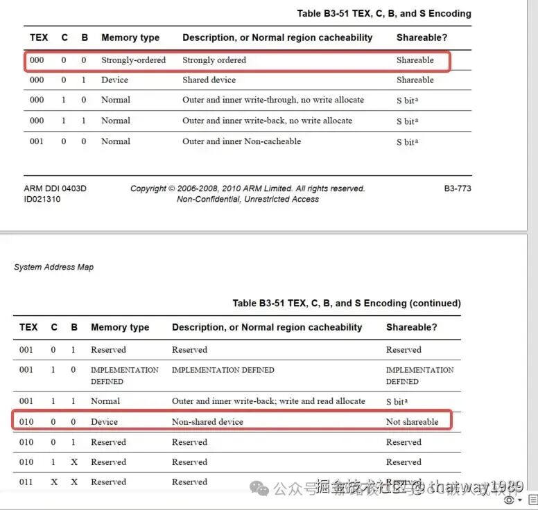
- In M cores, there is strongly-ordered: similar to device but maintains order. In A cores, the device attribute generally has GRE to achieve a similar effect.
Reference:
- https://blog.csdn.net/luolaihua2018/article/details/128986147
- https://vxworks.net/arm/1127-arm-architecture-memory-systems-ordering-and-barriers
3.2 MPU Ensuring Consistency
Generally, ARM M cores will use MPU.
MPU (Memory Protection Unit) is optional under the armv7-m architecture, and our Schumacher M4F supports it. The armv7-m typically supports 8 regions. A region represents a contiguous area.
MPU can be used to define memory space attributes, such as privilege and non-privilege instructions and whether the cache is accessible. It increases system robustness:
- It can prevent users from corrupting data needed by the operating system.
- It can prevent one task from illegally accessing another task’s data, completely isolating tasks.
- It can set critical data areas as read-only, preventing corruption.
- It can detect other unexpected accesses, such as stack overflows, array out-of-bounds, etc.
- MPU can define the attributes of certain specific address areas, which can be defined in many types, such as defining that non-privileged states cannot be assigned.
- If a non-privileged pointer accidentally accesses this address area and attempts to assign a value to that area, it will trigger a MemManage fault or hard fault interrupt, indicating that your program is not allowed to modify that area.
Its registers TEX, C, B can determine memory types, combined as follows:
3.3 Consistency Issues with Device Registers
Some devices are connected to the NoC bus, so when the CPU accesses these device registers, it actually requires DSU->CMN->NoC control for the data to reach the device for configuration. If there is cache consistency in between, the control of the device registers may not take effect.
For example, the consistency issue when the CPU accesses UFS generally occurs in the cooperation between the UFS controller and the CPU. For instance, when the CPU operates the UFS registers, the UFS controller may find that the register settings are incorrect when it works, resulting in an error. This means that the CPU’s operation on the UFS register did not succeed.
Generally, device memory mapping is configured by ARM as Device attributes. However, it is not strongly ordered and persistent, requiring further configuration of Device-nGnRnE or using strongly-ordered. Additionally, the non-cacheable attribute has limitations, only restricting the A core, but CMN and NoC also need to be configured.
In CMN and NoC, these bus accelerations have a pre-acknowledgment mechanism, which needs to be disabled for systems with high consistency. The specific details involve synchronizing the states of these data according to protocols such as ACE/CHI. Two common methods:
- Set CMN or NoC to disable pre-acknowledgment
- Set memory attributes to Device-nGnRnE or use strongly-ordered
Regarding the settings for CMN600 in the ARM official manual:
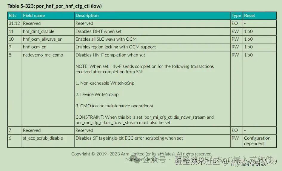
bit8:ncdevcmo_mc_comp will disable pre-acknowledgment after being set, but this will reduce some efficiency.
Pre-acknowledgment is actually a disorder of order, where if the subject is slow to use it, there is no problem. If the subject is fast and uses it, the end has not yet taken effect, leading to timing disorder.
3.4 SRAM Consistency Issues
In SoCs, there are some system-level SRAMs that can be accessed by various cores, sometimes serving as shared memory or storage for firmware execution. However, when it comes to heterogeneous multi-core access to SRAM, there are consistency issues.
- First, during initialization, the SRAM hardware must be powered on before use, otherwise, the data written will read as all zeros for a period, becoming invalid. The hardware has related registers to ensure SRAM is ready.
- When heterogeneous cores access and write to the system SRAM, the contents need to be flashed.
- In the MCN and NoC, the ports such as HN-F and HN-I attributes must be configured correctly.
Other consistency issues with DDR, UFS, ramdisk, etc., are similar to the above problems. Additionally, when encountering these issues, three aspects should be checked:
- Whether the memory type configuration is correct (in core, MPU, CMN, NoC, etc.), memory type configuration can be propagated through protocols, and can be tried one by one
- Order disorder caused by pre-acknowledgment, out-of-order execution, etc.
- Cache consistency, DSB flushing cache, etc.
Additionally, when encountering some performance issues, consistency can also be a starting point. For example, ensuring consistency can be achieved through n methods, using the method with the best performance. It is even possible not to guarantee complete consistency, and to implement some checks in software for fault tolerance.
Postscript:
Consistency issues encompass a lot from both hardware and software perspectives. This article serves as a general summary, while specific details require analysis of software code and hardware manuals, which are quite extensive. Moreover, tools like trace32 and other dump methods should be used to observe the state of memory values at certain moments and to make comparisons.
“Understanding a little about everything, but mastering nothing,
able to do anything, but not excelling at anything,
being a jack of all trades, master of none,
is a common experience for programmers.”
Welcome to leave a message if you have your own public account: Apply for reprint!
Continuously updating pure content, welcome to share with friends, like, collect, view, underline, and comment for communication!
Bonus:
-
This public account provides a WeChat technical exchange group to discuss automotive software technology together (first add WeChat: thatway1989, and note the technical direction of interest).
-
If you need advertising or business cooperation, you can also contact the author.
-
Appreciation of 1 yuan to make friends