 New users can click the “blue text” above to follow us
“Cultivating Young Makers” is an educational practice aimed at fostering innovation, practical skills, and social responsibility. In recent years, this initiative has focused on the needs of students for innovation and creativity, encouraging young people to actively identify problems in their daily lives, engage in independent exploration, and practice hands-on skills.At the 7th “Young Makers” Creative Market, the students from Beijing No. 20 Middle School showcased their unmanned lunar loading and unloading system, which is full of technological and futuristic elements. Let’s take a look!
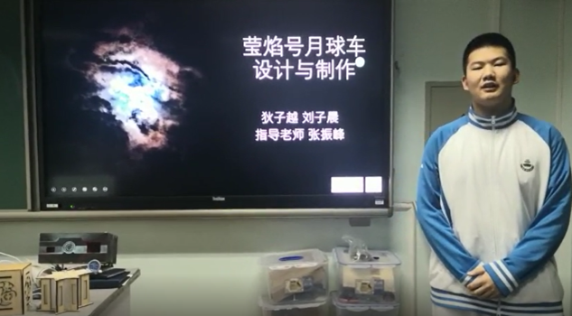
Project Name: Unmanned Lunar Loading and Unloading System
Beijing No. 20 Middle School
Grade 11: Di Ziyue, Liu Zichen
Instructors: Zhang Zhenfeng, Li Liming
01
Design Intent
Technology changes the future—what I want to create, I will create myself. Lunar colonization may soon become a reality. The final product of this project will be applied in a lunar-like environment, capable of transporting as many goods as possible along a predetermined route in the shortest time possible. The entire transportation process is fully automated, with no human intervention.
02
Design Process
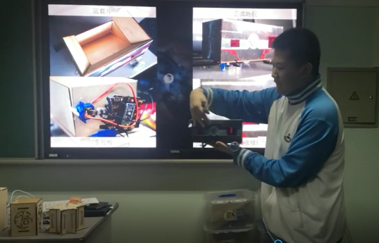
1. Loading Device
This device is the highlight of our group’s achievements. We used our complete Arduino Uno kit for this device. An ultrasonic sensor determines the position of the detection vehicle, and then a relay amplifies the current to control the electromagnet for releasing energy blocks.
At the beginning of the project, we had many ideas for unloading energy blocks, which often determined the structure of the loading device. For the assumed conditions, the unloading requirements were as follows: the unloading device must have a control system independent of the transport device; it must have an independent power supply; it must accommodate a large number of energy blocks; the unloading must be precise, with minimal errors in time and position; and it must be easy to maintain and highly reliable.
Considering the above points, we envisioned two types of solutions: horizontal transfer and vertical drop. After comparison, we ultimately chose the vertical drop method.
Comparison of Horizontal Transfer and Vertical Drop
Horizontal Transfer: Uses a conveyor belt to deliver energy blocks to the transport device.
Vertical Drop: Utilizes gravity to drop energy blocks vertically into the transport device.
The advantages and disadvantages of these two solutions are quite evident. The first solution’s advantage is that using a conveyor belt for energy block transfer is very stable. It will not cause energy blocks to fall during the transfer process due to other reasons. However, the disadvantage of this solution is that it takes too long. To pursue transportation stability, the conveyor belt’s speed cannot be too fast, which significantly affects transportation time. Additionally, this transportation method occupies more space due to the horizontal transfer, including the conveyor belt and supporting structures, compared to the vertical drop method. Given the limited space for the unloading device in our assumed scenario, we did not choose this method.
The second solution’s advantage is speed and smaller footprint, which aligns with the scenario we set at the beginning of the project. However, its disadvantage is instability. Vertical dropping is affected by gravity, wind, and other external environmental factors. But with precise control, we can minimize these impacts.
After selecting the second method as the unloading method, we detailed several sub-methods.
Bridge Type: Place the energy block in a bar shape on the supporting structure. By controlling the motor, the bridge-like supporting surface breaks apart from the middle, allowing the energy block to slide down.
Tipping Type: Use a motor to tip the container holding the energy block, causing the energy block to fall.
Electromagnetic Release Type: Place the energy block in a box-like supporting device, controlling the bottom plate of the box with an electromagnet module. After the ultrasonic sensor determines success, the electromagnet releases its grip, and the bottom plate naturally drops, allowing the energy block to fall. In this method, the distance-measuring sensor’s determination is very sensitive, and we can artificially add a delay command to adapt the energy block to the lunar gravity acceleration of 1/3600, compensating for other environmental errors.
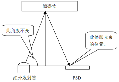
(1) GP2D12 Infrared Distance Sensor:
Since the assumed working environment for this project is the lunar surface, ultrasonic distance sensors become ineffective, so we chose the GP2D12 infrared distance sensor.
It consists of an infrared emitter and a PSD (Position Sensing Device) along with the corresponding calculation circuit. Sharp’s PSD is unique; it can detect minute displacements of light spots falling on it, with a resolution of micrometers. The GP2D12 utilizes this feature to achieve geometric distance measurement. The light beam emitted by the infrared emitter reflects off obstacles and falls on the PSD, forming an isosceles triangle. Using the PSD, we can measure the base of the triangle, and since the two base angles are fixed, determined by the emitter, we can calculate the height, which is the distance we need.
(2) Electromagnet:
Since the voltage provided by the Arduino Uno board is too low, a relay L298 is needed to amplify the current to 12V.
Since we only need to control the electromagnet’s grip and release, a digital signal is sufficient. Therefore, the enable pin of the L298 does not need to be compiled.
In our project, we only need to create a sample, so we selected an electromagnet module with low gripping force.
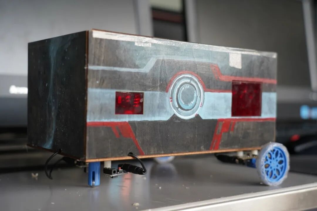
2. Transport Device
(1) Main Structure
The supporting structure of this device is made of three-layer plywood, which we cut ourselves using a laser cutter. Its control system is a set of maker modules centered around the Arduino Nano as the main control board.
To meet the project scenario, we initially envisioned two structural methods: expandable and recessed groove types. After comparison, we ultimately chose the recessed groove type.
Comparison of Expandable and Recessed Groove Types
Expandable Type: The volume of the transport device specified in the project scenario is designed to meet the storage requirements for transportation as much as possible. Clearly, if the transport device has a larger capacity, it will be easier to achieve the goal. This structural method expands the transport device using a motor after it starts running.
Recessed Groove Type: Compared to the first method, this method has stricter spatial arrangements for the transport device. It requires a dense arrangement of 20 energy blocks, power supply, main control board, and various external sensors.
However, the second method is more reliable than the first. If the first method requires structural deformation, the number of motors needed will become a major burden on the power supply, and it is also more prone to damage and failure under the influence of other environmental factors. Therefore, we chose the second method.
We also had two ideas for the unloading structure: tipping and sliding types.
Tipping Type: Use a servo to tip the energy blocks out of the transport container.
Sliding Type: Design the bottom of the transport container as a slope, using a servo to open the bottom flap, allowing the energy blocks to slide down naturally.
Since the project scenario has a clear unloading range, we abandoned the less precise tipping type and chose the second method.
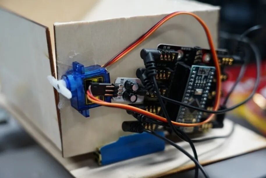
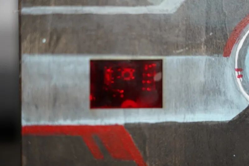
In the transport structure, we used an infrared emitter module, an infrared receiver module, two motor modules, one servo, and four line-following modules.
To make the space as compact as possible, we integrated the transport device’s shell with various sensors, meeting the spatial structure requirements while maintaining aesthetics. The image shows the infrared receiver module of the transport device.
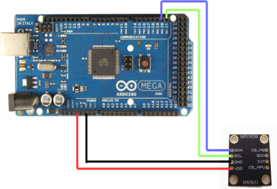
Design Completion of a New Motor Torque Adjustment Method Distinct from Automatic and Manual Modes to Adapt to the Lunar Multi-Slope Environment. By detecting the current state with a horizontal gyroscope and adjusting motor power, this module is designed based on Arduino software, connecting the Arduino Mega2560 main control board, horizontal gyroscope, and motor using C++ language. The Arduino receives feedback data from the horizontal gyroscope, which is then processed to affect the Mega2560 main control board, allowing it to output different analog values based on the MPU’s return values, thereby changing the motor’s power.
(1) Horizontal Gyroscope
This project is based on an intelligent motor module using a horizontal gyroscope, which is one of the most important components in this project as the primary state sensor.
Gyroscopes have many different branches of use, including gyroscopic direction finders, gyroscopic compasses, gyroscopic vertical instruments, gyroscopic stabilizers, laser gyroscopes, MEMS gyroscopes, etc. The data ultimately fed back by the gyroscope in this project will be used to determine the state of the vehicle, so the selected model should be a horizontal gyroscope.
This gyroscope will be used to determine the vehicle’s state, and data such as road slope, vehicle speed, and direction must be detected with high precision. Additionally, this gyroscope sensor needs to connect to the main control board and can input feedback data values as analog values into the program. Moreover, the gyroscope should not be too large in size or weight.
After multiple screenings, I focused on the horizontal gyroscope used in mobile phones, which can accurately determine the current state parameters, can be used for inertial navigation, can output analog values and connect to software, and meets the project’s requirements for small size and weight.
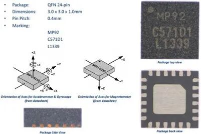
Ultimately, we chose the MPU-9250 as the project equipment. The MPU9250 is a 9-axis motion sensor (Motion Tracking) from Invensense. The term 9-axis here is different from the spatial understanding of 9 axes; it actually consists of three separate 3-axis sensors (accelerometer, gyroscope, magnetometer) combined, totaling 9 axes. In summary, by utilizing the acceleration, angular velocity, and magnetic field strength generated during motion, we can reverse-calculate the actual motion of the object. Since this data can be recognized by computers, it allows for reverse calculation of motion conditions on a computer, enabling the recording of the object’s actual motion information for practical use.
Features of this module include:
1. Outputs a rotation matrix in digital form for 6-axis or 9-axis (requires external magnetic sensor).
2. Has a sensitivity of 131 LSBs/°/sec and a full-scale measurement range of ±250, ±500, ±1000, and ±2000°/sec for the 3-axis angular velocity sensor (gyroscope).
3. Removes sensitivity between the accelerometer and gyroscope axes, reducing the influence of settings and sensor drift.
4. Built-in operation time deviation and magnetic sensing calibration calculation technology, eliminating the need for additional calibration.
5. Includes a digital input synchronization pin (Sync pin) supporting video electronic image stabilization technology and GPS.
6. VDD supply voltage is 2.5V±5%, 3.0V±5%, 3.3V±5%; VLOGIC can be as low as 1.8V±5%.
7. Gyroscope operating current: 5mA, gyroscope standby current: 5uA; accelerometer operating current: 500uA, accelerometer power-saving mode current: 40uA@10Hz.
8. Comes with a 1024-byte FIFO, which helps reduce system power consumption.
9. Supports IIC communication interface up to 400KHz.
10. Ultra-small package size: 4x4x0.9mm.
The most important feature of this module is that it can be developed using Arduino, which other MPU models cannot do, hence this model was chosen.
(2) Arduino Mega 2560
The Arduino Mega2560 is a core circuit board with a USB interface, featuring 54 digital input/output pins, suitable for designs requiring a large number of IO interfaces. The processor core is the ATmega2560, which has 54 digital input/output pins (15 of which can be used as PWM outputs), 15 analog inputs, 4 UART interfaces, a 16MHz crystal oscillator, a USB port, a power socket, an ICSP header, and a reset button. It also supports SPI, IIC, and UART serial communication, allowing it to perceive the environment through various sensors, providing great flexibility and high expandability.
Using this main control board, programs compiled on a computer can be uploaded directly to the ATmega2560. Once uploaded, it can run the program stored in the ATmega2560 even when not connected to the computer.
Arduino language is based on C/C++, essentially being basic C language, with Arduino language simply functionally encapsulating parameters related to AVR microcontrollers.
(3) Language Compilation
-
Ø Detecting the feedback data from the MPU-9250
The MPU-9250 has a corresponding library of functions and also includes libraries for the I2C communication protocol. After importing, programming can be done according to project requirements. The feedback data required for this project includes 3-axis angular velocity and 3-axis acceleration.
The specific language is as follows:
1. int val;//Define variableval
2. #include “Wire.h”
3. //#include “I2Cdev.h”
4. #include “MPU6050.h”
5. MPU6050 accelgyro;
6. int16_t ax, ay, az;//Acceleration
7. int16_t gx, gy, gz;//Angular velocity
8. int16_t mx, my, mz;//Magnetic force
9.
10. bool blinkState = false;
11. int ledpin=13;//Define digital interface13
12. void setup() {
13. Wire.begin();
14. // put your setup code here, to run once:
15. Serial.begin(9600);
16. pinMode(10,OUTPUT);}
17.
18. }
19.
20. void loop() {
21. // put your main code here, to run repeatedly:
22. //val=Serial.read();//Read the command or character sent from the PC to the Arduino and assign it toval
23. //if(val==’R’)//Check if the received command or character is“R”.
24. //{//If the received character is“R”.
25. accelgyro.getMotion9(&ax, &ay, &az, &gx, &gy, &gz, &mx, &my, &mz);
26. /*digitalWrite(ledpin,HIGH);//Light up digital13 pin LED.
27. delay(100);
28. digitalWrite(ledpin,LOW);//Turn off digital13 pin LED
29. delay(100);
30. Serial.print(“a/g: “);*/
31. Serial.print(ax); Serial.print(“\t”);
32. Serial.print(ay); Serial.print(“\t”);
33. /* Serial.print(az); */Serial.print(“\t\t”);
34. /*erial.print(gx); Serial.print(“\t”);
35. // Serial.print(gy); Serial.print(“\t”);
36. /*Serial.print(gz);*/Serial.println();
/*Serial.print(mx); Serial.print(“\t”);
38. Serial.print(my); Serial.print(“\t”);
Serial.println(mz);*/
In lines 1-4, the required library functions are referenced.
Lines 6-8 set various variables.
Line 15 sets the baud rate.
Line 16 defines the output port.
After that, feedback of various data follows.
Data obtained:
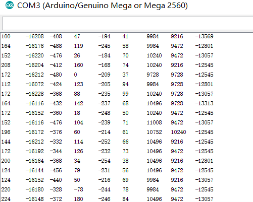
This is the angular velocity and acceleration data obtained from the MPU-9250. By applying the tilt angle formula, we can determine the current state.
-
Ø Horizontal Gyroscope Feedback Data Determination Statement
Determining the current state based on feedback data is not difficult, using a “while” statement suffices.
while ( ( ( ay ) > ( 5500 ) ) )
{
analogWrite(10 , 100);
}
while ( ( ( ay ) > ( 10000 ) ) )
{
analogWrite(10 , 255);
}
Thus, the language can categorize motor power into multiple levels, optimizing energy distribution.
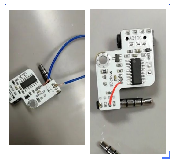
Real Image of the Intelligent Motor
03
Innovation & Novelty
The application environment of this device is novel, as it is designed for the moon. The entire process is automated, requiring no human intervention, and uses ultrasonic waves as the interaction medium, a method rarely used in material transportation. The height and position of the loading device can be adjusted to accommodate different transport devices and ground environments. The open design of the transport device allows it to carry more materials while also being suitable for use in the absolutely windless environment of the moon.
04
Reflections and Gains


The unexpected situations that arose during the experiment constantly tested our patience and perseverance. With the guidance and help of our teachers, the team members engaged in continuous thinking, careful design, learning new knowledge, hands-on practice, identifying problems, and solving them, ultimately completing the project. Throughout the process of creating the project, we enhanced our practical skills, innovative awareness, and expressive abilities, while also broadening our horizons.
05
Teacher’s Reflections
During the guidance of the “Unmanned Lunar Loading and Unloading System” project, I observed students integrating interdisciplinary theoretical knowledge and technology. By understanding cutting-edge national technology, engaging in brainstorming discussions, identifying existing problems, clarifying the issues to be solved, proposing basic design requirements, and after design analysis, presenting preliminary conceptual plans, they utilized manual drawing tools and drawing software for design expression, and employed manual and mechanical processing tools for production. With the help of teachers, they gradually optimized their projects. Through this project practice, students developed an interdisciplinary perspective, systematically applying knowledge and methods from multiple disciplines to analyze and solve real-world scientific, technological, and engineering problems, enhancing their innovative capabilities and developing comprehensive qualities.
(Contributors: Di Ziyue, Liu Zichen, Zhang Zhenfeng, Li Liming from Beijing No. 20 Middle School)
Expert Review
Chen Henghua Principal (Beijing Municipal People’s Congress Representative, Principal of Beijing No. 20 Middle School Education Group) communicating with students
The “Unmanned Lunar Loading and Unloading System” is a project completed by students Di Ziyue, Liu Zichen, and others in the 11th grade under the guidance of teachers at our school, submitted to the 7th “Young Makers” Creative Market in Beijing. This project is also a result of the school’s “Deep Space Exploration Thematic Series Course,” which uses the lunar environment as a scenario to guide students in systematically analyzing and solving scientific, technological, and engineering problems related to unmanned loading and unloading systems, integrating knowledge and methods from multiple disciplines to design and complete fully automated operations of the loading and unloading system. The establishment of this course helps students develop an interdisciplinary perspective, enhance engineering thinking, improve innovative capabilities, and develop comprehensive qualities, making it one of the courses that promote moral, intellectual, physical, aesthetic, and labor education in parallel.
The Beijing Youth Science and Technology Innovation Academy conducts “Young Maker Cultivation,” guiding teachers to help students choose themes based on regular courses and subject teaching systems for in-depth exploration, enhancing students’ innovative awareness, practical abilities, and social responsibility, which is a beneficial attempt at innovating talent cultivation methods.
Organized by: Zhang Yi
Coordinated by: Wang Xin
Designed by: Wang Xin