Background Introduction
In embedded systems, UART serial ports are commonly used for debugging and communication. Typically, there are no specific requirements for the baud rate of the debugging serial port, with a common configuration being 115200 8N1. Besides debugging, UART serial ports can also serve as data communication interfaces for interconnecting with other boards or modules. When UART is used as a data communication interface, there are higher demands on the transmission bandwidth, and the original baud rate of 115200 may not meet such requirements. The following will introduce the considerations for using Altera A10 SoC HPS UART as a data communication interface.
HPS UART Baud Rate Configuration
1. Configuring the Baud Rate Register rbr_thr_dll
Altera A10 SoC HPS provides two UART interfaces: UART 0 and UART 1. The fixed base addresses are shown in the figure below (Figure 1):
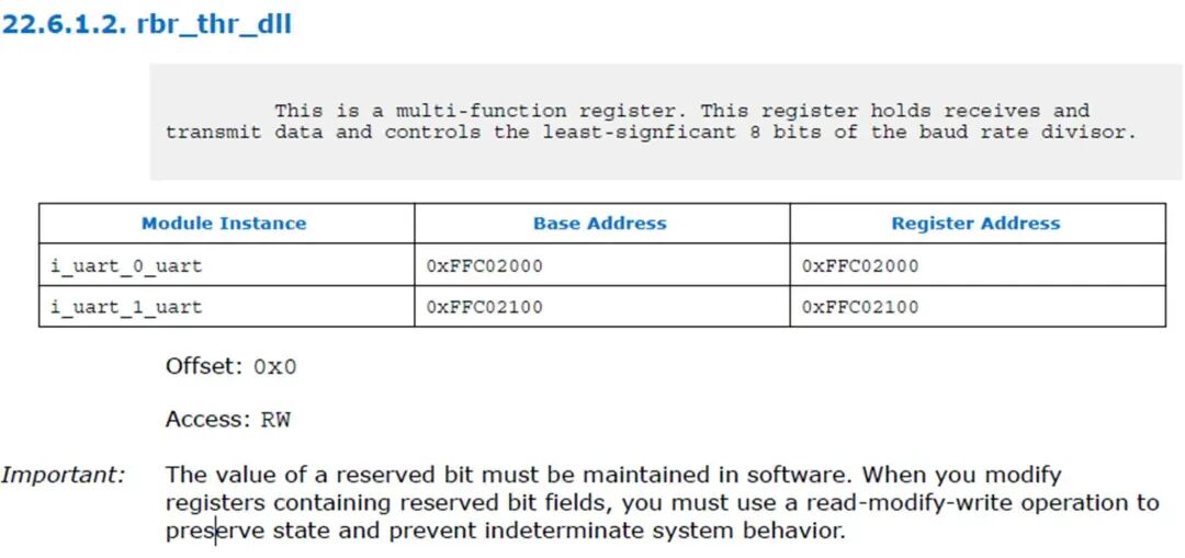 Figure 1 Fixed Base Address
According to the data sheet, the division value = serial port clock ÷ (16 * baud rate). Since the division value is likely to be a decimal, it needs to be rounded to the nearest integer and written into the low 8 bits DLL and high 8 bits DLH of the division value register. As a result, the actual baud rate may differ from the expected baud rate, as shown in the figure below (Figure 2):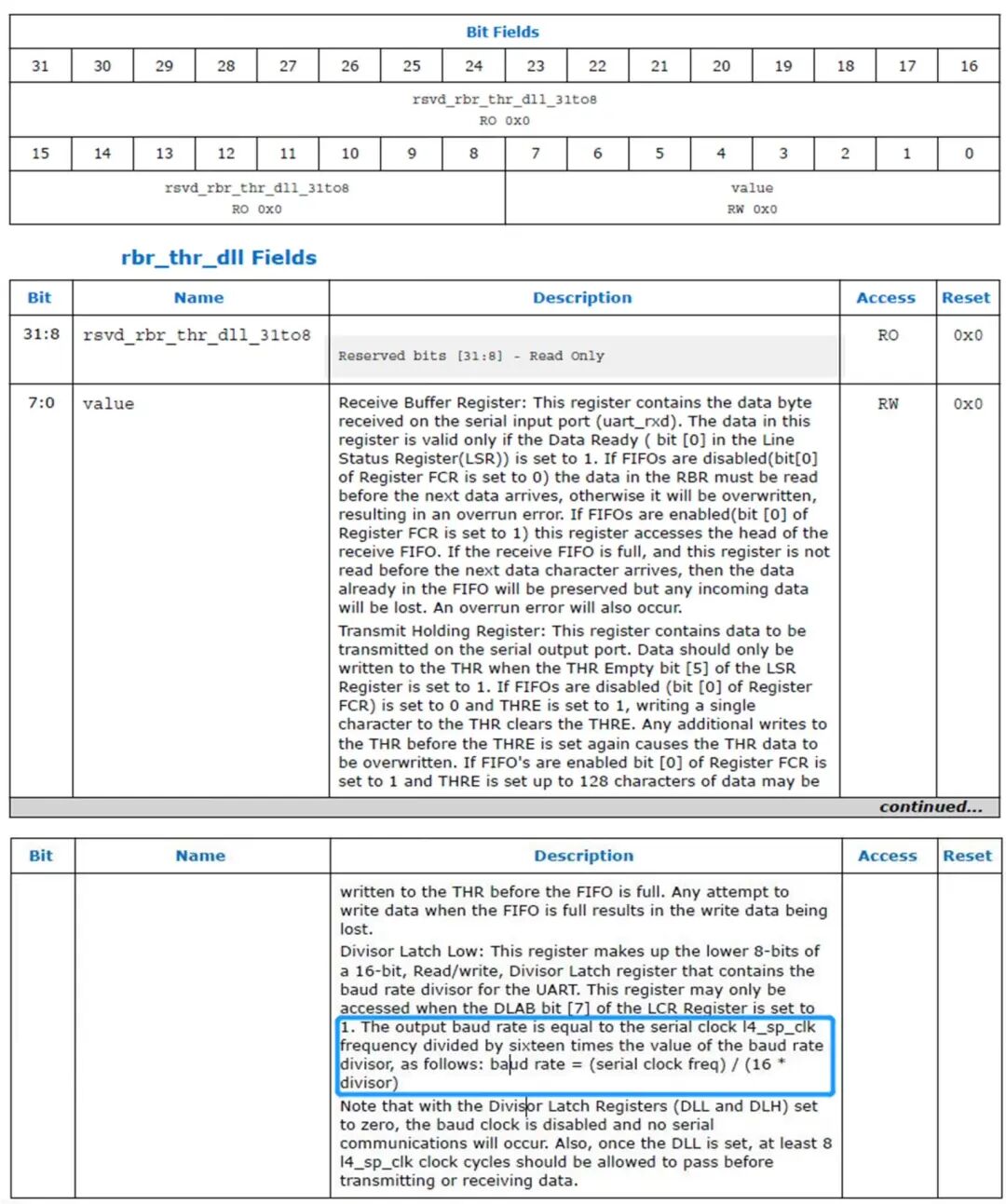 Figure 2 DLL Register
2. Baud Rate Error Control
It is important to note that when the SoC FPGA board’s UART serial port is used as a data transmission interface to communicate with other boards or modules, the baud rates of both UART serial ports should be as equal or close as possible, with a difference controlled within 2%. If the difference is too large, the data transmitted by the UART serial port may not be correctly recognized by the receiving UART serial port, potentially leading to data transmission failure.
Practical Application Case
To illustrate this application scenario, we will explain it through a real example from a customer. The customer used the Altera A10 SOC FPGA, with HPS connected to a module via UART 0 for data transmission, with the initial configuration shown in the figure below (Figure 3):
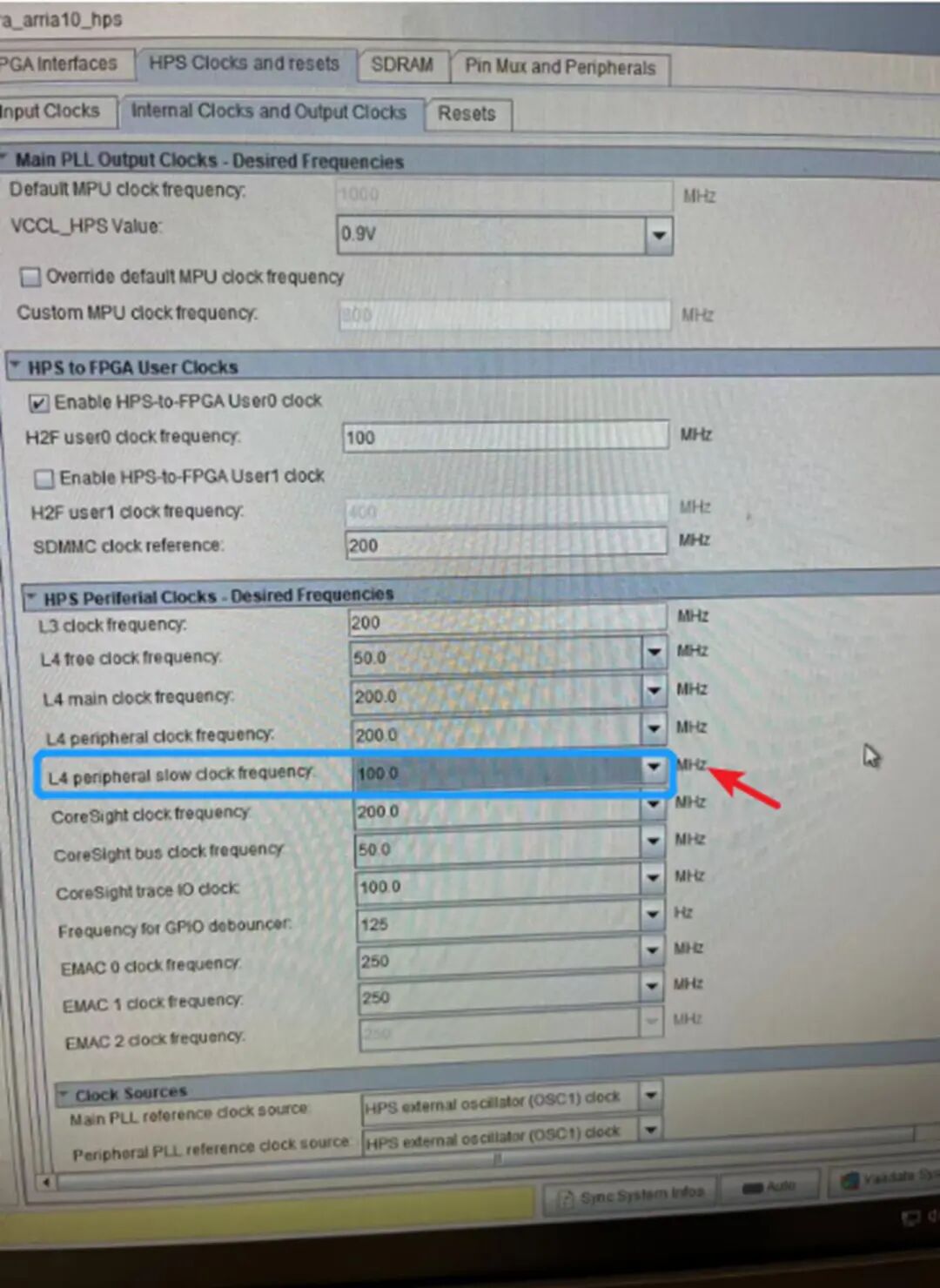 Figure 3 Initial ConfigurationFrom the above figure, it can be seen that the Qsys HPS clock and reset configuration, with the customer configuring the l4_sp clock to 100MHz and the division value to 3, resulting in a baud rate of 100 ÷ (16 * 3) = 2.083M. However, the oscilloscope test showed 2.084M, as marked in the blue box in the figure below (Figure 4):
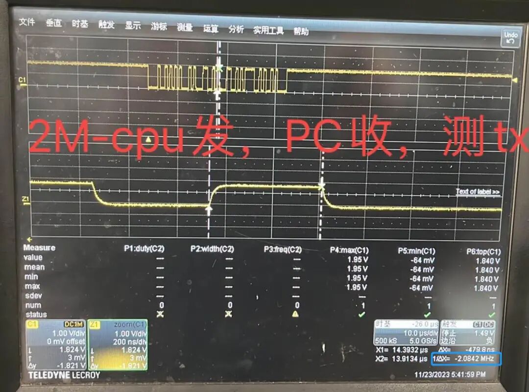 Figure 4 Oscilloscope Test ValueHowever, the baud rate of the external module connected to the HPS UART serial port was 2.00M, resulting in a 4% difference, which caused communication failure between the two boards. After adjusting the configuration parameters, a suitable clock and division value were finally found, as shown in the figure below (Figure 5):
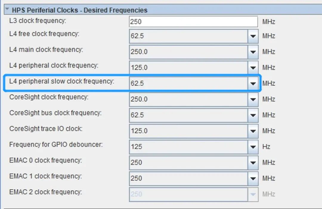 Figure 5 Suitable Clock and Division ValueThe customer adjusted the l4_sp clock from 100MHz to 62.5MHz, and the division value was adjusted to 2, resulting in a baud rate of 62.5 ÷ (16 * 2) = 1.95M, with a baud rate difference of about 2%. Ultimately, the UART communication between the two boards was restored, with a data bandwidth of approximately 0.19MB/S.
Conclusion
This article introduced the application of Altera A10 SoC HPS UART as a data communication interface, focusing on baud rate configuration, division value calculation, and debugging techniques in practical applications. By properly configuring the clock and division values, developers can achieve high-speed and stable UART data transmission.
For more information about Altera products and solutions, please contact the local office of Junlong Technology or email [email protected]. Junlong Technology is willing to provide you with more detailed technical answers.