Click the blue text
PLC Automation Exchange
Follow us
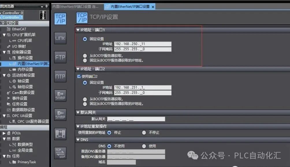
1. Overview of Application ScenariosIn industrial automation projects, it is often necessary to achieve data communication between different devices. The Omron NX102-1200 PLC acts as a master station, reading floating point data from slave devices (such as sensors, instruments, other PLCs, etc.) via the MODBUS TCP protocol, which is a common application scenario.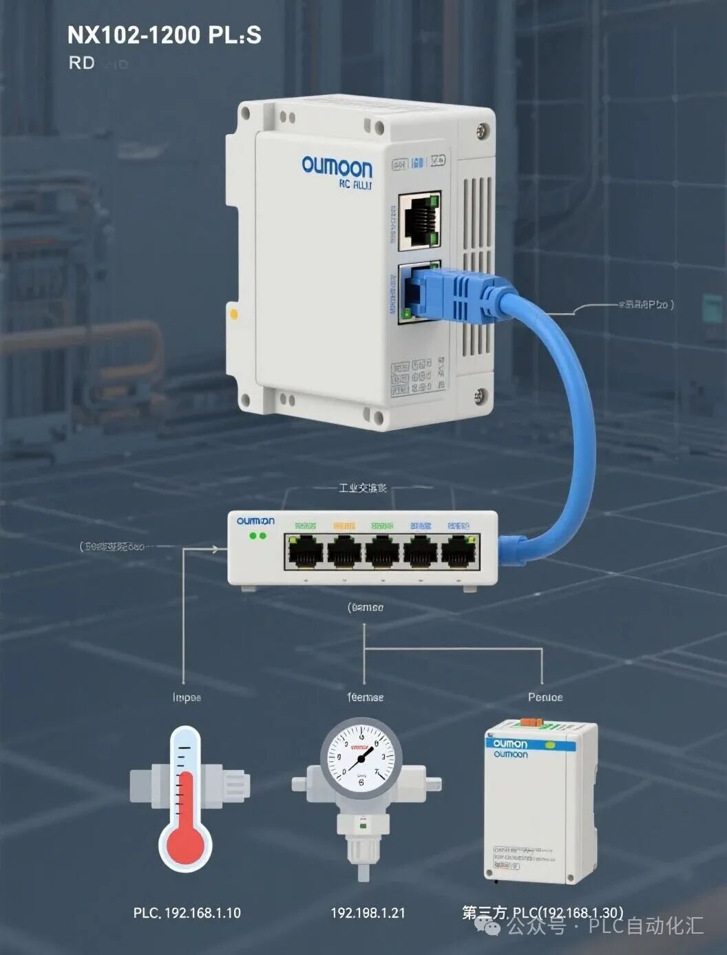 This article will detail how to use ST language to write a program that enables the NX series PLC to read floating point numbers as a MODBUS TCP master.2. Hardware Connection and Configuration2.1 Hardware Requirements· Omron NX102-1200 PLC· Slave devices that support MODBUS TCP protocol· Ethernet switch and cables2.2 Sysmac Studio Configuration1. Create a Socket connection: · Go to “Configuration and Settings” → “Communication Settings” → “EtherNet/IP Port Settings” · Add a Socket connection, set to client mode · Fill in the IP address and port number of the slave device (default 502)2. Set communication parameters: · Select MODBUS/TCP as the protocol type · Set an appropriate timeout (usually 5-10 seconds)
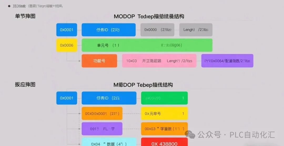
 3. MODBUS TCP Communication Principles3.1 Floating Point Storage FormatThe floating point number in the MODBUS TCP protocol occupies 2 consecutive 16-bit registers (4 bytes) and is stored in IEEE 754 standard format.3.2 Request Message StructureField Length DescriptionTransaction ID 2 bytes Increments with each communicationProtocol ID 2 bytes Fixed at 0Length 2 bytes Length of subsequent dataUnit ID 1 byte Address of the slave deviceFunction Code 1 byte 03: Read Holding RegistersStarting Address 2 bytes Starting address of the registers to be readRegister Count 2 bytes Number of registers to be read3.3 Response Message StructureField Length DescriptionTransaction ID 2 bytes Corresponding to the requestProtocol ID 2 bytes Fixed at 0Length 2 bytes Length of subsequent dataUnit ID 1 byte Address of the slave deviceFunction Code 1 byte 03: Read Holding RegistersByte Count 1 byte Number of bytes of subsequent dataData N bytes Data read
 4. Implementation of ST Language Program4.1 Variable Definitions// MODBUS Communication VariablesReadTrigger: BOOL; // Read trigger signalReadDone: BOOL; // Read completion flagReadError: BOOL; // Read error flagErrorCode: UINT; // Error code// Message BuffersSendBuffer: ARRAY[0..11] OF BYTE; // Send bufferRecvBuffer: ARRAY[0..255] OF BYTE; // Receive buffer// Data VariablesTransactionID: UINT := 0; // Transaction IDFloatValue: REAL; // Parsed floating point valueSlaveIP: STRING := ‘192.168.1.100’; // Slave IP address
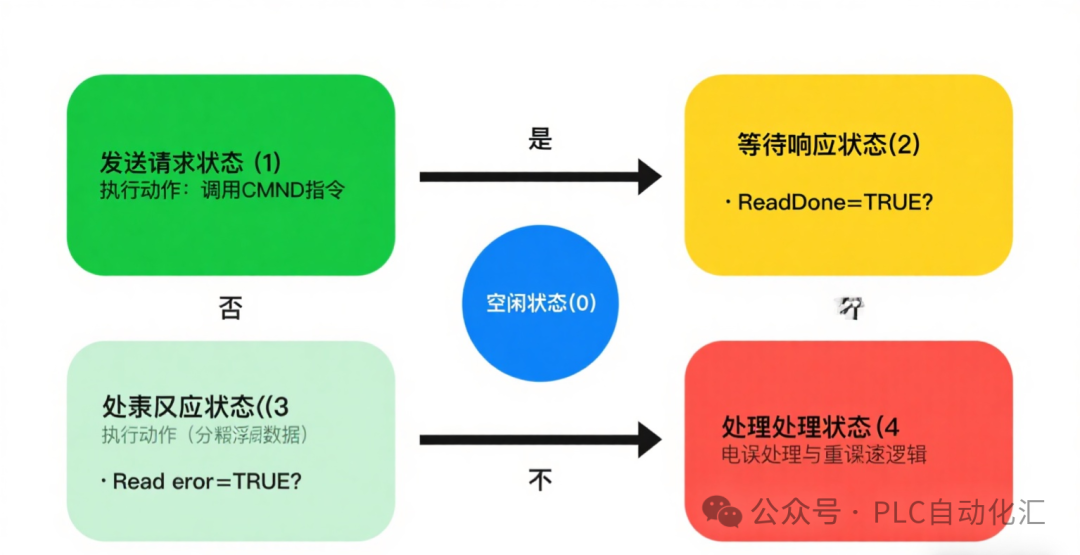
 4.2 Constructing MODBUS Request Message// Construct MODBUS TCP request messageFUNCTION BuildModbusRequestVAR_INPUT StartAddress: UINT; // Starting address RegisterCount: UINT; // Number of registersEND_VARVAR TempTxID: UINT;END_VAR// Update Transaction IDTransactionID := TransactionID + 1;IF TransactionID > 65535 THEN TransactionID := 1;END_IF;TempTxID := TransactionID;// Construct message headerSendBuffer[0] := BYTE(TempTxID SHR 8); // High byte of Transaction IDSendBuffer[1] := BYTE(TempTxID AND 16#FF); // Low byte of Transaction IDSendBuffer[2] := 16#00; // High byte of Protocol IDSendBuffer[3] := 16#00; // Low byte of Protocol IDSendBuffer[4] := 16#00; // High byte of LengthSendBuffer[5] := 16#06; // Low byte of Length (6 bytes following)SendBuffer[6] := 16#01; // Unit ID (slave address)SendBuffer[7] := 16#03; // Function code: Read Holding Registers// Register address and countSendBuffer[8] := BYTE(StartAddress SHR 8); // High byte of addressSendBuffer[9] := BYTE(StartAddress AND 16#FF); // Low byte of addressSendBuffer[10] := BYTE(RegisterCount SHR 8); // High byte of countSendBuffer[11] := BYTE(RegisterCount AND 16#FF); // Low byte of count4.3 Sending MODBUS Request// Send MODBUS requestIF ReadTrigger AND NOT ReadDone AND NOT ReadError THEN // Construct request to read 400101-400102 BuildModbusRequest(100, 2); // 100 corresponds to 400101, read 2 registers // Execute CMND instruction to send request CMND( Enable := TRUE, SocketID := 1, // Consistent with configured Socket connection ID Command := SendBuffer, Response := RecvBuffer, Timeout := T#5S, Done => ReadDone, Error => ReadError, ErrorCode => ErrorCode );END_IF;4.4 Parsing Response Data// Parse MODBUS responseIF ReadDone THEN // Check response validity IF (RecvBuffer[5] >= 9) AND (RecvBuffer[7] = 16#03) THEN // Big-Endian byte order conversion FloatValue := DWORD_TO_REAL( SHL(ULINT(RecvBuffer[9]), 24) OR SHL(ULINT(RecvBuffer[10]), 16) OR SHL(ULINT(RecvBuffer[11]), 8) OR ULINT(RecvBuffer[12]) ); // Output debug information // (In actual projects, logging can be added) ELSE // Response format error ReadError := TRUE; ErrorCode := 16#FFFE; // Custom error code: Response format error END_IF; // Reset trigger signal ReadTrigger := FALSE;END_IF;4.5 Error Handling Program// Error handlingIF ReadError THEN CASE ErrorCode OF 16#0101: // Connection timeout // Retry logic can be added 16#0301: // Illegal function code // Check function code settings 16#0302: // Illegal data address // Check register address 16#FFFE: // Response format error // Check slave device response format ELSE: // Other error handling END_CASE; // Reset error flag (can be adjusted as needed) ReadError := FALSE; ReadDone := FALSE;END_IF;5. Program Structure Design5.1 Program Organization Unit (POU) Structure// Main ProgramPROGRAM MainModbusMasterVAR // State machine variables CurrentState: INT := 0; RetryCount: INT := 0;END_VARCASE CurrentState OF 0: // Idle state IF ReadTrigger THEN CurrentState := 1; // Transition to sending state END_IF; 1: // Sending request // Call send program CurrentState := 2; // Transition to waiting state 2: // Waiting for response IF ReadDone THEN CurrentState := 3; // Transition to processing state ELSIF ReadError THEN CurrentState := 4; // Transition to error handling state END_IF; 3: // Processing response // Call parsing program CurrentState := 0; // Return to idle state 4: // Error handling // Call error handling program IF RetryCount < 3 THEN RetryCount := RetryCount + 1; CurrentState := 1; // Retry ELSE RetryCount := 0; CurrentState := 0; // Return to idle state END_IF;END_CASE;
 6. Debugging and Troubleshooting6.1 Common Issues and Solutions1. Connection Failure · Check cable connections · Confirm slave IP address and port number · Verify that the slave MODBUS service is enabled2. Response Timeout · Increase the timeout for the CMND instruction · Check network communication quality3. Data Parsing Error · Confirm byte order (Big-Endian/Little-Endian) · Verify the floating point format of the slave (IEEE 754)4. Address Mapping Error · Confirm the mapping relationship between MODBUS addresses and slave device addresses6.2 Debugging Tips1. Use Wireshark for packet analysis · Filter condition: tcp.port == 5022. Add debug information output · Add status logging in the program · Use the debugging features of Sysmac Studio3. Simulation Testing · Use Modbus Slave software to simulate slave devices · Gradually verify the communication process7. ConclusionThis article provides a complete implementation plan for the Omron NX102-1200 PLC to read floating point numbers as a MODBUS TCP master, including:1. Hardware Configuration: Correct network connections and Sysmac Studio settings2. Communication Principles: MODBUS TCP protocol message structure3. Program Implementation: Complete communication program written in ST language4. Error Handling: Comprehensive exception handling mechanism5. Debugging Tips: Methods for quickly locating and resolving issuesWith the guidance of this article, you can quickly implement communication between the Omron NX series PLC and MODBUS TCP slave devices, reliably reading floating point data. A friendly reminder: In practical applications, please adjust the byte order and address mapping according to the specific specifications of the slave device and conduct thorough testing and validation. If you encounter any issues during implementation, feel free to leave a comment for discussion!Feel free to share, bookmark, like, and check it out! Let’s discuss your views on Modbus TCP communication in the comments!
If you want to learn Siemens SCL programming, you can purchase the first book below; if you want to learn ladder diagrams, you can purchase the second book, which has detailed examples from basics to entry level.
Your support is the motivation for my writing, thank you all, and I wish you success and happiness in your work!
Recommended Reading:
- Using all your strength! Nine-step guide to stable operation of Siemens PLC
- Siemens S7-1500 PLC Troubleshooting: Transform into an industrial “doctor” to quickly “cure” production line downtime!
- [10-Year Siemens PLC Veteran Upgrade Path] From screwing in modules to mastering communication architecture: My blood and tears technical stack guide
- Three “weapons” of servo motors: Detailed explanation of position/velocity/torque control (with Siemens SCL practical code)
- Core Secrets of Siemens PLC Programming: What are FB, FC, DB, OB? You will understand after reading this!
- Why can’t Siemens PLC engineers with a monthly salary of 20,000 stay? The “career burnout” behind high salaries is consuming this industry!
- Siemens PLC Programming: Ladder Diagram vs SCL, which one is for you? A comprehensive entry guide + practical code!
- Say goodbye to “spaghetti code”! Siemens PLC sequential programming “three-step method”, double efficiency without pitfalls!
- Siemens SCL communication heartbeat monitoring: Industrial-grade heartbeat program practical guide
- Siemens 1200 and Weintek tag communication: Say goodbye to manual address filling, this “smart translator” makes debugging three times faster!
- Siemens SCL Practical: Step-by-step guide to writing station control function blocks
- Siemens S7-1200 Mixed Programming Practical: The golden combination rules of SCL and LAD
- Electrical Automation Encirclement: Ten years of hard work for this heartfelt industry experience summary
- Siemens SCL workstation control program: Start-stop control + three-color light + buzzer alarm
- Mitsubishi FX3U PLC Dual Pump Constant Pressure Water Supply Explained: Frequency + Industrial Frequency Intelligent Switching + Safety Emergency Stop System
- Electrical Automation Major Graduation Guide:
- Employment direction and salary prospects fully analyzed
- Electrical Automation Associate Graduates: Starting salary not inferior to undergraduates? Full disclosure of the technical counterattack roadmap!
- Siemens S7-200 SMART Free Port Communication Explained: Flexible serial communication solution introduction
- Siemens SCL Full-Function Servo Control Ultimate Solution: 8 Motion Modes + 5 Safety Protections
- Let data speak! A scientific guide for choosing majors for science vs. liberal arts students (with employment salary & trend analysis)
Sharing allows more people to see

Like
Bookmark
Share