
Click the blue text
Follow us
Introduction
With the continuous development of motor control technology, communication methods have become increasingly important. Choosing the appropriate communication method is crucial for obtaining real-time motor parameters. Today, we will introduce SPI communication, which is key for data transmission between the motor and the AS5047P encoder.
1. SPI Communication Principle
SPI stands for Serial Peripheral Interface, which is a high-speed, full-duplex, synchronous communication bus. This allows data to be sent and received simultaneously. SPI does not define a speed limit and can typically reach or exceed 10M/bps.
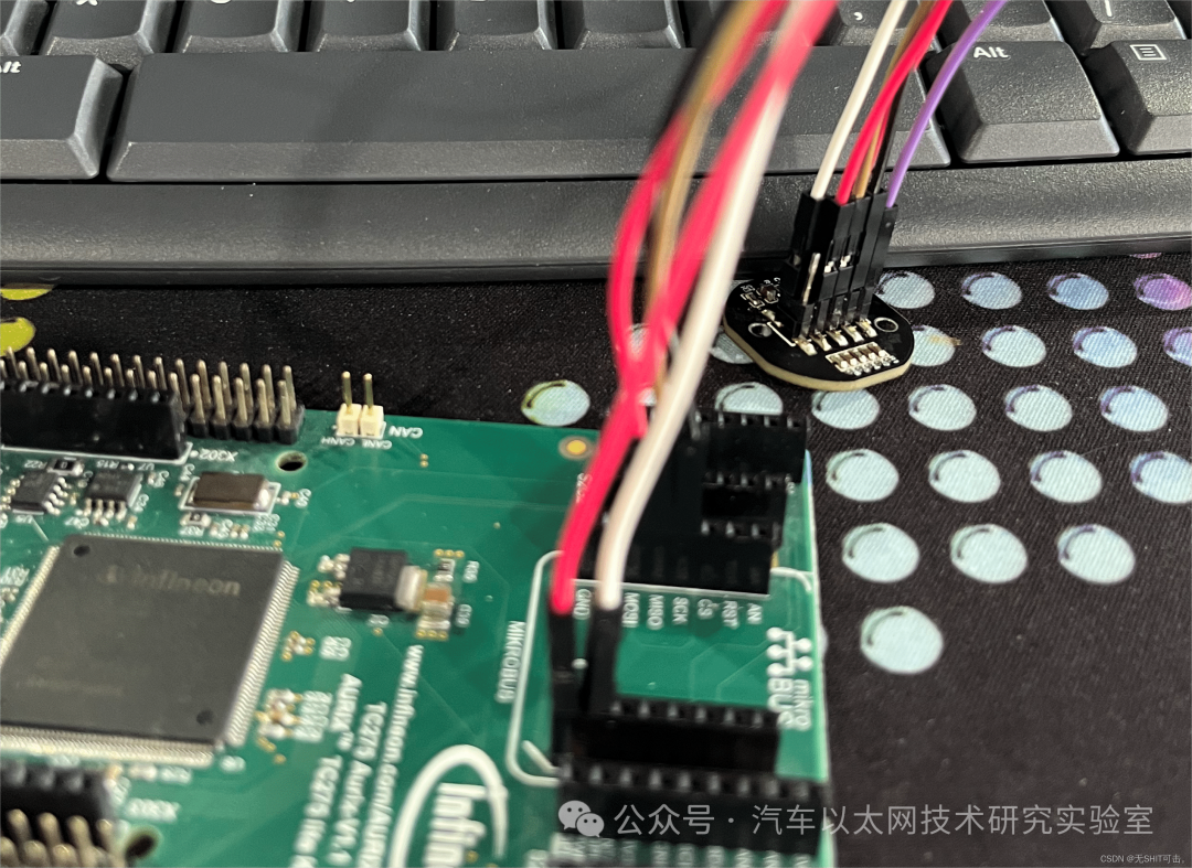
SPI operates in a master-slave mode, usually consisting of one master module and one or more slave modules (SPI does not support multiple masters). Today, we will discuss single master-slave communication, where the TC275 chip acts as the master and exchanges data with the slave AS5047P encoder, as shown in the figure.
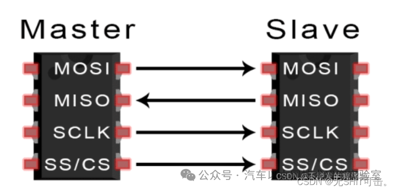
SPI communication requires at least four lines: MISO (Master Input Slave Output), MOSI (Master Output Slave Input), SCLK (Serial Clock), and CS/SS (Chip Select/Slave Select):
-
MISO (Master Input Slave Output): Data input from the master device, data output to the slave device;
-
MOSI (Master Output Slave Input): Data output from the master device, data input to the slave device;
-
SCLK (Serial Clock): Clock signal generated by the master device;
-
CS/SS (Chip Select/Slave Select): Slave device enable signal controlled by the master device. In a master-slave configuration, CS/SS is the control signal indicating whether the slave chip is selected by the master chip. The master chip’s operations on the slave chip are only valid when the chip select signal is at the predetermined enable state (high or low).
This briefly introduces the basic working principle of SPI communication. For a deeper understanding of SPI communication, you can refer to the following article: In-depth Understanding of SPI Communication.
2. Related Code Configuration
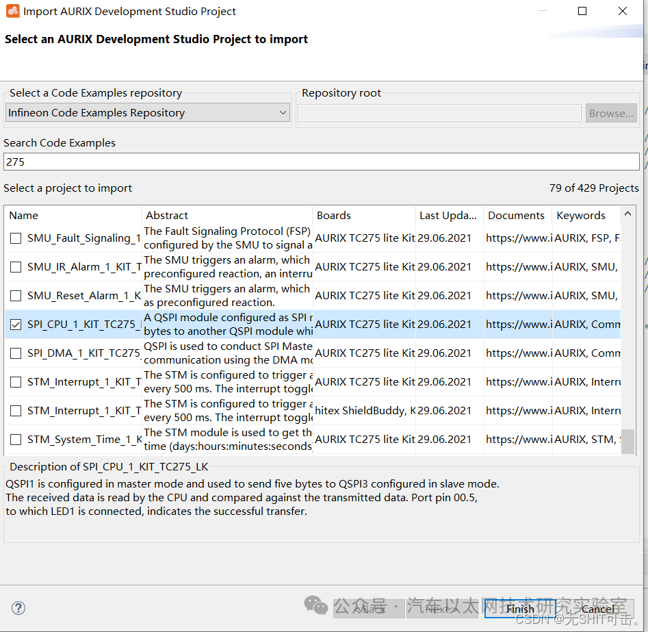
First, import the relevant SPI communication code into Infineon’s IDE. Here, I will use the TC275 chip as an example to import the SPI communication example, as shown in the figure:
The configuration will focus on three aspects: pin configuration, clock parameters, and data exchange code.
1. Pin and Chip Select Configuration
The code is as follows:
-
#define CSPin &MODULE_P33,10
-
void initQSPI3Master(void)
-
{
-
IfxQspi_SpiMaster_Config spiMasterConfig; /* Define a Master configuration */
-
// IfxQspi_SpiMaster_initModuleConfig(&spiMasterConfig, QSPI1_MASTER); /* Initialize it with default values */
-
IfxQspi_SpiMaster_initModuleConfig(&spiMasterConfig, QSPI3_MASTER);
-
spiMasterConfig.base.mode = SpiIf_Mode_master; /* Configure the mode */
-
/* Select the port pins for communication */
-
const IfxQspi_SpiMaster_Pins qspi3MasterPins = {
-
// &IfxQspi1_SCLK_P10_2_OUT, IfxPort_OutputMode_pushPull, /* SCLK Pin (CLK) */
-
// &IfxQspi1_MTSR_P10_3_OUT, IfxPort_OutputMode_pushPull, /* MasterTransmitSlaveReceive pin (MOSI) */
-
// &IfxQspi1_MRSTA_P10_1_IN, IfxPort_InputMode_pullDown, /* MasterReceiveSlaveTransmit pin (MISO) */
-
&IfxQspi3_SCLK_P33_11_OUT, IfxPort_OutputMode_pushPull, /* SCLK Pin (CLK) */
-
&IfxQspi3_MTSR_P33_12_OUT, IfxPort_OutputMode_pushPull, /* MasterTransmitSlaveReceive pin (MOSI) */
-
&IfxQspi3_MRSTD_P33_13_IN, IfxPort_InputMode_pullDown, /* MasterReceiveSlaveTransmit pin (MISO) */
-
IfxPort_PadDriver_cmosAutomotiveSpeed3 /* Pad driver mode */
-
};
-
spiMasterConfig.pins = &qspi3MasterPins; /* Assign the Master’s port pins */
-
/* Set the ISR priorities and the service provider */
-
spiMasterConfig.base.txPriority = ISR_PRIORITY_MASTER_TX;
-
spiMasterConfig.base.rxPriority = ISR_PRIORITY_MASTER_RX;
-
spiMasterConfig.base.erPriority = ISR_PRIORITY_MASTER_ER;
-
spiMasterConfig.base.isrProvider = IfxSrc_Tos_cpu0;
-
/* Initialize the QSPI Master module */
-
IfxQspi_SpiMaster_initModule(&g_qspi.spiMaster, &spiMasterConfig);
-
}
Here, I configured the four pins required for SPI: MISO, MOSI, SCLK, and CS, with particular attention to configuring the chip select pin: #define CSPin &MODULE_P33,10.
2. Clock Parameter Configuration
The code is as follows:
-
void initQSPI3MasterChannel(void)
-
{
-
IfxQspi_SpiMaster_ChannelConfig spiMasterChannelConfig; /* Define a Master Channel configuration */
-
/* Initialize the configuration with default values */
-
IfxQspi_SpiMaster_initChannelConfig(&spiMasterChannelConfig, &g_qspi.spiMaster);
-
spiMasterChannelConfig.base.baudrate = MASTER_CHANNEL_BAUDRATE; /* Set SCLK frequency to 1 MHz */
-
spiMasterChannelConfig.base.mode.dataHeading = SpiIf_DataHeading_msbFirst;
-
spiMasterChannelConfig.base.mode.dataWidth = 16;
-
spiMasterChannelConfig.base.mode.shiftClock = 1; // Phase
-
spiMasterChannelConfig.base.mode.clockPolarity = 0; // Polarity
-
spiMasterChannelConfig.base.mode.autoCS=0;
-
/* Select the port pin for the Chip Select signal */
-
const IfxQspi_SpiMaster_Output qspi3SlaveSelect = { /* QSPI1 Master selects the QSPI3 Slave */
-
// &IfxQspi1_SLSO9_P10_5_OUT, IfxPort_OutputMode_pushPull, /* Slave Select port pin (CS) */
-
&IfxQspi3_SLSO11_P33_10_OUT, IfxPort_OutputMode_pushPull,
-
IfxPort_PadDriver_cmosAutomotiveSpeed1 /* Pad driver mode */
-
};
-
spiMasterChannelConfig.sls.output = qspi3SlaveSelect;
-
/* Initialize the QSPI Master channel */
-
IfxQspi_SpiMaster_initChannel(&g_qspi.spiMasterChannel, &spiMasterChannelConfig);
-
}
-
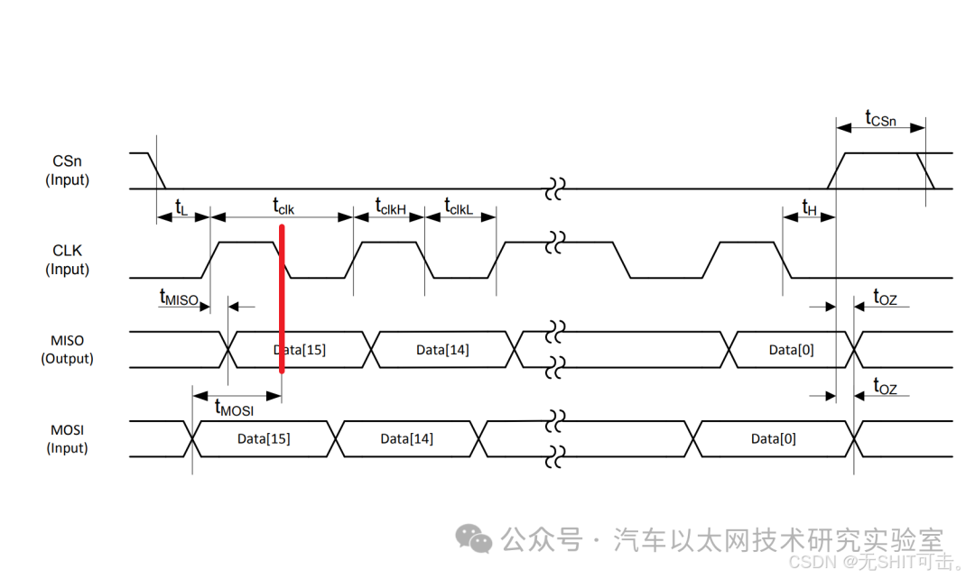
According to the AS5147P chip manual, set the clock polarity to 0, meaning the default state of the clock when idle is low, and set the clock phase to 1, meaning data is sampled on the second edge of the clock signal SCK. Therefore, the data sampling timing occurs on the falling edge of a waveform, as shown in the figure.
-
As shown in the figure, since 16 bits of data need to be sent, the data size is set to 16 bits. Additionally, since the data transmission order is most significant bit first, dataHeading is set to SpiIf_DataHeading_msbFirst.
-
As shown in the figure, due to specific timing requirements, set autoCS=0 to manually control the chip select signal in software. The code implementation will be provided in the subsequent transmission function.
-
The SPI communication frequency can be set as needed, limited by the maximum system clock frequency each system can provide and the maximum SPI transmission rate. Here, I set the baud rate to 800KHz.
3. Data Exchange
-
void transferData(void)
-
{
-
IfxPort_setPinModeOutput(CSPin, IfxPort_OutputMode_pushPull, IfxPort_OutputIdx_general);
-
IfxPort_setPinLow(CSPin);
-
uint32 ticks = IfxStm_getTicksFromMilliseconds(&MODULE_STM0, 10);
-
IfxStm_waitTicks(&MODULE_STM0, ticks);
-
g_qspi.spiBuffers.spiMasterTxBuffer[0] = 0xFFFF;
-
//g_qspi.spiBuffers.spiMasterTxBuffer[1] = 0xFF;
-
// for(int i = 0; i < 1; i++)
-
{
-
while(IfxQspi_SpiMaster_getStatus(&g_qspi.spiMasterChannel) == SpiIf_Status_busy);
-
IfxQspi_SpiMaster_exchange(&g_qspi.spiMasterChannel, &g_qspi.spiBuffers.spiMasterTxBuffer[0], &g_qspi.spiBuffers.spiSlaveRxBuffer[0], 1);
-
while(IfxQspi_SpiMaster_getStatus(&g_qspi.spiMasterChannel) == SpiIf_Status_busy);
-
}
-
IfxPort_setPinModeOutput(CSPin, IfxPort_OutputMode_pushPull, IfxPort_OutputIdx_general);
-
IfxPort_setPinHigh(CSPin);
-
//
-
// ticks = IfxStm_getTicksFromMilliseconds(&MODULE_STM0, 10);
-
// IfxStm_waitTicks(&MODULE_STM0, ticks);
-
}
Here, I used SPI communication to send 0xFFFF to the AS5047P encoder to obtain the absolute position information of the motor (I will write another article about obtaining position via SPI communication with the AS5047P encoder when I have time). The difference from the example is:
-
Before and after sending the information, I manually pulled the chip select signal high and low, pulling it low to start data transmission and high to end data transmission;
-
The first busy state waits for the SPI channel to be ready, and the second busy state waits for data transmission to complete;
-
Additionally, I modified the sending array spiBuffers.spiSlaveRxBuffer[0] from 8 bits to 16 bits, as well as the following exchange function:
1 IfxQspi_SpiMaster_exchange(&g_qspi.spiMasterChannel, &g_qspi.spiBuffers.spiMasterTxBuffer[0], &g_qspi.spiBuffers.spiSlaveRxBuffer[0], 1);
-
g_qspi.spiBuffers.spiMasterTxBuffer[0] points to the starting address of the sending buffer, indicating the data to be sent, while g_qspi.spiBuffers.spiSlaveRxBuffer[0] is a pointer to the receiving buffer, indicating where the received data will be stored. The last parameter 1 indicates the number of buffer arrays to send.
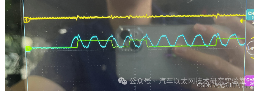
Ultimately, I successfully implemented SPI communication to obtain the motor position (all of this was achieved through research and continuous debugging, which was quite a journey). If anyone finds that SPI communication is not working, you might try my approach. Now, let’s take a look at the waveform I obtained, with the blue line representing the clock signal and the green line representing the MOSI signal:
Conclusion
The SPI configuration for the TC275 chip mainly involves some pin configurations and specific parameter settings related to SPI, such as chip select and clock parameters. The most critical aspect is to understand the logic of SPI communication implemented in the examples provided by the chip, which is the most important part. The pin configurations provide a good platform, but how to use it depends on your understanding of the function APIs.


*Disclaimer: This article is original or forwarded by the author. If it inadvertently infringes on any party’s intellectual property rights, please inform us for deletion.
The above images and text are sourced from the internet. If there is any infringement, please contact us promptly, and we will delete it within 24 hours.
The content of the article reflects the author’s personal views. The Automotive Ethernet Technology Research Laboratory reprints it solely to convey a different perspective and does not represent the laboratory’s endorsement or support of this view. If there are any objections, please feel free to contact the Automotive Ethernet Technology Research Laboratory.
Original link:
https://blog.csdn.net/westbrookd/article/details/139237125