
Click the blue text
Follow us
1. Clock Synchronization Issues in Serial Data
Sending serial data (such as USB, UART, I2C, SPI, etc.) is done over a single data bus. If a continuous stream of 01 signals is sent to the receiving device over this bus, the difference in clock frequencies between the sender and receiver raises synchronization issues. For example, if the receiver receives a continuous low signal, it cannot determine whether this represents three 0s or ten 0s.
2. Clock Synchronization of I2C and SPI Data
To solve the above problem, I2C and SPI transmit a clock signal alongside the data signal to synchronize data transmission on both ends. The receiver can sample data correctly with the help of the clock signal. For example, I2C uses SDA for data transmission and SCL for synchronization clock. This approach resolves the clock synchronization issue but requires an additional clock signal line.
3. Clock Synchronization of USB Data
USB data communication does not require an additional clock signal line to maintain synchronization; it uses NRZi (Non-Return-to-Zero Inverted Code) for data transmission. Before this, let’s explain what RZ (Return-Zero code) encoding is.In RZ encoding, a positive voltage represents logic 1, and a negative voltage represents logic 0. After transmitting each bit of data, the signal returns to 0 voltage, resulting in three voltage levels: positive, negative, and zero.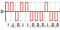 From the above diagram, the receiver only needs to sample the data after the signal returns to zero to obtain the actual data transmitted on the line. The advantage of this method is that it effectively embeds the clock signal within the data, achieving self-synchronization of the data. However, while it eliminates the clock line, it adds zero operations during actual data transmission, wasting half of the data bandwidth.Using Non-Return-to-Zero (NRZ) encoding removes the zero operations, effectively solving the bandwidth waste issue. However, as shown in the diagram below, while it resolves the bandwidth issue, the clock synchronization problem returns.
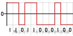 Similarly, USB uses NRZI encoding, where signal transitions represent a logic state. In USB transmission, a voltage change represents 0, while no change represents 1. The transitions can serve as a notification mechanism, and it can be seen that even if the NRZI waveform is completely inverted, the data sequence it represents remains unchanged, which is particularly convenient for signals transmitted via differential lines like USB. However, this encoding also has clock synchronization issues.In USB, a synchronization field can be used to address clock synchronization issues. Each USB data packet should ideally include a synchronization field, fixed at 0000 0001. After NRZI encoding, this becomes a square wave, allowing the receiver to determine the clock frequency of the data, enabling accurate data parsing.However, there remains a problem: while the receiver can actively match the frequency of the sender, there will always be some discrepancy between the two.If the data signal consists of 1000 logic 1s, after USB’s NRZI encoding, it results in a long period of unchanged voltage. In this case, even a thousandth difference in frequency between the receiver and sender can cause the data to be sampled as either 1001 or 999.USB addresses this issue by enforcing bit-stuffing, which involves inserting a 0 after every six consecutive 1s in the data being transmitted. This forces a signal transition, prompting the receiver to adjust its frequency. This ensures that logically, there is at least one voltage transition every seven bits, facilitating synchronization between data and clock. The receiver can then remove the 0 following the six consecutive 1s to restore the original data.
4. UART
UART is asynchronous communication, where data is transmitted character by character. The receiving device can correctly receive data as long as it remains synchronized with the sending device during the time taken to transmit a character, starting from the received start signal. The arrival of the start bit of the next character recalibrates the synchronization (achieved by detecting the start bit for self-synchronization of the sender and receiver’s clocks).UART Data Transmission Format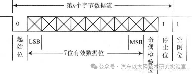 The meanings of each position are as follows:Start Bit: A logic