Author / Expert from Agricultural Bank of China Data Center Xu Qingbang
Senior Specialist from Agricultural Bank of China Data Center Li Yiyun
Several years ago, Agricultural Bank planned and built the VXLAN DCI (Datacenter Interconnect) network core at the head office level, interconnecting internal and external Fabric resource pools through DCI at high speed, and adopting original multi-segment VXLAN and two-level external network technology to achieve logical partitioning, resource scheduling, and service chain functions across Fabric, providing an ultra-large-scale network resource pool for cloud-native applications. This architecture has become the best practice and de facto standard for large financial data center networks, widely adopted by peers.
The VXLAN DCI initially mainly provided access to hard SDN Fabric resource pools, but in recent years, soft SDN technology has gradually been piloted and applied on a large scale in the financial industry. The VXLAN DCI architecture needs to accommodate the access requirements of soft SDN Fabric resource pools to achieve a unified architecture that integrates soft and hard SDN. This article focuses on the technical principles, network design, and integration methods with VXLAN DCI, using Huawei HCS8.1 cloud platform as a prototype.
Soft SDN Networking Structure
Soft and hard SDN are referred to as Host Overlay and Network Overlay, respectively, with the biggest difference in the position of the VxLAN gateway, as well as network services and operation and maintenance methods. The comparison is as follows.
The VXLAN gateway: the hard SDN gateway is located on the external access switch, which has high requirements for hardware MAC/ARP/FIB table entries, supports high-density line-speed forwarding, and generally requires homogeneous network devices within the Fabric; the soft SDN gateway is located on the internal vSwitch of the server, which has high requirements for software vSwitch Openflow table entries, consumes server CPU, memory, and other resources, has slightly weaker forwarding performance, and the hardware access switch is a pure Underlay device that does not perceive tenant and virtual machine information, allowing heterogeneous network devices within the Fabric.
Network services: hard SDN mainly provides L2/L3 connectivity, while higher-level services like FW and LB require dedicated software or hardware facilities, and also need to solve the adaptation problem between the controller and the cloud platform; soft SDN serves as an integrated component of the cloud platform, does not involve cloud-network docking issues, and can provide full-stack services from L2 to L7, including vFW, ELB, EIP, NAT, VPN, etc., all achieved through server software or NFV, possessing rapid delivery and horizontal expansion capabilities.
Operation and maintenance methods: hard SDN technology started earlier in the financial industry, where devices exchange MAC and IP routing information through BGP EVPN, inheriting the traditional routing and switching technology system. Network personnel can quickly get started with minimal training, and there are mature supporting visual intelligent operation and maintenance systems that make network status clear at a glance. Soft SDN originated in public cloud environments and has only gradually been deployed in the financial industry in the past year or two. The vSwitch encapsulates and forwards VXLAN packets based on the Openflow flow tables issued by the controller, which poses a significant challenge for network personnel accustomed to routing and switching, and there is a lack of a complete intelligent operation and maintenance system, making fault handling relatively difficult.
From the above comparison, it can be seen that while soft SDN is slightly deficient in forwarding performance and intelligent operation and maintenance, it leads in flexibility and scalability compared to hard SDN. With the advancement of the privatization of public cloud technology stacks, soft SDN is gradually being accepted and recognized by the industry and users.
A typical soft SDN Fabric consists of management areas, public service areas, network service areas, and business areas, interconnected through core switches, with a physical networking structure of SPINE+LEAF within each partition. The specific divisions are as follows:
Management area: Access area for Openstack control nodes, soft SDN controllers, cloud service components, etc.
Public service area: Access area for tenant DNS, public PaaS, API gateways, etc.
Network service area: Access area for VPC Router, ELB, EIP, NAT, VPN, and other soft network elements.
Business area: Access area for VM hosts, BM bare metal, storage, etc.
Soft SDN Technical Principles
Soft SDN simulates all network and security services through a unified server form, including basic L2/L3 connectivity, vFW, ELB, EIP, NAT, VPN, etc., meeting all the network service expectations of cloud users. Below, we introduce the most commonly used soft SDN technologies, network services, and basic principles in private clouds, with specific implementations illustrated in Figure 1.
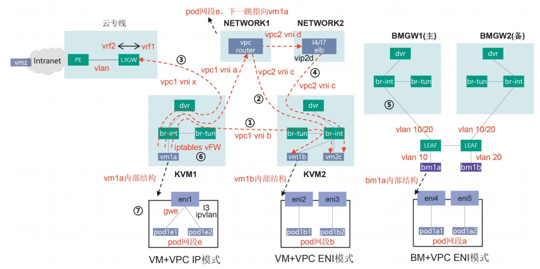
Figure 1 Network Service Diagram
(1) DVR (Distributed Virtual Router), similar to the distributed routing technology of hard SDN, mainly provides routing intercommunication within the VPC.
Assuming vm1a in segment a of vpc1 (host kvm1) accesses vm1b in segment b (host kvm2), kvm1 vm1a sends the packet via br-int to the dvr gwa gateway, dvr queries the flow table to modify the source MAC=gwb, destination MAC=vm1b, the packet then passes through the local br-int and br-tun, br-tun queries the flow table to modify the source MAC=dvr, and sends the packet through the VXLAN tunnel (vni=b) to kvm2. kvm2 br-tun receives the VXLAN packet, queries the flow table to strip the VXLAN encapsulation and map it to VLAN b, since the source MAC=dvr, it directly forwards the packet to br-int, finally reaching vm1b.
(2) VPC Router, provides routing intercommunication between VPCs based on DVR.
Assuming vm1a in segment a of vpc1 accesses vm2c in segment c of vpc2, a static cross-VPC route is configured on the VPC router, with vpc1 routing c pointing to vpc2 and vpc2 routing a pointing to vpc1. kvm1 vm1a sends the packet via br-int to the dvr gwa, dvr queries the flow table to modify the source MAC=gwa, destination MAC=vpcrouter, the packet then passes through the local br-int and br-tun, br-tun queries the flow table to modify the source MAC=dvr, and sends the packet through the VXLAN tunnel (vni=a) to the VPC router. The VPC router receives the VXLAN packet, queries the flow table to strip the VXLAN encapsulation and map it to vpc1, based on the destination address vm2c switches to vpc2, and finally sends the packet to vm2c using the VXLAN tunnel (vni=c).
The above describes the routing intercommunication process between different VPCs within the same Fabric. If vpc1 and vpc2 belong to Fabric1 and Fabric2 respectively, a VPC Peering needs to be established between the VPC Routers of the two Fabrics, and the Underlay routing must also be connected to achieve cross-Fabric VPC routing.
(3) Cloud Dedicated Line, all VPC virtual networks are built based on VXLAN within the Fabric or on the cloud, but ultimately they need to connect to the external world, serving users below the cloud. The device providing cloud dedicated line access is called L3GW (Layer 3 Gateway), generally a hard SDN switch. The soft SDN controller is responsible for establishing BGP EVPN neighbors with L3GW and converting Openflow flow tables with Type2/3/5 EVPN routes.
Assuming vm1a in segment a of vpc1 accesses vmz in segment z below the cloud, kvm1 vm1a sends the packet via br-int to dvr gwa, dvr queries the flow table to modify the source MAC=gwx, destination MAC=l3gw, the packet then passes through the local br-int and br-tun, br-tun queries the flow table to modify the source MAC=dvr, and sends the packet through the VXLAN tunnel (vni=x) to l3gw. l3gw receives the VXLAN packet, strips the VXLAN encapsulation and maps it to vpc1 vrf1, queries the vmz route pointing to the cloud dedicated line vrf2, and then sends the packet to the external PE, ultimately routing it to vmz through the external cloud network.
The above describes the hard dedicated line based on L3GW, and a soft dedicated line can also be provided by the VPC Router to connect to the network below the cloud. From a performance perspective, the hard dedicated line is preferred.
(4) ELB, provides L4 and L7 load balancing services for computing resources.
Assuming vm1a in segment a of vpc1 acts as a client accessing the service address vip2d in segment d of vpc2, with the backend server being vm2c in segment c of vpc2, a static cross-VPC route is configured on the VPC router, with vpc1 routing c+d pointing to vpc2, and vpc2 routing a pointing to vpc1. kvm1 vm1a sends the packet to the VPC router, which queries the flow table to forward it to vip2d of vpc2, the ELB receives it and schedules it to server vm2c, while the soft SDN controller also issues the return flow table to kvm2 br-int to ensure consistent return paths.
In actual networking, more often than not, internal network clients below the cloud access the cloud dedicated line, while public clients access the cloud ELB VIP via the internet + EIP, with the ELB scheduling process as described above.
(5) BM GW, provides network access for BM bare metal.
LEAF switches connect BM through Access ports, assigning a unique VLAN ID to each BM, and connecting BM GW through Trunk ports, allowing all BM VLANs to pass through, logically equivalent to BM directly connecting to the internal br-int of BMGW, accessing the shared VPC plane with VMs. In specific implementations, since LEAF is a hardware switch, the soft SDN controller needs to manage the LEAF switch ports through Neutron+.
Assuming bm1a in segment a of vpc1 accesses bm1b in segment b, the access process is similar to that of VMs and will not be elaborated further.
(6) Other services: vFW is implemented based on the iptables mechanism of the compute node host, belonging to a distributed cloud FW, which can meet most VPC protection needs, but the policy specifications of vFW are significantly lower than those of hardware FW. For large VPCs, using external hardware FW is a good option. Other services like EIP, NAT, VPN, etc., are more related to internet access and will not be introduced one by one.
(7) Container networks: HCS8.1 is an integrated cloud platform for IaaS + PaaS, capable of providing polymorphic computing resources including BM/VM/Pod, as well as mainstream integrated network access methods such as VPC IP and VPC ENI (Elastic Network Interface), with specific examples as follows.
VPC IP mode: The cloud platform creates eni1 elastic network card in vpc1, binds it to vm1a, and assigns an address in segment a. The internal vm1a adopts l3 ipvlan cni, eni1 serves as the parent interface, providing network access for pod1e1 and pod1e2 through sub-interfaces, with pods assigned unique segment e addresses. A route for segment e needs to be configured on the VPC router, pointing to vm1a, to achieve routing intercommunication between the VPC network plane and pod network plane.
VPC ENI mode: The cloud platform creates eni2 and eni3 elastic network cards in vpc1 and binds them to pod1b1 and pod1b2 in vm1b, assigning addresses in segment b. It also creates eni4 and eni5 elastic network cards and binds them to pod1a1 and pod1a2 in bm1a, assigning addresses in segment a, achieving direct connection of pods to the VPC network plane. There are specifications limits when using eni, and Huawei has adopted a unique eni+vlan technology, cleverly solving the eni upper limit issue.
Soft SDN Network Design
After introducing the technical principles of soft SDN, the next step is to combine these technologies to construct a general soft SDN Fabric and integrate it into the VXLAN DCI network, with specific networking illustrated in Figure 2.
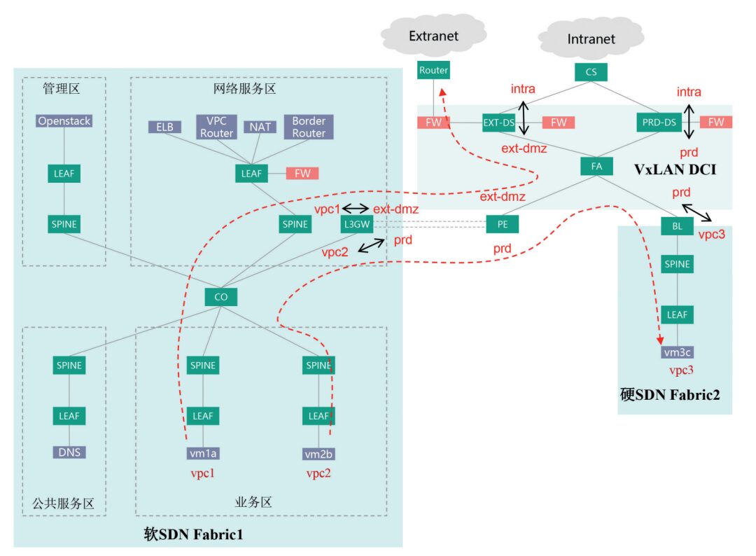
Figure 2 Comprehensive Networking Diagram
Soft SDN Fabric1 adopts a standard four-functional area architecture, supporting access for over 2000 physical servers, creating external DMZ area vpc1 and internal production area vpc2 in the cloud, connected to DCI PE through their respective cloud dedicated lines, binding vpc1 to extdmz dci vpn and vpc2 to prd dci vpn on the L3GW, bridging the cloud VPC and dci vpn routes, where dci vpn represents logical partitions or security domains.
Hard SDN Fabric2 adopts the BL+SPINE+LEAF standard architecture, creating internal production area vpc3 in the cloud, connecting DCI core through the boundary BL, and binding vpc3 to prd dci vpn on the BL, bridging the cloud VPC and dci vpn routes. Since vpc1 and vpc3 are bound to the same prd dci vpn, this naturally achieves direct routing between the two internal production partitions.
PRD-DS serves as the network boundary between cloud prd dci vpn and cloud under intra vpn, with hardware FW deployed alongside to ensure strict control of mutual access between cloud and external. At the same time, considering the specification limitations of vFW in soft SDN Fabric, vpc2 does not enable vFW internally, but instead uses the FW of PRD-DS to provide boundary protection for both vpc2 and vpc3.
EXT-DS serves as the network boundary between cloud ext-dmz dci vpn, cloud under intra vpn, and external networks, with internal and external hardware FW deployed alongside, forming a standard two-firewall DMZ network structure. vpc1 internally does not enable vFW, and the FW directly connected to EXT-DS provides internal and external boundary protection for vpc1.
Taking the mutual access between vpc1 and vpc2 as an example, since neither vpc1 nor vpc2 has enabled vFW, they cannot use VPC peering to directly bridge the two VPC routes in the cloud. Instead, they rely on the service chain capabilities provided by DCI and boundary FW to ensure that the access path passes through their respective boundary FW, achieving a unified entry point and security protection for cloud and external access.
Conclusion and Outlook
Although soft SDN technology is flexible and offers rich services, improvements are still needed in forwarding performance and network operation and maintenance. The ultimate means of performance enhancement is through intelligent network card technology, also known as elastic bare metal, which offloads the Hypervisor and VXLAN gateway functions to hardware network cards, preserving the flexibility of soft SDN while achieving performance levels comparable to hard SDN, albeit at a relatively high cost. Hard SDN still has obvious advantages in specific scenarios, such as distributed databases and big data, where extreme performance is pursued, requiring cloud platforms to provide physical server resources and networks to offer high-speed forwarding capabilities, with relatively less reliance on other network services. Hard SDN can effectively address these pain points. It can be anticipated that soft and hard SDN will coexist for a long time to leverage their respective advantages. In specific implementations, soft and hard switches can be constructed independently or jointly to form a Fabric, the latter being referred to as Hybrid Overlay, requiring the controller to manage both soft and hard switches and protocol conversions to meet the network access needs of virtual machines and bare metal.
(Column Editor: Zhang Lixia)
(Click to view exciting content)
● Case Study: ICBC DevOps Transformation Practice
● Case Study: Thoughts on Risk Prevention Strategies for Grassroots Network Operations
● Case Study: Empowering Cross-border Blockchain Platforms, Renewing Export Credit Insurance Financing
● Case Study: Design and Planning of Zero Trust Architecture for Provincial Agricultural Credit Internet Finance
● Case Study: Building a Deep Defense System, Strengthening Network Security Protection


New Media Center: Director / Kuang Yuan Editor / Fu Tiantian Zhang Jun Tai Siqi