
Project Components
-
Hardware
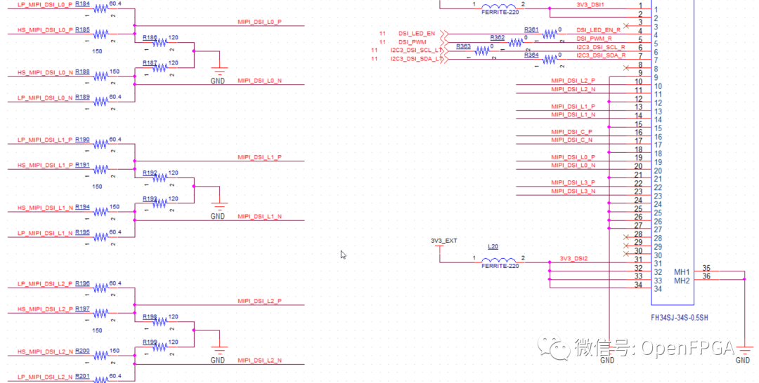
Spartan-7 SP701 FPGA with MIPI interface implemented using resistor network
OV5640 MIPI interface
-
Software
AMD Vivado version 2020 or above
AMD Vitis 2020
Introduction
MIPI interface is very popular now, and domestic FPGAs generally come with MIPI interfaces. AMD-Xilinx started supporting MIPI levels from the U+ series. From the usage in China, the Spartan-7 FPGA is the most widely used device, so this example uses the Spartan-7 FPGA to implement MIPI levels using a resistor network. For specific hardware solutions, see:
Xilinx FPGA MIPI Interface Simple Explanation
Setting Up the Project
For this project, it is recommended to use Vivado version 2020 or above, as MIPI IP is now free.
Step 1: Create a Vivado Project
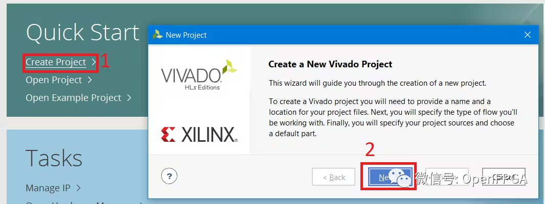
Run Vivado
(1) “Create Project” –> (2) Click “Next”
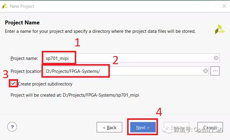
Specify (1) “Project Name” –> (2) Specify Project Directory –> (3) Set Checkboxes –> (4) Click “Next”
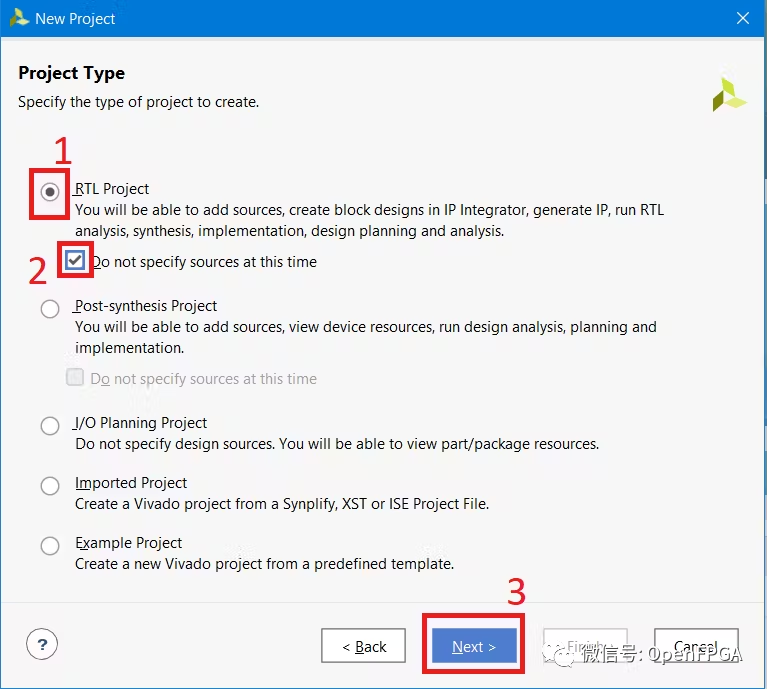
(1) Select Project Type –> (2) Set Checkboxes –> (3) Click “Next”
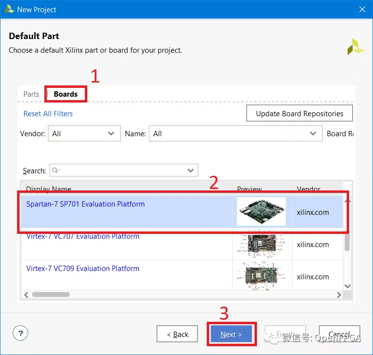
(1) Select the “Boards” tab –> (2) Find and select SP701 –> (3) Click “Next”
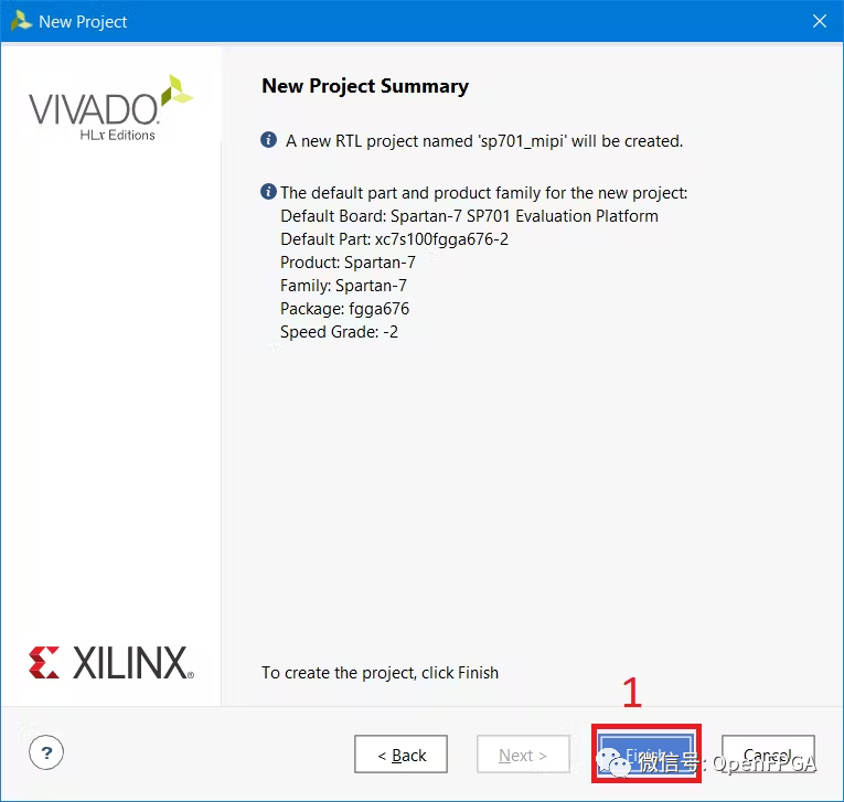
(1) Click “Finish”
Step 2: Generate Example Design
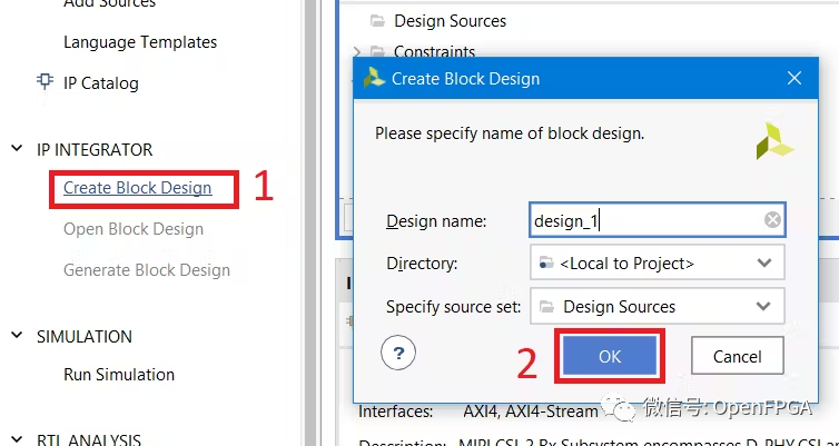
In Vivado, (1) “Create Block Design” –> (2) Click “OK”
(1) Click “+” or “Ctrl+I” –> (2) Type “mipi” in “Search” –> (3) Double-click “MIPI CSI-2 Rx Subsystem” IP core
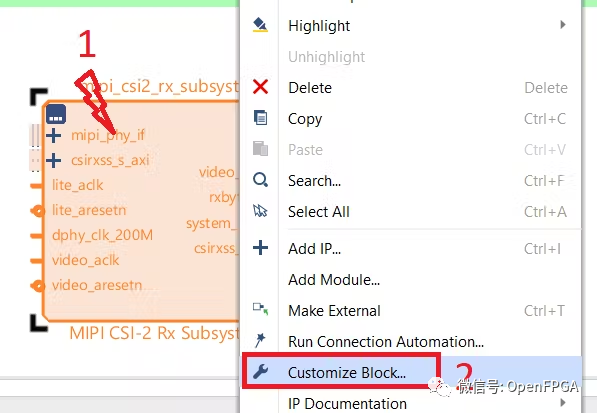
(1) Right-click on IP –> (2) Select “Customize Block”
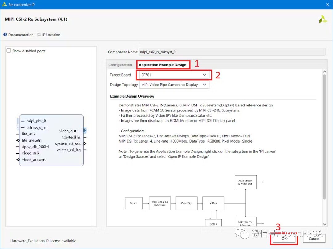
(1) Open the “Application Example Design” tab –> (2) Select “SP701” –> (3) Click “OK”
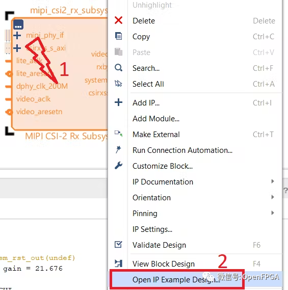
(1) Right-click on IP –> (2) Select “Open Example Design”
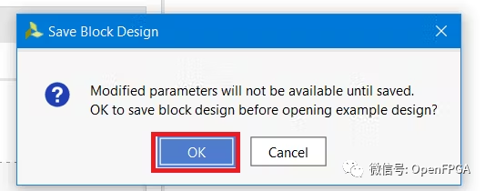
Click “OK” to save design changes
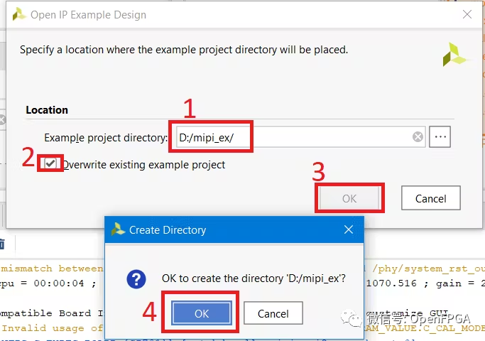
(1) Specify the directory for the example project (Note: Path on Windows must be as short as possible) –> (2) Set Checkboxes –> (3) Click “OK” –> (4) Click “OK”
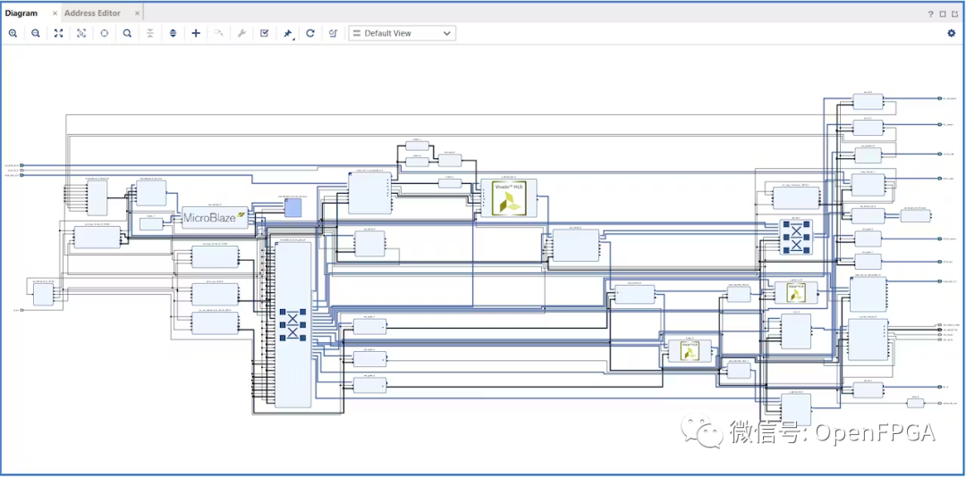
The example project will open in a new Vivado window. Wait a few minutes for the project to build.
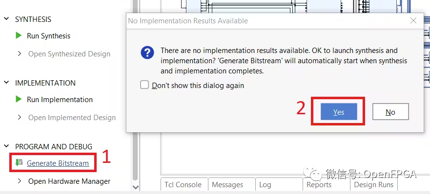
In the example project Vivado, (1) “Generate Bitstream” –> (2) Click “YES”
Wait for the bitstream to generate
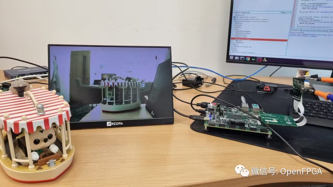
Step 3: Hardware Testing
Connect the OV5640 sensor to the MIPI CSI interface on the FPGA board. Connect an HDMI display or MIPI display to the development board.
Step 4: Running Debugging
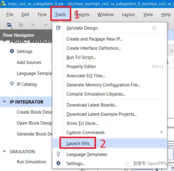
Open VITIS software from Vivado. (1) “Tools” –> (2) “Launch VITIS”
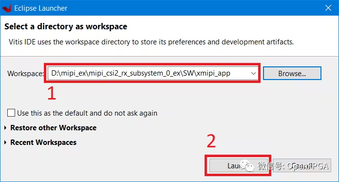
(1) Specify workspace (Select the provided mipi_csi2_rx_subsystem_0_ex :: SW :: xmipi_app) –> (2) “Launch”
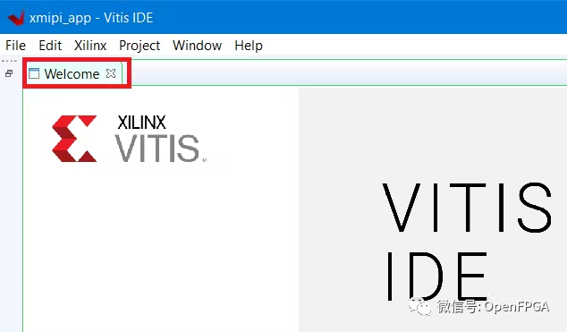
Close the VITIS “Welcome” tab
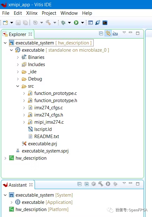
Now you will see the software part of the project. Code for the MicroBlaze soft processor.
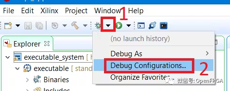
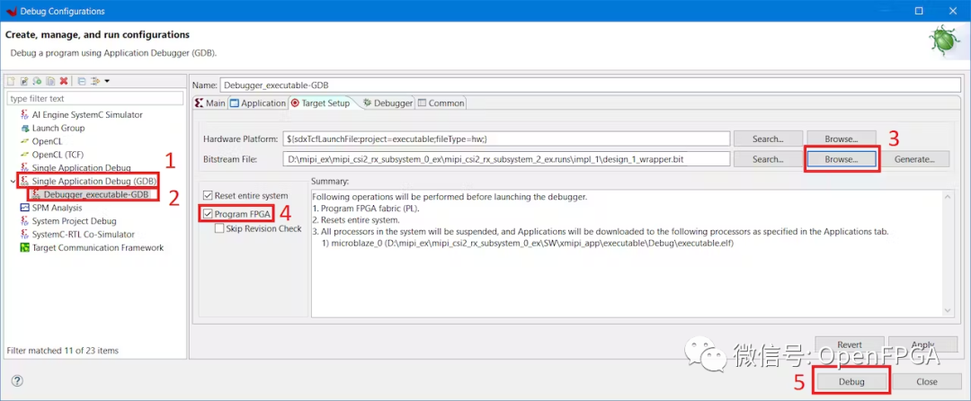
(1) Follow the arrow –> (2) Click “Debug Configurations”
(1) Double-click “Single Application Debug (GDB)” –> (2) Select “Debugger Executable” –> (3) Specify the bitstream.bit file generated by Vivado –> (4) Set Checkbox –> (5) Click “Debug”
Press the run button and follow the messages on the serial terminal

Conclusion
Generating an example project for the MIPI interface on the FPGA board from Vivado is very simple.
❝
https://www.xilinx.com/products/boards-and-kits/sp701.html#resources
❞