Follow+Top Public Account, don’t miss out on exciting content

Materials Needed
-
PCB -
ESP8266 or NodeMCU -
Jumper wires -
Soldering tools
Step 1: Preparation

Step 2: Create a 7-segment display using Neo Pixel LED


<span>DOUT</span> to the second panel’s<span>DIN</span>.Step 3: Connect the dashboard


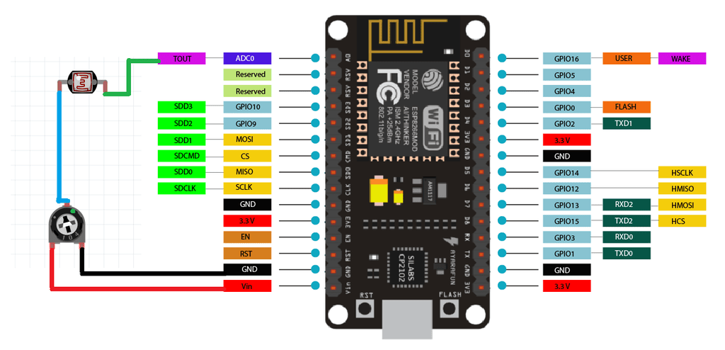
<span>Dash</span>, which contains 2 LEDs as binary digits that light up once every second.Step 4: Introduction to NodeMCU/ESP8266

Step 5: Supported functions in the code

-
Temperature and humidity display using tactile switch
-
Brightness control using LDR sensor on pin A0
Step 6: Video demonstration
Step 7: 7-segment clock

Step 8: Code
-
First, use libraries to initialize the code:
#include <ESP8266WiFi.h>
#include <Adafruit_NeoPixel.h>
#include <WiFiUdp.h>
#include <NTPClient.h>
#include <TimeLib.h>
#include <DHT.h>
#include <Adafruit_Sensor.h>
-
Define all pixels, I/O pins, and sensor pins:
#define PIXEL_PER_SEGMENT 2 // Number of LEDs in each Segment
#define PIXEL_DIGITS 4 // Number of connected Digits
#define PIXEL_PIN 2 // GPIO Pin
#define PIXEL_DASH 1 // Binary segment
#define LDR_PIN A0 // LDR pin
#define DHT_PIN 13 // DHT Sensor pin
#define BUTTON_PIN 12 // Button pin
3. For time format, connect ESP8266 to the internet via Wi-Fi:
WiFi.begin(ssid, password);
Serial.print("Connecting.");
while ( WiFi.status() != WL_CONNECTED )
-
Time setting:
void disp_Time() {
clearDisplay();
writeDigit(0, Hour / 10);
writeDigit(1, Hour % 10);
writeDigit(2, Minute / 10);
writeDigit(3, Minute % 10);
writeDigit(4, Second / 10);
writeDigit(5, Second % 10);
disp_Dash();
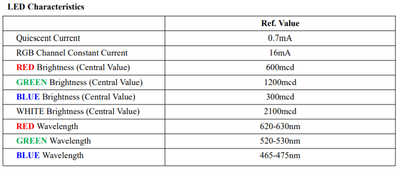
5. Color settings on the panel:
if (index == 0 || index == 1 ) color = strip.Color(0, Brightness, 0);
if (index == 2 || index == 3 ) color = strip.Color(0, Brightness, 0);
if (index == 4 || index == 5 ) color = strip.Color(Brightness, 0, 0);
Step 9: Complete code
#include <ESP8266WiFi.h>
#include <Adafruit_NeoPixel.h>
#include <WiFiUdp.h>
#include <NTPClient.h>
#include <TimeLib.h>
#include <DHT.h>
#include <Adafruit_Sensor.h>

#define PIXEL_PER_SEGMENT  2     // Number of LEDs in each Segment
#define PIXEL_DIGITS       4     // Number of connected Digits
#define PIXEL_PIN          2     // GPIO Pin
#define PIXEL_DASH         1    // Binary segment

#define LDR_PIN       A0    // LDR pin
#define DHT_PIN       13    // DHT Sensor pin
#define BUTTON_PIN    12    // Button pin

// Uncomment the type of sensor in use
#define DHT_TYPE    DHT11     // DHT 11
//#define DHT_TYPE    DHT22     // DHT 22 (AM2302)
//#define DHT_TYPE    DHT21     // DHT 21 (AM2301)

#define TIME_FORMAT        12    // 12 = 12 hours format || 24 = 24 hours format

Adafruit_NeoPixel strip = Adafruit_NeoPixel((PIXEL_PER_SEGMENT * 7 * PIXEL_DIGITS) + (PIXEL_DASH * 2), PIXEL_PIN, NEO_GRB + NEO_KHZ800);
DHT dht(DHT_PIN, DHT_TYPE);

// set Wi-Fi SSID and password
const char *ssid     = "Hackster";
const char *password = "Sainisagar7294";

WiFiUDP ntpUDP;
// 'time.nist.gov' is used (default server) with +1 hour offset (3600 seconds) 60 seconds (60000 milliseconds) update interval
NTPClient timeClient(ntpUDP, "time.nist.gov", 19800, 60000); //GMT+5:30 : 5*3600+30*60=19800

int period = 2000;   //Update frequency
unsigned long time_now = 0;
int Second, Minute, Hour;

// set default brightness
int Brightness = 40;
// current temperature, updated in loop()
int Temperature;

bool Show_Temp = false;

//Digits array
byte digits[12] = {
  //abcdefg
  0b1111110,     // 0
  0b0110000,     // 1
  0b1101101,     // 2
  0b1111001,     // 3
  0b0110011,     // 4
  0b1011011,     // 5
  0b1011111,     // 6
  0b1110000,     // 7
  0b1111111,     // 8
  0b1110011,      // 9
  0b1001110,     // C
  0b1000111,     // F
};

//Clear all the Pixels
void clearDisplay() {
  for (int i = 0; i < strip.numPixels(); i++) {
    strip.setPixelColor(i, strip.Color(0, 0, 0));
  }
  strip.show();
}

void setup() {
  Serial.begin(115200);
  strip.begin();
  strip.show();

  dht.begin();
  pinMode(BUTTON_PIN, INPUT);

  WiFi.begin(ssid, password);
  Serial.print("Connecting.");
  while ( WiFi.status() != WL_CONNECTED ) {
    delay(500);
    Serial.print(".");
  }
  Serial.println("connected");
  timeClient.begin();
  delay(10);
}

void loop() {
  if (WiFi.status() == WL_CONNECTED) { // check WiFi connection status
    int sensor_val = analogRead(LDR_PIN);
    Brightness =40;
    timeClient.update();
    int Hours;
    unsigned long unix_epoch = timeClient.getEpochTime();   // get UNIX Epoch time
    Second = second(unix_epoch);                            // get seconds
    Minute = minute(unix_epoch);                            // get minutes
    Hours  = hour(unix_epoch);                              // get hours

    if (TIME_FORMAT == 12) {
      if (Hours > 12) {
        Hour = Hours - 12;
      }
      else
        Hour = Hours;
    }
    else
      Hour = Hours;
  }

  if (digitalRead(BUTTON_PIN) == LOW) {
    Show_Temp = true;
  }
  else
    Show_Temp = false;

  if (Show_Temp) {
    Temperature = dht.readTemperature();
    Serial.println(Temperature);
    clearDisplay();
    writeDigit(0, Temperature / 10);
    writeDigit(1, Temperature % 10);
    writeDigit(2, 10);
    strip.setPixelColor(28, strip.Color(Brightness, Brightness,  Brightness));
    strip.show();
    delay(3000);
    clearDisplay();
    Show_Temp = false;
  }
  while (millis() > time_now + period) {
    time_now = millis();
    disp_Time();     // Show Time
  }
}

void disp_Time() {
  clearDisplay();
  writeDigit(0, Hour / 10);
  writeDigit(1, Hour % 10);
  writeDigit(2, Minute / 10);
  writeDigit(3, Minute % 10);
  writeDigit(4, Second / 10);
  writeDigit(5, Second % 10);
  disp_Dash();
  strip.show();
}

void disp_Dash() {
  int dot, dash;
  for (int i = 0; i < 2; i++) {
    dot = 2 * (PIXEL_PER_SEGMENT * 7) + i;
    for (int j = 0; j < PIXEL_DASH; j++) {
      dash = dot + j * (2 * (PIXEL_PER_SEGMENT * 7) + 2);
      Second % 2 == 0 ? strip.setPixelColor(dash, strip.Color(0,Brightness ,0)) : strip.setPixelColor(dash, strip.Color(0, Brightness,0));
    }
  }
}

void writeDigit(int index, int val) {
  byte digit = digits[val];
  int margin;
  if (index == 0 || index == 1 ) margin = 0;
  if (index == 2 || index == 3 ) margin = 1;
  if (index == 4 || index == 5 ) margin = 2;
  for (int i = 6; i >= 0; i--) {
    int offset = index * (PIXEL_PER_SEGMENT * 7) + i * PIXEL_PER_SEGMENT + margin * 2;
    uint32_t color;
    if (digit & 0x01 != 0) {
      if (index == 0 || index == 1 ) color = strip.Color(Brightness, 0,  Brightness);
      if (index == 2 || index == 3 ) color = strip.Color(Brightness, 0,Brightness);
      if (index == 4 || index == 5 ) color = strip.Color(Brightness, 0,  0);
    }
    else
      color = strip.Color(0, 0, 0);

    for (int j = offset; j < offset + PIXEL_PER_SEGMENT; j++) {
      strip.setPixelColor(j, color);
    }
    digit = digit >> 1;
  }
}
Step 10: Complete circuit diagram


Step 11: PCB Design (Panel part)

Main PCB design for displaying numbers and other letters.
Step 12: PCB Design (Dash part)


Step 13: Troubleshooting
-
<span>DIN</span>must always be connected in series with<span>DOUT</span>; if connected incorrectly or disconnected from anywhere, the entire device will stop working; -
Connect the Dash as shown above;
-
Ensure all connections are soldered well; poor soldering can lead to data value and color changes;
-
When soldering, do not heat the printed circuit board too much; keep the temperature below 300 degrees.
Step 14: Complete showcase


Hope you all enjoy this project!
Click the public account below and reply with the keyword “020” to get the relevant source files and high-definition images
Original link: https://www.instructables.com/RGB-7-Segment-Clock-Using-ESP8266/
Original author: sainisagar7294 Translated first published in:DF Maker Community