Before measuring circuits with a multimeter, understand 5 basic circuit concepts.
■ Circuit: Also called a loop, it refers to a closed circuit that runs from one end of the power source through the load and finally returns to the other end of the power source.

■ Open Circuit: Also called a break circuit, when the switch is open, the power source does not form a loop, and the current in the circuit is zero.

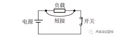
■ Short Circuit: The load is directly shorted by a wire or the load is internally damaged, causing the charge to bypass the load and go directly from the positive to the negative terminal, resulting in maximum current flowing through the circuit.
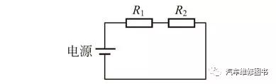
■ Series Connection: Several components are connected end to end in the circuit, allowing current to flow through only one path. This connection method is called series connection, as shown in the series circuit of resistors R1 and R2.
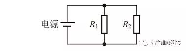
■ Parallel Connection: Several components are connected head to head and tail to tail, all connected to a power source. This connection method is called parallel connection, as shown in the parallel circuit of resistors R1 and R2.

1. Measure Open Circuit – Voltage Detection Method
Set the multimeter to the voltage range. All live wires can be checked and diagnosed using the method below.
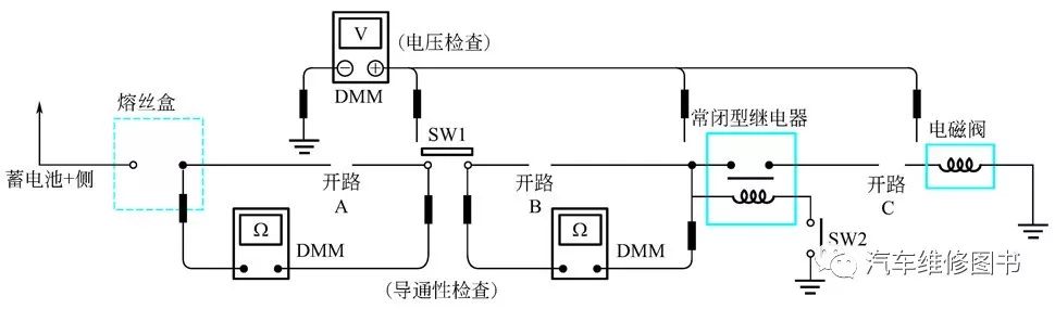
Operation Diagram:
① Connect one probe of the multimeter to a known good ground.
② Start testing from one end of the circuit to the other.
③ Disconnect switch SW1 and measure the voltage at the switch SW1. If there is voltage, the open circuit is further away from SW1; if there is no voltage, the open circuit is between the fuse box and SW1 (Point A).
④ Close SW1 and test at the relay. If there is voltage, the open circuit is further away from the relay; if there is no voltage, the open circuit is between SW1 and the relay (Point B).
⑤ Close the relay and test at the solenoid valve. If there is voltage, the open circuit is further away from the solenoid valve; if there is no voltage, the open circuit is between the solenoid valve and the relay (Point C).
2. Measure Open Circuit – Continuity Detection Method
Set the multimeter to the resistance range. All live wires can be checked and diagnosed using the method below.
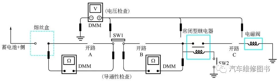
Operation Diagram:
① Disconnect the negative cable of the battery.
② Start testing from one end of the line to the other (e.g., the fuse device in the diagram).
③ Connect one probe of the multimeter to the fuse port on the load side.
④ Connect the other probe to the SW1 fuse box (power source) side (Point A). A low resistance value or zero indicates that this segment of the circuit is conducting well. If the circuit is open, the multimeter will indicate overload or a resistance of ∞ (infinity).
⑤ Connect the probes between SW1 and the relay (Point B). A low resistance value or zero indicates that this segment of the circuit is conducting well. If the circuit is open, the multimeter will indicate overload or infinite resistance.
⑥ Connect the probes between the relay and the solenoid valve (Point C). A low resistance value or zero indicates that this segment of the circuit is conducting well. If the circuit is open, the multimeter will indicate overload or infinite resistance. Any circuit can be checked using the above methods.
3. Measure Short Circuit – Voltage Detection Method
① Remove the burnt fuse and disconnect all loads powered through the fuse (i.e., disconnect SW1, relay, and solenoid valve).
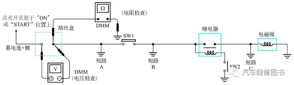
② Turn the ignition switch to the ON or START position. Confirm battery voltage at the fuse port on the positive side of the battery (one probe at the fuse box battery positive port, another probe at a known good ground).
③ Disconnect SW1 and measure the voltage across the two ports of the fuse with the multimeter probes. If there is voltage, the short circuit is between the fuse box and SW1 (Point A); if there is no voltage, the short circuit is further away from SW1.
④ Close SW1, disconnect the relay and solenoid valve, and measure the voltage across the fuse port with the multimeter probes. If there is voltage, the short circuit is between SW1 and the relay (Point B); if there is no voltage, the short circuit is further away from the relay.
⑤ Close SW1 and use a jumper with a fuse to connect the relay to measure voltage. If there is voltage, the short circuit is after the relay line or between the relay and the disconnected solenoid valve (Point C); if there is no voltage, return to check the power supply of the fuse box.
4. Measure Short Circuit – Continuity Detection Method
① Disconnect the negative battery terminal and remove the blown fuse.
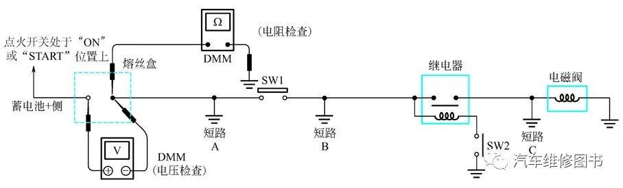
② Disconnect all loads powered through the fuse (disconnect SW1, relay, and solenoid valve).
③ Connect one probe of the ohmmeter to the load side of the fuse port and the other probe to a known good ground.
④ Disconnect SW1 and check for continuity. If there is continuity, the short circuit is between the fuse and SW1 (Point A); if there is no continuity, the short circuit is further away from SW1.
⑤ Close SW1 and then disconnect the relay. Place the probe on the load side of the fuse port and the known good ground. Then check for continuity. If there is continuity, the short circuit is between SW1 and the relay (Point B); if there is no continuity, the short circuit is further away from the relay.
⑥ Close SW1 and use a jumper to connect the relay. Place the probe on the load side of the fuse port and the known good ground. Then check for continuity. If there is continuity, the short circuit is between the relay and the solenoid valve (Point C); if there is no continuity, check the solenoid valve.
How to Use a Multimeter to Diagnose Circuits
In most cases, it is difficult to identify fault points in the electrical system just by visual inspection, so it is very important to understand the circuit’s voltage to find faults. The following illustrations demonstrate the measurements made with a multimeter.
Normal Circuit When the Switch is Open ▼
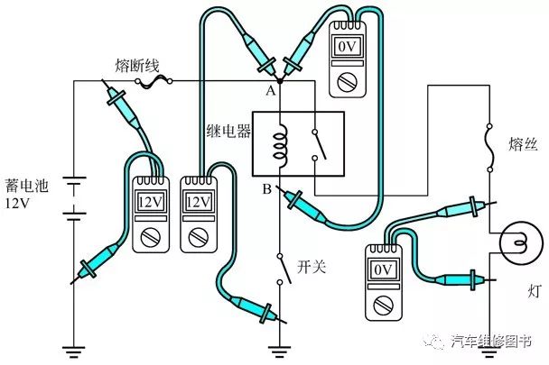
Normal Circuit When the Switch is Closed ▼
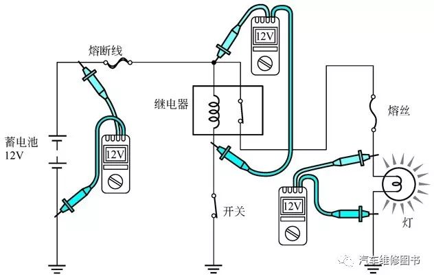
Circuit Performance When There is Poor Contact ▼
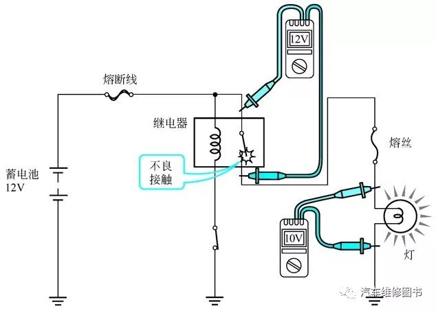
Determine Fault Location Based on Measurement Results ▼
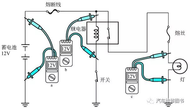
If the headlights are not on, then based on the measurement conditions shown above, the fault point can be determined.
Content Source
“Automotive Repair Skills Hands-On Learning”
Author: N.J. Yixiu, Price: 78 Yuan
This book infiltrates important repair details through hands-on operation, using “learning diagrams” and “operation diagrams” throughout the book. The combination of images and text can illustrate problems as much as possible, simplifying the text content. Through concise language and charts, it presents automotive repair knowledge and practical skills to the reader, striving to achieve immediate learning and application.
To purchase this book, please visit Dangdang, JD, or Tmall, or click the bottom “Read Original” to order with one click.