Based on Symphony Plus Fieldbus Network Auxiliary Control System of Power Plant
Zhao Xia Zhang Ran Tian Hongzhe
(Beijing Automatic Control Technology Department, Xi’an Thermal Power Research Institute Co., Ltd., Changping District, Beijing 102209)
Abstract:The Symphony Plus system is a new generation product launched by ABB, with the most prominent feature being its support for Profibus bus protocol. This paper takes the Huaneng Sunshine Thermal Power Auxiliary Control Network control system as an example to introduce the key points of network planning and design for fieldbus devices under the ABB Symphony Plus system, and proposes solutions to common problems encountered during debugging.
Keywords:Symphony Plus system, fieldbus,Profibus bus, auxiliary control system
The balance of plant basedd on Profibus bus technology of
Symphony Plus system
Abstract: Symphony Plus system is the new generation products of ABB GROUP. And supporting Profibus bus protocol is one of its characteristics. Combining with the balance of plant in Huaneng Luoyang Thermal Power plant, the key points of network design of fieldbus devices in the ABB Symphony Plus System are introduced in this paper. And solutions are given to solve the problems during debugging the control system.
Key words: Symphony Plus System, fieldbus, Profibus bus, the balance of plant
0. Introduction
With the development of science and technology, achieving intelligent control and management in industrial production has become a trend. The DCS control system supporting fieldbus protocols provides a digital control platform for power plants, combined with intelligent digital instruments and equipment, improving the efficiency of power plant control systems, and reducing the comprehensive costs of design, construction, debugging, operation, maintenance, and system expansion.[1].
This paper introduces the design points and common problem solutions of the auxiliary control system of power plants based on the ABB Symphony Plus system fieldbus network, combined with the Huaneng Luoyang Thermal Power auxiliary control system.
1. Symphony Plus System
Symphony Plus system, abbreviated asS+ system, is ABB company’s Symphony Harmony and Melody series latest generation product. The Symphony Plus system includes a complete set of standard control software products and supporting hardware products to meet various needs of industrial automation.S+ controllerHPC800 is the latest representative of the Symphony Plus controller family.S+ control system’s most prominent feature is that thePDP800 PROFIBUS interface module supports Profibus protocol bus, realizing the connection between HPC800 controller and field devices, and it can easily integrateS+Turbine DIN module,S800 I/O, intelligent devices (such as smart transmitters, actuators, and smart electrical devices). One HPC800 can connect up to 8 redundantPDP800.
2. S+ System Fieldbus Device Network Planning
In the auxiliary control system of the power plant based on the S+ system fieldbus network, device signals mostly use Profibus-DP or Profibus- PA protocol bus transmission. Compared with traditional hard-wired signal transmission, the communication cables are greatly reduced, thus the planning of the bus network and the division of network segments are particularly important.
2.1 Bus Network Topology Design
When using fieldbus to transmit information, the length of the network segment and the number of connected devices have a significant impact on communication speed. Therefore, the topology structure of the network segment and the number of connected intelligent devices should be designed reasonably to ensure communication real-time performance.
Profibus protocol bus is divided into Profibus-DP and Profibus-PA. Among them, the transmission rate of Profibus-DP protocol bus is 0.0096~12Mbit/s, and the corresponding transmission distance is 100-1200m; without using a repeater, it can connect up to 31 slave devices (or fieldbus devices).Profibus-PA has a transmission rate of 31.25Kbit/s, and the corresponding transmission distance is 1900m, and can connect up to 32 fieldbus devices, but it cannot be directly connected to the master communication station, and can only be connected through DP/PA-LINK as a slave device (branch) of the Profibus-DP network segment. When designing the network segment, the number of slave devices connected to the Profibus-DP protocol bus should not exceed 16, and the number of intelligent devices connected to the Profibus-PA protocol bus should not exceed 12. Since Profibus-PA protocol bus uses bus power supply, the power supply voltage and current limits also need to be considered during specific project design[2-3].
S+ control system only supports Profibus protocol bus. Based on the above network segment topology design principles, and considering factors such as signal interference and system stability in practical applications, in the bus network design of the Huaneng Luoyang Thermal Power auxiliary control system, each pair ofPDP bus modules can carry a maximum of 12 DP redundant devices, 12 DP non-redundant devices, with a segment distance not exceeding 400m; each pair ofPDP bus modules can carry 2 PA segments through DP/PA couplers, with each PA segment carrying a maximum of 8 PA devices, with a segment distance not exceeding 1000m, and the total number of bus devices carried by a pair ofPDP bus modules (including DP bus devices and PA bus devices) should not exceed 48.
S+ system, a typical bus network diagram is shown in Figure 1:
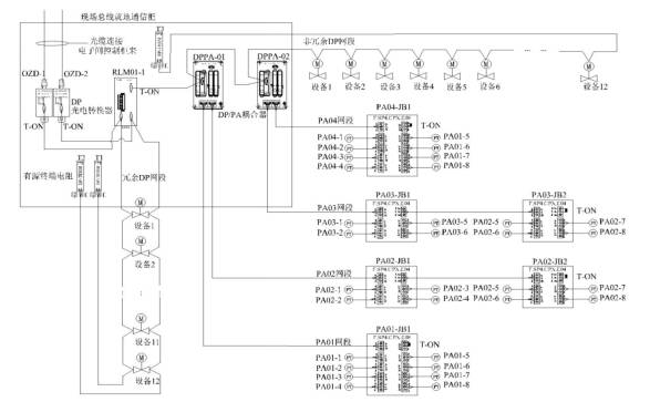
Figure 1 Typical S+ system bus network diagram
2.2 Fieldbus Device Segment Allocation Principles
Considering system stability and the convenience of maintenance and repair after system commissioning, when dividing fieldbus device segments, the following allocation principles should be followed: (1) The hard-wired signals and bus signals of the same master device should be divided under the same controller as much as possible to reduce communication between controllers; (2) Different intelligent devices detecting the same process parameters should be connected to different fieldbus branches; (3) More than two (including two) identical function intelligent devices should be connected in different segments, for example, motor protection devices that serve as backups; (4) Different parameters of intelligent instruments for detecting the same object should be connected on the same segment, for example, pressure, flow, conductivity, and other parameter measurement instruments in a set of ultrafiltration units in a chemical water treatment system; (5) To ensure the real-time performance of monitoring functions in each area, each pair of controllers (stations) should be configured with both conventionalI/O modules and fieldbus interfaces[3]. (6) Since in the S+ system, the PDP Profibus interface module can connect both field intelligent devices and S800 seriesI/O modules, when allocating segments, the I/O modules and field intelligent devices should be allocated under differentPDP Profibus interface modules to reduce mutual influence between devices and lower the failure rate.
In each auxiliary workshop control system, due to the relatively dispersed allocation of equipment, such as in the circulating water pretreatment system where equipment is installed outside the plant, if all devices are allocated according to the above principles, it will increase communication distance, thus necessitating the addition of main communication modules and other auxiliary devices, increasing hardware investment. Therefore, during project implementation, factors such as the installation location of bus devices, segment allocation principles, economic feasibility, and reliability should be comprehensively considered for segment division.
3. Auxiliary Control System Based on S+ Fieldbus Network
Taking the Huaneng Luoyang Thermal Power Auxiliary Control System as an example, the Huaneng Luoyang Thermal Power 2×350MW domestic supercritical heating condensing unit is equipped with 2 supercritical direct-flow boilers, and desulfurization and denitrification facilities are constructed simultaneously. The main machine DCS and auxiliary machine DCS of the entire plant use ABB’s Symphony Plus control system.
The auxiliary control system includes water treatment DCS control system (including circulating water pretreatment system, boiler make-up water system, wastewater system), condensate precision treatment DCS control system, ash removal DCS control system, and other systems such as coal feeding control system, electric dust removal control system, and dosing control system connected to the auxiliary network DCS system through interface machines. The auxiliary control network diagram is shown in Figure 1.
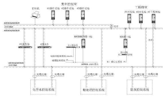
Figure 2 Huaneng Luoyang Thermal Power Auxiliary Control Network Structure Diagram
The entire auxiliary control DCS system shares more than 459 bus devices, with a total of 21 pairs of redundantPDP as the main station for fieldbus communication. Among them, the water treatment system has 13 pairs, the ash removal system has 3 pairs, and the precision treatment system has 5 pairs. According to the installation areas of bus devices, a total of 15 on-site fieldbus cabinets were configured, among which the water treatment system has 8 cabinets, the ash removal system has 4 cabinets, and the precision treatment system has 3 cabinets. These on-site bus cabinets are distributed in various areas of the auxiliary control system, connected to the main station of the PDP bus communication through redundant optical fibers.
When segmenting, the fiber distance from the on-site bus cabinet to the PDP bus communication main station can be ignored. In allocating the DP segment, the entire segment length from the bus cabinet to the last device and back to the bus cabinet must not exceed 400m. For the PA segment, since junction boxes can be placed next to the devices, the segment distance only considers the distance from the bus cabinet to the farthest junction box of that segment, and the maximum segment distance is 1000m, thus the PA segment distance generally will not exceed this limit.
4. Precautions in Debugging Fieldbus Devices
(1) The connection between field devices and the Profibus-DP fieldbus adopts DP9 connectors, and the network segment devices are connected in a daisy chain. Each DP9 connector is equipped with 1 terminal resistor, except for the last 1 device in the daisy chain, whose terminal resistor is set to ON while the others are set to OFF.[4].
(2) In the bus network, the ABB RLM01 is the gateway device for converting optical fibers to DP bus. When debugging communication, it is important to ensure that the baud rate setting on the RLM01 matches the system’s baud rate setting.
(3) The addresses of the bus devices and the addresses configured in the DCS system must be consistent.
(4) The cable layering, grounding, and shielding connections must be carried out according to the installation specification requirements. For Profibus DP bus devices, multi-point grounding should be performed according to DP specifications. After the connections are completed, signal validation should be conducted to ensure reliable signal transmission[5]. Dedicated tools such as Profitrace analyzer can be used to diagnose Profibus fieldbus links to ensure that there are no hardware link issues, saving debugging time.
(5) The GSD file is the protocol document for data communication between bus devices and the DCS, which specifies the types and quantities of communication data between bus devices and the DCS. It is essential to use the same version of the GSD file as the field devices to prevent configuration errors or anomalies[4]. During on-site debugging, if data communication cannot be established, after eliminating physical link and system setting issues, it is necessary to confirm with the device manufacturer whether the GSD file is consistent with the model of the bus device. Generally, the bus device needs to be sent to the ABB manufacturer for testing before on-site installation to verify whether the communication with the DCS system is normal and to issue a test report, thus reducing the workload during on-site debugging and improving debugging efficiency.
(6) For some bus devices, after successful communication, it is also necessary to disassemble and calculate the read data according to the variable address table provided by the manufacturer.
5. Summary and Outlook
For the auxiliary control system of power plants, the on-site devices and measurement points are widely distributed; adopting fieldbus devices and fieldbus control networks can significantly reduce the amount of hard wiring installation and connection work. However, at the same time, adopting bus communication, different devices in the same segment are connected in a single communication cable, and once the communication cable is disconnected or the communication master station fails, it will affect all devices in that segment. Therefore, a redundant communication cable strategy is usually adopted to enhance the reliability of the entire control network. The fieldbus network of the Symphony Plus system truly achieves dual network redundancy, even for single DP bus devices, redundancy through the communication master station enhances the reliability of the bus network.
The auxiliary control system based on the Symphony Plus fieldbus network has strong information processing and management capabilities. However, in practical applications, limited by on-site bus devices and existing control strategies, it has not achieved management automation and remote fault diagnosis functions, weakening the intelligent functions of the bus control system.
Currently, bus control systems have been widely applied in power plants, which is conducive to achieving digitalization in power plants and laying a solid foundation for future mature intelligent management. With the improvement of control strategies, the intelligent upgrades of on-site devices, and the enhancement of bus control systems, the reliability and safety of fieldbus systems will gradually increase, thereby better utilizing the intelligent functions of fieldbus systems, reducing operational maintenance costs, and improving the management quality of power plants.
References
[1] Jin Qianjun. Application research of fieldbus technology in auxiliary systems of power plants. Electric Power Construction, 2006, 27(2): 11-12.
[2] Liao Yongxin. Problems and countermeasures of fieldbus control in thermal power plants. Thermal Power Generation, 2014, 40(1): 13-15
[3] Yang Xinmin. Application of fieldbus technology in thermal power plants. Thermal Power Generation, 2014, 43(9): 76-78
[4] Tian Shuang. Water network control system based on FF and Profibus fieldbus in Huadian Laizhou Power Plant. Thermal Power Generation, 2013, 42(1): 91-93
[5] Guo Xiaojie. Research on the application of fieldbus control systems in the second phase of Shazhou Power Plant. Power Generation Technology, 2014, (5): 59-62
About This Competition
With the proposal of the “Internet +” concept and the release of “Made in China 2025”, concepts such as intelligent manufacturing and industrial internet have become current hot topics. The recently announced “13th Five-Year Plan” emphasizes the implementation of an innovation-driven development strategy and strengthens the leading role of technological innovation. The “Go Game Human-Machine Battle” has also sparked a wave of discussion about artificial intelligence and future technology. The China Automation Society, as a national academic social organization in this field, held the 8th National Automation System Engineer Paper Competition. The competition provides an important platform for technical exchange and experience sharing in the field of automation in China, promotes the close integration of the automation industry and academic research, and effectively promotes the development of the industry.
Follow us

Long press to recognize the QR code for more wonderful content
Click “Read Original” below for more, reprint please indicate the source
↓↓↓