0x00
This article is dedicated to daily learning and note sharing to help everyone learn assembly language. Why learn assembly language? Because in red-blue confrontations, our tools are often detected and killed by some AV/EDR. Therefore, we need to counter AV, which is the evasion technique. To learn evasion techniques, we must start from the basics. In the future, I may also share some notes on C++, PE file structures, etc. Additionally, I may introduce knowledge related to reverse engineering.
0x01
1. Principles of CPU Interaction with Registers
Overview of Registers
1. The 8086 CPU has 14 registers, named AX, BX, CX, DX, SI, DI, SP, BP, IP, CS, SS, DS, ES, and PSW. Among them, AX, BX, CX, and DX are used to store general data and are called general-purpose registers.
2. All registers in the 8086 CPU are 16 bits, capable of storing two bytes, i.e., 1 word, with a maximum data value of 2^16 – 1.
3. Logical structure of general-purpose registers:
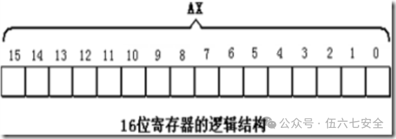
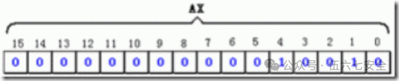
4. A 16-bit register can store a 16-bit data
Data: 2000
Storage in register AX:
5. In the previous generation of CPUs before the 8086, all registers were 8 bits; to ensure compatibility, these four general-purpose registers can be divided into two independent 8-bit registers.
AX can be divided into AH and AL, where AH is the high byte and AL is the low byte.
Both AH and AL registers can be used independently as 8-bit registers.
Storage of Words in Registers
For compatibility reasons, the 8086 CPU can handle the following two sizes of data at once:
- Byte, 1 byte = 8 bits, can be stored in an 8-bit register.
- Word, a word consists of two bytes, namely the high byte and the low byte.
A word can be stored in a 16-bit register, with the high byte and low byte naturally residing in the high 8 bits and low 8 bits of the register. 1 word = 2 bytes = 16 bits.
Some Assembly Instructions
Assembly Instruction    Operation Controlled by CPU    High-level Language Syntax Description
mov ax,8            Load 18 into AX                AX=18
mov ah,20           Load 20 into AH                AH=20
add ax,8            Add 8 to the value in register AX  AX=AX+8
mov ax,bx          Load data from register BX into register AX  AX=BX
add ax,bx          Add contents of AX and BX, result stored in AX  AX=AX+BX
Note:
1. Assembly language is case insensitive!
2. When transferring data or performing operations, ensure that the bit sizes of the two operands are the same!
Physical Address
1. When the CPU accesses memory units, it must provide the address of the memory unit. All memory units form a one-dimensional linear space.
2. In summary, a 16-bit structure describes the following characteristics of a CPU:
1) The arithmetic unit can process a maximum of 16 bits of data at a time;
2) The maximum width of registers is 16 bits;
3) The pathway between registers and the arithmetic unit is 16 bits.
3. The 8086 has a 20-bit address bus, capable of transmitting 20-bit addresses, with an addressing capacity of 1M; however, the internal structure of the 8086 is 16 bits, so it can only transmit 16-bit addresses, resulting in an effective addressing capacity of only 64K.
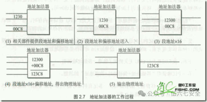
4. The method for the address adder to generate a physical address: Physical Address = Segment Address * 16 + Offset Address!!!
Method for the 8086 CPU to Provide Physical Addresses
1. Relevant components in the CPU provide two 16-bit addresses, one called the segment address and the other the offset address;
2. The segment address and offset address are sent through an internal bus to a component called the address adder;
3. The address adder combines the two 16-bit addresses into a single 20-bit address.
Concept of Segments
1. Misconception: Memory is divided into segments, each with a segment address.❌❌❌❌
2. In fact: Memory is not segmented; the segmentation comes from the CPU. The 8086 CPU provides the physical address of memory units using the formula “(Segment Address * 16) + Offset Address = Physical Address”, which makes it appear as if memory is managed in a segmented manner.
3. In practice, several contiguous memory unit addresses can be viewed as a segment, using Segment Address * 16 as the actual address (base address) of the segment, and using the Offset Address to locate memory units within the segment.
4. Data in memory unit 21F60H can be described in two ways for the 8086 PC:
1) Data exists in memory unit 2000:1F60;
2) Data exists in memory unit 1F60 of segment 2000.
Two points to note:
1. Segment Address * 16 is always a multiple of 16, so the starting address of a segment must also be a multiple of 16;
2. The Offset Address is 16 bits. The addressing capacity of a 16-bit address is 64KB, so the maximum length of a segment is 64KB.
Memory Unit Address
1. When the CPU accesses memory units, it must provide the physical address of the memory unit;
2. The 8086 CPU internally forms the final physical address by adding the segment address and offset address.
Consider two questions:
1. Observing the addresses below, what do readers notice?
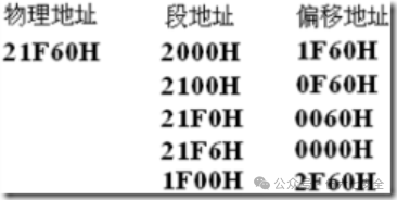
Conclusion: The CPU can form the same physical address using different segment and offset addresses.
2. If a segment address is given, how many memory units can be located by varying only the offset address?
Conclusion: The Offset Address is 16 bits, with a range of 0~FFFFH, so using only the Offset Address for addressing can locate a maximum of 64K memory units.
For example: Given a segment address of 1000H, using the offset address for addressing, the CPU’s addressing range is 1000H~1FFFFH.
Segment Registers
1. Segment registers provide segment addresses; the 8086 CPU has 4 segment registers: CS (Code Segment Register), DS (Data Segment Register), SS (Stack Segment Register), and ES (Extra Segment Register).
2. When the 8086 CPU needs to access memory, these 4 segment registers provide the segment addresses of the memory units.
3. CS and IP are the most critical registers in the 8086 CPU, indicating the address of the instruction the CPU is currently reading.
CS is the Code Segment Register, and IP is the Instruction Pointer Register (usually stores the offset address).
4. The mov instruction cannot be used to set the values of CS and IP; the 8086 CPU does not provide such functionality.
CS and IP
CS and IP are the most critical registers, indicating the address of the instruction the CPU is currently reading. CS is the code register, and IP is the pointer register.
The working process of the 8086 CPU is briefly described as follows:
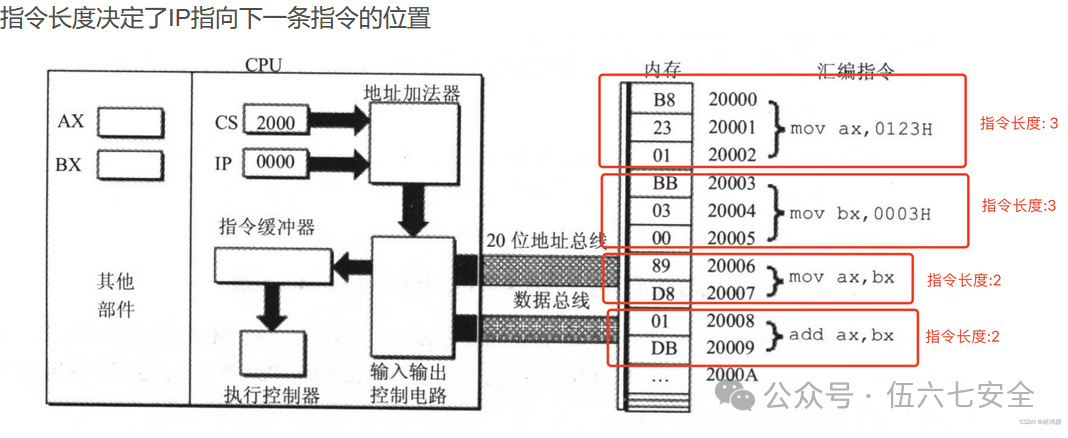
- Read the instruction from the memory unit pointed to by CS:IP, and the read instruction enters the instruction buffer.
- IP = IP + length of the read instruction, thus pointing to the next instruction.
- Execute the instruction, return to step 1, and repeat this process.
After powering on or resetting the 8086 CPU, CS = FFFFH, IP = 0000H, and the CPU starts executing from FFFF0H.
Now let’s introduce the complete workflow:
CS points to the segment address
IP points to the offset address
The CPU treats the contents pointed to by CS:IP as instructions to execute.
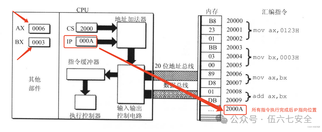
The process of the CPU reading instructions is as follows:
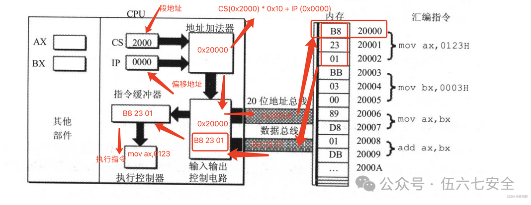
The CPU obtains the segment address and offset address from CS:IP, calculates the memory unit address through the address adder, then reads the instruction from memory through the input-output control circuit via the 20-bit address bus, and finally executes the instruction.
After executing the first instruction, changes occur, and the process of executing the second instruction begins:
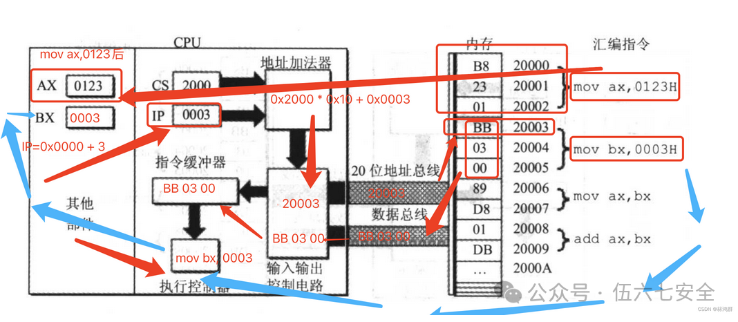
IP will change with the instruction.
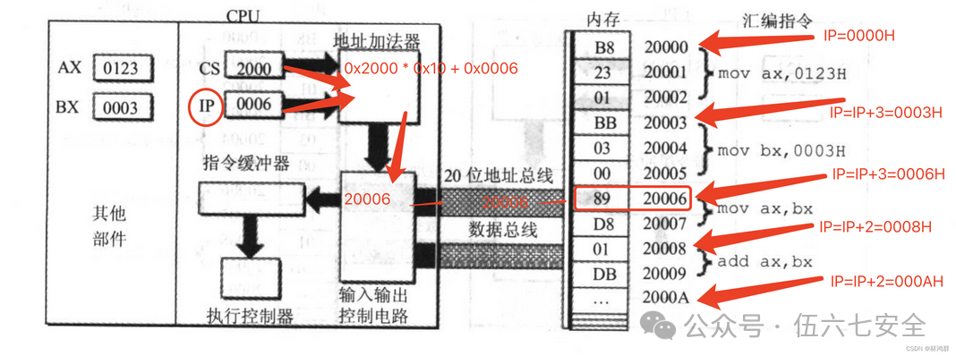
After all instructions are executed, the segment register and instruction pointer register change.
Modifying CS and IP
In the CPU, the programmer can only read and write to registers using instructions, but the mov instruction cannot be used to set the values of CS and IP; transfer instructions (jmp) must be used.
If you want to modify the contents of CS and IP simultaneously, you can use a command like jmp segment address: offset address, for example:
jmp 2AE3:3        After execution CS=2AE3H, IP=0003H   Read instruction from 2AE33H
jmp 3:0B16        After execution CS=0003H, IP=0B16H   Read instruction from 00B46H
If you only want to modify the content of IP, you can use jmp to a valid register to represent the modification of IP using the content in the register.
jmp ax    Before execution ax=1000h    cs=2000h   ip=0003h
          After execution ax=1000h    cs=2000h   ip=1000h
Brief Description of the Interaction Process of the 8086 PC
1. After powering on or resetting the 8086 CPU (i.e., when the CPU first starts interacting), CS and IP are set to CS=FFFFH, IP=0000H.
2. When the 8086 PC starts up, the CPU reads and executes instructions from memory unit FFFF0H.
3. The instruction in unit FFFF0H is the first instruction executed after the 8086 PC is powered on.
Experiment: Use the Debug command to check the production date of your motherboard’s ROM
Tip: The production date of the ROM is in several units of memory from FFFF0H to FFFFFH.
Using Debug
Debug is a debugging tool provided by DOS and Windows in real mode (8086 mode), which allows you to view the contents of various CPU registers, memory status, machine code, and trace program execution.
Debug Functions Used
- R command to view and change the contents of CPU registers
- D command to view the contents of memory
- E command to rewrite the contents of memory
- U command to translate machine instructions in memory into assembly instructions
- T command to execute a machine instruction
- A command to write a machine instruction in memory in assembly instruction format
R Command
First, after entering debug, type r to view all register contents.
Modify the contents of the register, for example, change the value of ax to 200.
r  ax
200
D Command
The D command views memory contents,d uses segment address: offset address to view
d 1000:0    View contents at 1000:0
d 1000:0 9  View contents from 1000:0 to 1000:9
Using the D command will output three parts:
The middle part shows the contents of 128 memory units starting from the specified address, output in hexadecimal format, with each line starting from an address that is a multiple of 16, outputting a maximum of 16 units of content per line, with a “-” in the middle for easier viewing.
The left side shows the starting position of each line.
The right side shows the ASCII characters corresponding to the data in each memory unit; if there is no corresponding character, it is represented by a “.”.
E Command
The E command can rewrite the contents of memory, for example, to change the contents of 1000:0~1000:9 to 0~9, you can use e 1000:0 0 1 2 3 4 5 6 7 8 9 to do so.
You can also modify one address at a time using the following steps:
- Input e 1000:10, press Enter
- Debug displays the original content of unit 1000:0010
- Input data to modify the current memory unit, or do not input data and press space to not modify.
- After completing the current unit, press space to end the modification and automatically move to the next unit.
- After all modifications are complete, press Enter to finish.
You can use the E command to write characters, for example, e 1000:0 1 ‘a’ 2 ‘b’ to write the ASCII values of 1, a, 2, b.
You can also write character strings, for example, e 1000:0 1 “a+b” 2 “c++”to write the ASCII values of 1, a+b, 2, c++.
You can also write machine code, using U to view the meaning of machine code in memory, and using T command to execute the machine code in memory, for example, writing these three:
Machine Code                Corresponding Assembly Instruction
b80100                mov ax,0001
b90200                mov cx,0002
01c8                add ax,cx
You can use e 1000:0 b8 01 00 b9 02 00 01 c8 to complete this.
U Command
The U command can view the assembly instructions corresponding to machine code in memory, for example, u 1000:0 to view.
The output of the U command is divided into three parts:
- The address of each machine instruction
- The machine instruction
- The assembly instruction corresponding to the machine instruction
T Command
The T command can execute one or more instructions; simply using the T command can execute the instruction pointed to by CS:IP.
- First, use the E command to write machine code to the target memory unit.
- Use the R command to check the status of the CPU registers and modify CS:IP to point to the target address.
- The T command executes the written instruction, and debug displays the status of the registers after execution.
A Command
The A command writes machine instructions in assembly instruction format; after entering the starting address, simply press Enter to indicate the end of the operation.
a  1000:0
1000:0000  mov ax,1
1000:0003  mov bx,2
1000:0005  mov cx,3
Debug Installation
Debug installation tutorial: https://www.cnblogs.com/zhaijiahui/p/10148698.html

ASMT00ls: https://www.yuque.com/desktop/auth?url=https%3A%2F%2Fwww.yuque.com%2Fattachments%2Fyuque%2F0%2F2025%2Frar%2F46595978%2F1750241004893-8fdee8b4-4083-46df-8686-f099c4123c37.rar%3Ffrom%3Dhttps%253A%252F%252Fwww.yuque.com%252Fyizhiyiyudebuoumao%252Fysr4tp%252Figgn8qdeqy6uva82&token=encrypted%7CsN7SGO0v2US-KGseTh0jmbaSJcNPvME0PlAAwRnmkzVp4VWiKtkHcF6KwSoCcloW0VQg4zr7lhUV26fc9hQx1mxpC9GdJGTzeQYZDmATPKfFvuwk9MIZq5253NilWxZqpbC2we4c-kt6DQIwTNeZ631iDSEPerjQetlq7x0Nf9QtYyjgwX_cpD30rMRZaQnpdmeHxmoxQGeXUdkBf_MhXzvHH8UBVjtbpbxYvx-mMraHwazElOi6yS1n040dA9SFKKPIFfPIslzGICAy33L7uR2WXQL-pMhhBEP-895BGZU%3D

Or use a Windows 2003 virtual machine and directly enter debug in cmd.
ASMTools:
📎AsmTools.rar
0x02
Previous Notes:
Basic Knowledge of Assembly Language
Previous Exciting Practices:
Domain Forest Breach from the Red Team Perspective: A Cross-Domain Control Attack and Defense Confrontation Triggered by Shiro Deserialization
Practice – From Shiro Deserialization to Domain Control
“Nuclear Explosion Effect” After Domain Control Takeover: Harvesting Permissions from 1600 Hosts Based on DCSync and Golden Tickets
0x03
Fan Benefits:
1.6K Hosts Full Domain Compromise Record (Lottery at the end)
 Share
Share Collect
 Looking
 Like
Like

Scan to Follow UsBecome an Excellent Network Security Guard