Learn Assembly Language / Comprehensive Review
3, 5, 7, and 8 are programming question sources. The compulsory exam format at our Nanchang campus consists of 20 points for multiple choice, 30 points for short answers, and 50 points for programming. You can find the PDF version of this article in the group files or database.
0. Overview of Learning Review
Machine language is a collection of machine instructions.
Assembly language is a mnemonic for machine instructions, corresponding one-to-one with machine instructions.
The process of writing a program in assembly language: the programmer writes the source program in assembly language, then uses an assembler to compile it into machine code, which is ultimately executed by the computer.
Components of assembly language instructions: assembly instructions, pseudo-instructions, and other symbols.
In memory, instructions and data are indistinguishable; both are binary information.
Memory units are sequentially numbered starting from zero.
A memory unit can store 8 bits, i.e., an 8-bit binary number.
The CPU’s read/write process for memory: (1) The CPU sends address information via the address bus; (2) The CPU sends memory read/write instructions via the control bus, selects the memory chip, and notifies it whether to read data from or write data to it; (3) The memory sends data from a specific unit to the CPU via the data bus, or the CPU sends data to the memory unit via the data bus.
The width of the address bus determines the CPU’s addressing capability.
The width of the data bus determines the amount of data transferred in one operation between the CPU and other components.
The width of the control bus determines the CPU’s control capability over other components in the system.
A typical CPU consists of an arithmetic logic unit, a controller, registers, and other components, all connected by an internal bus.
The arithmetic logic unit processes information, registers store information, the controller manages the operation of various components, and the internal bus connects these components for data transfer.
DEBUG commands
| R | View or change the contents of CPU registers |
|---|---|
| D | View contents in memory |
| E | Modify contents in memory |
| U | Translate machine instructions in memory to assembly instructions |
| T | Execute a machine instruction |
| A | Write a machine instruction in memory in assembly instruction format |
| P | Skip the loop instruction |
| G | Execute to a specified memory address |
A word unit: a memory unit that stores a word-sized data (16 bits), composed of two consecutively addressed memory units, using little-endian storage (high bits in high addresses, low bits in low addresses).
When accessing a memory unit with the mov instruction, you can specify only the offset address in the mov instruction; in this case, the segment address defaults to the DS register.
[address] represents a memory unit with an offset address of address.
When transferring word-sized data between memory and registers, high address units correspond to high 8-bit registers, and low address units correspond to low 8-bit registers.
The segment address and offset address of the stack top are stored in the SS and SP registers.
Execution steps of the PUSH instruction: ① SP=SP-2; ② Data is sent to the word unit pointed to by SS:SP.
Execution steps of the POP instruction: ① Data is read from the word unit pointed to by SS:SP; ② SP=SP+2.
At any moment, SS:SP points to the top element of the stack.
The 8086 CPU only records the stack top; the size of the stack space must be managed manually.
When using the stack to temporarily store data, the order of popping must be the reverse of the order of pushing.
The PUSH and POP instructions are essentially memory transfer instructions; note to apply them flexibly.
In assembly source programs, data cannot start with a letter; A000h must be written as 0A000h.
[idata] is interpreted by DEBUG as a memory unit and by the compiler as idata, so in assembly source programs, if you access a memory unit with an instruction, you must use […] to represent the memory unit in the instruction. If you directly give the offset address of a memory unit in [ ] with a constant idata, you must explicitly provide the segment address in the segment register before the [ ], for example, mov al, ds:[0], where “ds:” is called the segment prefix. If you use a register like bx in [ ], the segment address defaults to ds.
dw ? defines word-sized data, db ? defines byte-sized data, dd ? defines double word-sized data, ? Dup (?) defines data in bulk.
The pseudo-instruction end marks the entry address label of the program.
The method of defining a segment is the same as defining a code segment; different segments have different names, and when referencing segment addresses, the segment name acts as a label representing the segment address.
Transfer instructions are divided into intra-segment transfers (only modify IP) and inter-segment transfers (modify both CS and IP).
Intra-segment transfers are divided into short transfers (-128~127) and near transfers (-32768~32767).
The transfer instructions of the 8086 CPU include: unconditional transfer instructions, conditional transfer instructions, loop instructions, procedures, and interrupts.
The function of the offset operator is to obtain the offset address of a label.
The significance of transferring based on displacement is to ensure that a segment of code can execute correctly when loaded at different memory locations.
1. Working Principle of the 8086 CPU
(1) Read instructions from the memory unit pointed to by CS:IP, and the read instruction enters the instruction buffer.
(2) IP=IP+length of the read instruction, thus pointing to the next instruction.
(3) Execute the instruction. Go back to step 1 and repeat this process.
After powering on or resetting the 8086 CPU, CS and IP are set to CS=FFFFH, IP=0000H.
2. Method of Providing Physical Addresses by the 8086 CPU and Locating Memory Addresses
The 8086 CPU uses a method of combining two 16-bit addresses internally to form a 20-bit physical address.
The address adder combines the physical address using the formula Physical Address = Segment Address × 16 + Offset Address.
The essence is that when the CPU accesses memory, it adds a base address (segment address × 16) to an offset address relative to the base address to provide the physical address of the memory unit.
3. [BX] and LOOP Instructions
[BX]: represents a memory unit whose offset address is in bx.
LOOP instruction: loop label, when executed by the CPU, performs two operations: ① (cx)=(cx)-1; ② Checks the value in cx; if not zero, it jumps to the label to execute the program; if zero, it continues down.
Programming, sequentially transferring data 0~63 (3FH) to memory 0:200-0:23F, using only 9 instructions, including “mov ax,4c00h” and “int 21h”.
assume cs:code
code segment
        mov ax,0020h
        mov ds,ax
        mov bx,0
        mov cx,40h ; loop 64 times
    s:  mov [bx],bx
        inc bx
        loop s

        mov ax,4c00h
        int 21h
code ends
end
4. Two Basic Issues in Data Processing and Comprehensive Application of Addressing Modes
Where is the data being processed?
For machine instructions: memory, CPU internal registers, CPU internal instruction buffers.
For assembly language: immediate values (idata), registers, segment addresses, and offset addresses.
How long is the data to be processed?
The 8086 CPU can process two sizes of data: byte and word, so in machine instructions, it is necessary to specify whether the instruction is performing word operations or byte operations. Assembly language handles this in the following ways.
(1) By specifying the size of the data to be processed through the register name.
(2) In the absence of a register name, using the operator X ptr to specify the length of the memory unit, where X can be word or byte in assembly instructions.
(3) Other methods, some instructions default to accessing either sub-units or byte units, such as push.
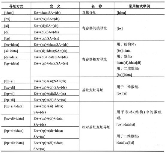
Addressing modes
Experiment 7, Application of Addressing Modes in Structured Data Access
assume cs:code,ds:data,ss:stack

data segment

db '1975','1976','1977','1978','1979','1980','1981','1982','1983'
db '1984','1985','1986','1987','1988','1989','1990','1991','1992'
db '1993','1994','1995'
; Year data

dd 16,22,382,1356,2390,8000,16000,24486,50065,97479,140417,197514
dd 34590,590827,803530,1183000,1843000,2759000,3753000,4649000,5937000
; Income data

dw 3,7,9,13,28,38,130,220,476,778,1001,1442,2258,2793,4037,5635,8226
 dw 11542,14430,15257,17800
; Employee number data

data ends

table segment
    db 21 dup ('year summ ne ?? ')
table ends

stack segment
    dw 8 dup (0)

stack ends

code segment
    start:mov ax,data
          mov ds,ax
          mov ax,stack
          mov ss,ax
          mov sp,10h
          mov ax,table
          mov es,ax
          mov bx,0 ; increment in table by 10h
          mov di,0 ; increment in data
          ; First loop for year data
          mov cx,21
    s10:  mov si,0 ; increment within element
          push cx
          mov cx,4
    s00:  mov al,ds:[di]
          mov es:[bx+0h+si],al
          inc si
          inc di
          loop s00
          add bx,10h
          pop cx
          loop s10
          ; Second loop for income data
          mov bx,0
          mov cx,21
    s11:  mov si,0 ; increment within element
          push cx
          mov cx,4
    s01:  mov al,ds:[di]
          mov es:[bx+5+si],al
          inc si
          inc di
          loop s01
          add bx,10h
          pop cx
          loop s11
          ; Third loop for employee number data
          mov bx,0
          mov cx,21
    s12:  mov si,0 ; increment within element
          push cx
          mov cx,2
     s02: mov al,ds:[di]
          mov es:[bx+10+si],al
          inc si
          inc di
          loop s02
          add bx,10h
          pop cx
          loop s12

          mov di,0
          ; Fourth loop to calculate and write average income data
          mov bx,0
          mov cx,21
    s13:  mov si,0
          mov ax,es:[bx+5]  ; low 16 bits
          mov dx,es:[bx+7]  ; high 16 bits
          div word ptr es:[bx+10]
          mov es:[bx+13],ax
          add bx,10h
          loop s13

          mov ax,4c00h
          int 21h

code ends
end start
5. CALL and RET Instructions and Subroutine Design
The ret instruction uses data from the stack to modify the content of IP, thus achieving near transfer (pop IP);
the retf instruction uses data from the stack to modify the contents of CS and IP, thus achieving far transfer (pop IP / pop CS).
The call instruction pushes the current IP or CS and IP onto the stack, then transfers.
We typically use call and ret instructions to implement the subroutine mechanism, with the subroutine framework as follows:
call label
label:
instruction
ret
Using registers to store parameters and results is the most common method.
Data that needs to be passed in bulk is placed in memory, and the starting address of the memory space is placed in a register.
At the beginning of the subroutine, all the contents of the registers used in the subroutine are saved, and before returning from the subroutine, they are restored, which can be done using the stack to save the contents of the registers.
Programming, displaying a string
Name: show_str
Function: Display a null-terminated string at a specified position with a specified color.
Parameters: (dh)=line number (range 0~24), (dl)=column number (range 0~79)
(cl)=color, ds:si points to the string’s starting address
Returns: none
Application example: Display the string in the data segment in green at row 8, column 3 on the screen.
assume cs:code
data segment
    db 'This is my assembly thing 612348',0
data ends

code segment
start:  mov dh,10 ; line number 0-24
        mov dl,15 ; column number 0-79
        mov cl,7 ; color
        mov ax,data
        mov ds,ax
        mov si,0 ; ds:si points to string address
        call show_str

        mov ax,4c00h
        int 21h

show_str:

        push ax
        push bx
        push es
        push di
        push cx
        push dx

        mov ax,0b800h
        mov es,ax ; store video memory address in es
        mov al,dh
        mov bl,160
        mul bl ; row * 160 bytes to ax

        mov bh,0
        mov bl,dl
        add ax,bx
        add ax,bx ; column data stored in bx and added twice to ax
        mov di,ax ; di stores the calculated video memory offset address

        mov dx,0
        mov dl,cl ; dl stores color value, freeing cl for loop check

    s:  mov ch,0
        mov cl,ds:[si]
        jcxz ok ; use cx and jcxz to check loop
        mov byte ptr es:[di],cl
        mov byte ptr es:[di+1],dl
        inc si
        add di,2
        jmp short s
    ok:
        pop dx
        pop cx
        pop di
        pop es
        pop bx
        pop ax

        ret

code ends
end start
Programming, solving division overflow issues
Name: divdw
Function: Perform division operations that will not cause overflow, with the dividend being dword type, divisor being word type, and result being dword type.
Parameters: (ax)=low 16 bits of dword type data
(dx)=high 16 bits of dword type data
(cx)=divisor
Returns: (dx)=high 16 bits of the result, (ax)=low 16 bits of the result
(cx)=remainder
Application example: Calculate 1000000/10 (F4240H/0AH)
Tip
Provide a formula:
X: Dividend, range: [0, FFFFFFFF]
N: Divisor, range: [0, FFFF]
H: High 16 bits of X, range: [0, FFFF]
L: Low 16 bits of X, range: [0, FFFF]
int(): descriptive operator, takes the quotient, e.g., int(38/10) =3
rem(): descriptive operator, takes the remainder, e.g., rem(38/10)= 8
Formula: X/N = int(H/N) * 65536 + [rem(H/N) * 65536 + L] / N
This formula transforms the potentially overflowing division operation: X/N, into multiple non-overflowing division operations. All division operations on the right side of the equation can be performed using the div instruction, which will not cause division overflow.
assume cs:code
code segment
start:  mov ax,4240h
        mov dx,000fh
        mov cx,0ah
        call divdw

        mov ax,4c00h
        int 21h
divdw:
        push bx
        push si
        push di

        mov si,dx ; store high 16 bits
        mov di,ax ; store low 16 bits
        mov bx,cx ; store divisor

        mov ax,dx
        mov dx,0
        div cx ; rem h/n
        ; remainder h/n is in dx, needs to be used as high part of dividend
        mov ax,di ; directly put low part into ax
        div cx ; now dx & ax is the lower part, perform division on n, result in ax quotient dx remainder
        push ax
        push dx

        mov ax,si
        mov dx,0
        div cx
        ; quotient is in ax
        mov dx,ax
        pop cx
        pop ax

        pop di
        pop si
        pop bx
        ret
code ends
end start
Value display
Name: dtoc
Function: Convert word-sized number to a string representing a decimal number, with the string ending with 0.
Parameters: (ax)=word-sized data, ds:si points to the string’s starting address
Returns: none
Application example: Programming to display the data 12666 in decimal form at row 8, column 3 on the screen in green. In the display, we call the first subroutine of this experiment, show_str.
assume cs:code

data segment
    db 10 dup (0)
data ends

code segment
start:  mov ax,12666
        mov bx,data
        mov ds,bx
        mov si,0
        call dtoc

        mov dh,8
        mov dl,3
        mov cl,2
        call show_str

        mov ax,4c00h
        int 21h

dtoc:   push ax
        push dx
        push cx
        push si

d_c:    mov cx,ax ; calculate remainder one by one
        jcxz d_ok ; each time will put ax's quotient into cx to check if 0
        mov dx,0
        mov cx,10
        call divdw
        add cl,30h ; get ascii code
        push cx ; push to stack to avoid reversing
        inc si ; record the number of pushes

        jmp short d_c

    d_ok:   ; first give the number of pushes stored in si to cx as loop count
        mov cx,si
        mov si,0
    d_p:    ; pop to dx and then give to ds:[si] corresponding data block
        pop dx
        mov ds:[si],dl
        inc si
        loop d_p ; loop for count, cx records the count

        pop si
        pop cx
        pop dx
        pop ax

        ret

divdw:

show_str:
        ; parameters dh line number dl column number cl color ds:si string address
code ends
end start
6. Functions of Each Flag Bit in the Flag Register
The flag register can store certain execution results of related instructions, providing a basis for the CPU to execute related instructions and controlling the CPU’s operational mode.
The 8086 CPU’s flag register has 16 bits, and the information stored is commonly referred to as the Program Status Word (PSW).
| 15 | 14 | 13 | 12 | 11 | 10 | 9 | 8 | 7 | 6 | 5 | 4 | 3 | 2 | 1 | 0 |
|---|---|---|---|---|---|---|---|---|---|---|---|---|---|---|---|
| OF | DF | IF | TF | SF | ZF | AF | PF | CF |
6: ZF: Zero Flag, records whether the result of the executed instruction is 0; if the result is 0, then ZF=1.
2: PF: Parity Flag, records whether the number of 1 bits in the result of the executed instruction is even.
7: SF: Sign Flag, records whether the result of the executed instruction is negative.
0: CF: Carry Flag, records the carry value of the highest significant bit in unsigned arithmetic operations, or the borrow value from higher bits.
11: OF: Overflow Flag, records whether the result of signed arithmetic operations has overflowed.
10: DF: Direction Flag, controls the increment or decrement of si and di after each operation in string processing instructions; DF=0 increments.
8: TF: Related to interrupt handling, set to 0 to avoid re-triggering interrupts while executing the interrupt handling program.
9: IF: Related to interrupt handling, set to 0 to not respond to maskable interrupts.
After executing cmp ah,bh
If SF=1, OF=0, it indicates no overflow, logical result = actual result, actual result is negative, (ah) < (bh).
If SF=1, OF=1, it indicates overflow, logical result ≠ actual result, actual result is negative, (ah) > (bh).
If SF=0, OF=1, it indicates overflow, logical result ≠ actual result, actual result is positive, (ah) < (bh).
If SF=0, OF=0, it indicates no overflow, logical result = actual result, actual result is non-negative, (ah) ≥ (bh).
7. Causes of Interrupts, Process, and Writing Interrupt Handlers
Interrupt: A capability of the CPU, indicating that it can detect special information sent from outside the CPU or generated internally after completing the currently executing instruction, and can immediately process the received information. The CPU does not continue executing the (just completed) instruction but instead processes this special information called interrupt information.
Interrupt information from within the CPU:
Division error (overflow), single-step execution, execution of into instruction, instruction int instruction.
The 8086 CPU uses a data called interrupt type code to identify the source of interrupt information.
The interrupt type code is a byte-sized data that can represent 256 types of interrupt information sources.
The source of interrupt information is called the interrupt source.
After the CPU receives interrupt information, it needs to process it. The program we write to handle interrupt information is called the interrupt handler.
The CPU uses an 8-bit interrupt type code to find the entry address of the corresponding interrupt handler through the interrupt vector table.
The interrupt vector table is a list of interrupt vectors.
An interrupt vector is the entry address of the interrupt handler.
The interrupt vector table is stored in memory; for the 8086 CPU, the interrupt vector table is specified to be stored at memory address 0. The first 1024 units from 0000:0000 to 0000:03FF store the interrupt vector table; if stored elsewhere, the 8086 CPU will not be able to read it.
In the interrupt vector table, each entry occupies two words, with the high address word storing the segment address and the low address word storing the offset address.
The memory unit address storing the offset address of the interrupt handler corresponding to interrupt source N is N×4.
The memory unit address storing the segment address of the interrupt handler corresponding to interrupt source N is N×4+2.
Interrupt process
(1) Obtain the interrupt type code N
(2) pushf
(3) TF=0 (to avoid re-triggering interrupts while executing the interrupt handler), IF=0 (do not respond to maskable interrupts)
(4) push CS
(5) push IP
(6) (IP)=(N*4), (CS)=(N*4+2)
Special case: For example, after executing an instruction to transfer data to the ss register, even if an interrupt occurs, it will not respond.
Steps to write an interrupt handler
(1) Save the registers used
(2) Process the interrupt
(3) Restore the registers used
(4) Return using the iret instruction
Generally, the space corresponding to the interrupt vector table from 0000:0200 to 0000:02FF is empty, and the operating system and other applications do not occupy it. We can send the interrupt handler to this memory space as long as we ensure that the interrupt handler does not exceed 256 bytes.
Install the interrupt handler and set the interrupt vector, taking interrupt 0 as an example, Experiment 12.
assume cs:codesg
codesg segment
    start:  ; d0 install program
            ; es:di points to target address
            mov ax,0
            mov es,ax
            mov di,200h
            ; ds:si points to source address
            mov ax,cs
            mov ds,ax
            mov si,offset d0

            mov cx,offset d0end-offset d0
            cld
            rep movsb
            ; set interrupt vector table
            mov ax,0
            mov es,ax
            mov word ptr es:[0*4],200h
            mov word ptr es:[0*4+2],0

            mov ax,4c00h
            int 21h

    d0:     ; display string
            jmp short d0start
            db 'divide error!'

    d0start:mov ax,cs
            mov ds,ax
            mov si,202h

            mov ax,0b800h
            mov es,ax
            mov di,12*160+36*2

            mov cx,13
        s:  mov al,[si]
            mov es:[di],al
            inc si
            add di,2
            loop s

            mov ax,4c00h
            int 21h
    d0end:  nop
codesg ends
end start
Interrupts triggered by the int instruction
int n, where n is the interrupt type code, functions to trigger the interrupt process.
Using this instruction, you can call any interrupt handler in the program.
Write and install the int 7ch interrupt routine, which displays a null-terminated string, with the interrupt routine installed at 0:200.
Parameters: (dh)=line number, (dl)=column number, (cl)=color, ds:si points to the string’s starting address.
assume cs:code
code segment
    start:  ; install program
            ; target area es:di
            mov ax,0
            mov es,ax
            mov di,200h

            ; source area ds:si
            mov ax,cs
            mov ds,ax
            mov si,offset showstr

            mov cx,offset showend-offset showstr
            cld
            rep movsb

            mov ax,0
            mov es,ax
            mov word ptr es:[7ch*4],200h
            mov word ptr es:[7ch*4+2],0

            mov ax,4c00h
            int 21h

    showstr:push ax
            push cx
            push si
            push di
            push bx
            ; provide segment address
            mov ax,0b800h
            mov es,ax
            ; start calculating offset address
            mov bx,0 ; use bx to store the calculated result, al for intermediate storage
            mov al,dh
            mov bh,160
            mul bh ; row * 160 stored in ax
            mov dh,0
            add dl,dl ; column number multiplied by 2
            add ax,dx ; ax stores the offset address
            ; store in di, es:di is done
            mov di,ax
            ; free ax, continue using
            mov ax,0
            mov al,cl ; color data to bl, cx to be used for comparison
            ; si points to the string to be displayed, ch is set to 0, if all 0, exit loop
    change: mov cl,[si]
            mov ch,0
            jcxz ok
            ; normally execute transfer content to video memory area
            mov byte ptr es:[di],cl
            mov byte ptr es:[di+1],al
            inc si
            add di,2
            loop change
        ok:
            pop bx
            pop di
            pop si
            pop cx
            pop ax
            iret
    showend:nop
code ends
end start
Write and install the int 7ch interrupt routine, which completes the functionality of the loop instruction.
Parameters: (cx)=loop count, (bx)=offset.
assume cs:code
code segment
    start:  ; install program
            ; target area es:di
            mov ax,0
            mov es,ax
            mov di,200h

            ; source area ds:si
            mov ax,cs
            mov ds,ax
            mov si,offset lp

            mov cx,offset lpend-offset lp
            cld
            rep movsb

            mov ax,0
            mov es,ax
            mov word ptr es:[7ch*4],200h
            mov word ptr es:[7ch*4+2],0

            mov ax,4c00h
            int 21h

    lp:
            push bp
            mov bp,sp
            dec cx
            jcxz lpret
            add [bp+2],bx

    lpret:  pop bp
            iret
    lpend:  nop
code ends
end start
The following program displays four lines of English poetry on the 2nd, 4th, 6th, and 8th rows of the screen.
assume cs:code
code segment
 s1:    db 'Good, better, best,','$'
s2:    db 'Never let it rest,','$'
s3:    db 'Till good is better','$'
s4:    db 'And better, best.','$'
s:     dw offset s1,offset s2,offset s3,offset s4
row:   db 2,4,6,8

 start: mov ax,cs
        mov ds,ax
        mov bx,offset s
        mov si,offset row
        mov cx,4
    ok: mov bh,0  ; set cursor
        mov dh,[si]
        mov dl,0
        mov ah,2
        int 10h

        mov dx,[bx] ; set content
        mov ah,9
        int 21h
        inc si
        add bx,2

        loop ok

        mov ax,4c00h
        int 21h
code ends
end start
8. Interface Chips and Port Access
In PC systems, the CPU can locate up to 64KB of different ports, with port addresses ranging from 0 to 65535.
Port read/write instructions: in and out.
Only ax or al can be used to store data read from the port or data to be sent to the port.
The time information stored in CMOS RAM, with each piece of information being 1 byte long, is stored in BCD code:
| Year | Month | Day | Hour | Minute | Second |
|---|---|---|---|---|---|
| 9 | 8 | 7 | 4 | 2 | 0 |
Programming to display the current date and time in the format of year, month, day, hour, minute, second.
assume cs:code
data segment
    db 9,16,8,16,7,20,4,17,2,17,0 ; year/month/day hour:minute:second
data ends
code segment

    start:  mov cx,0FFFFh
            call start0
            loop start
            mov ax,4c00h
            int 21h

    start0:
            push cx
            mov ax,data
            mov ds,ax
            mov si,0

            mov cx,11
            mov di,7A8h

    ok:     mov ah,16
            cmp [si],ah
            je to1
            mov ah,20
            cmp [si],ah
            je to2
            mov ah,17
            cmp [si],ah
            je to3
            mov dl,[si]
            call read
            call showstr

            inc si
            add di,4
            loop ok

            pop cx
            ret
    to1:
            mov al,2Fh
            call show
            inc si
            add di,2
            loop ok

    to2:
            mov al,20h
            call show
            inc si
            add di,2
            loop ok

    to3:
            mov al,3Ah
            call show
            inc si
            add di,2
            loop ok
    read:
            push dx
            push cx
            ; read port data, parameter dl address
            mov al,dl
            out 70h,al
            in al,71h

            mov ah,al
            mov cl,4
            shr ah,cl
            and al,00001111b

            add ah,30h
            add al,30h

            pop cx
            pop dx
            ret
    showstr:
            push bx
            mov bx,0b800h
            mov es,bx
            mov byte ptr es:[di],ah
            mov byte ptr es:[di+2],al
            pop bx
            ret
    show:
            push bx
            mov bx,0b800h
            mov es,bx
            mov byte ptr es:[di],al
            pop bx
            ret
code ends
end start
The CPU communicates with external devices through ports.
External interrupt sources are divided into: maskable interrupts and non-maskable interrupts.
Maskable interrupts: external interrupts that the CPU can choose not to respond to, depending on the setting of the IF bit.
Non-maskable interrupts: external interrupts that the CPU must respond to, with a fixed interrupt type code of 2.
Almost all external interrupts triggered by peripherals are maskable interrupts.
When a key is pressed on the keyboard, a scan code is generated and written into the register of the interface chip at port address 60h.
When a key is released, a scan code is also generated and written into the register.
The code generated when a key is pressed is called a make code, and the code generated when a key is released is called a break code, with break code = make code + 80h.
When keyboard input reaches port 60h, the related chip sends a maskable interrupt with an interrupt type code of 9.
If the CPU detects interrupt information and IF=1, it responds to the interrupt, triggering the interrupt process and executing the int9 interrupt routine.
The int9 interrupt routine reads the scan code; if it is a character key’s scan code, it places that scan code and the corresponding character code into the BIOS keyboard buffer in memory; if it is a control key or toggle key’s scan code, it converts it into a status byte (a byte that records the key status using binary bits) and writes it into the memory unit storing the status byte, then controls the keyboard system accordingly.
The keyboard buffer can store 15 keyboard inputs, with each keyboard input stored in a word unit, high byte for scan code, low byte for character.
0040:17 unit stores the keyboard status byte.
Experiment 15, programming to install a new int 9 interrupt routine, function: In DOS, when the “A” key is pressed, unless released, it displays “A” across the screen; other keys are processed normally.
assume cs:code
stack segment
    db 128 dup(0)
stack ends

code segment
start:  mov ax,stack
        mov ss,ax
        mov sp,128

        push cs
        pop ds

        mov ax,0
        mov es,ax

        mov si,offset int9 ; ds:si source address cs:int9
        mov di,204h ; es:di target address 0:204
        mov cx,offset int9end-offset int9
        cld
        rep movsb

        push es:[9*4]
        pop es:[200h] ; 200 202 store original int9 cs and ip
        push es:[9*4+2]
        pop es:[202h]

        cli
        mov word ptr es:[9*4],204h ; replace int9 entry address
        mov word ptr es:[9*4+2],0
        sti

        mov ax,4c00h
        int 21h
int9:   push ax
        push bx
        push cx
        push es

        in al,60h

        pushf ; match call within iret instruction to prevent stack data disorder
        call dword ptr cs:[200h] ; internally call the original int9 address

        cmp al,9eh
        jne int9ret

        mov ax,0b800h
        mov es,ax
        mov cx,0fa0h
        mov al,41h
        mov bx,0
s:      mov byte ptr es:[bx],al
        add bx,2
        loop s

int9ret:pop es
        pop cx
        pop bx
        pop ax
        iret
int9end:nop
code ends
end start
9. Important Instructions and Concepts
jmp, conditional transfer instructions, call, ret, push, pop, int, iret, cmp, loop, segmentation, addressing modes, etc.
| Operation | Instruction | Example or Note |
|---|---|---|
| Modify the value of the object | mov object1, object2 | mov ax,8 mov ax,bx mov ax,[0] mov [0],ax |
| Addition | add object1, object2 | Similar to above |
| Subtraction | sub object1, object2 | Similar to above |
| Carry addition (ax)=(ax)+(ax)+CF | adc object1, object2 | adc ax,1 |
| Borrow subtraction (ax)=(ax)-(bx)-CF | sbb object1, object2 | sbb ax,0020H |
| Simultaneously modify CS, IP content | jmp segment address:offset address | jmp 2AE3:3 |
| Only modify IP content | jmp a valid register | jmp ax |
| Push object data onto the stack | push object | push ax push ds push [0] |
| Pop data from the stack into an object | pop object | Similar to above |
| Bitwise logical AND, can clear to zero | and object1, object2 | and al,10111111B |
| Bitwise logical OR, can set to one | or object1, object2 | or al,01000000B |
| Division | div reg/memory object | div ds:[0] |
| Multiplication | mul reg/memory object | mul bx |
| IP=IP+8-bit displacement | jmp short label | jmp instruction transfers based on displacement |
| IP=IP+16-bit displacement | jmp near ptr label | |
| Modify CS (high) and IP (low) | jmp far ptr label | |
| Modify IP | jmp word ptr memory unit address | |
| Modify CS (high) and IP (low) | jmp dword ptr memory unit address | |
| If (cx)=0, transfer to label, otherwise do nothing | jcxz label | 8-bit displacement=label address – jcxz instruction’s first byte address |
| (cx)=(cx)-1; if (cx)≠0, transfer to label, otherwise continue down | loop label | 8-bit displacement=label address – loop instruction’s first byte address |
| Equivalent to push IP; jmp near ptr label | call label | |
| Equivalent to push CS; push IP; jmp far ptr label | call far ptr label | |
| Equivalent to push IP; jmp 16-bit reg | call 16-bit reg | |
| Equivalent to push IP; jmp word ptr memory unit address | call word ptr memory unit address | |
| Equivalent to push CS; push IP; jmp dword ptr memory unit address | call dword ptr memory unit address | |
| Object1 minus object2 does not store the result; only changes the flag bits based on the calculation result | cmp object1, object2 | Determine comparison result based on SF and OF flag bits |
| If equal, transfer | je | ZF=1 |
| If not equal, transfer | jne | ZF=0 |
| If less than, transfer | jb | CF=1 |
| If not less than, transfer | jnb | CF=0 |
| If greater than, transfer | ja | CF=0 and ZF=0 |
| If not greater than, transfer | jna | CF=1 or ZF=1 |
| Transfer ds:si to es:di, incrementing or decrementing si and di based on DF | movsb | |
| Transfer ds:si to es:di, incrementing or decrementing si and di twice based on DF | movsw | |
| Repeat execution of a certain instruction based on cx value | rep | Used with movsb |
| DF=0 | cld | |
| DF=1 | std | |
| Push the value of the flag register onto the stack | pushf | |
| Send data from the stack to the flag register | popf | |
| Similar to pop IP pop CS popf | iret | |
| Call the handler for interrupt n | int n | |
| Read data from the port | in al/ax, port number | |
| Write data to the port | out port number, al/ax | |
| Logical left shift, filling low bits with 0; the last bit shifted out is written to CF | shl object, count | shl al,1 |
| Logical right shift, filling high bits with 0; the last bit shifted out is written to CF | shr | shr al,cl |
| IF=1 | sti | |
| IF=0 | cli |
Details of the Div instruction
| Dividend | Divisor | Quotient / Remainder |
|---|---|---|
| AX 16 bits | reg or memory unit 8 bits | AL / AH |
| DX high 16 bits, AX low 16 bits | reg or memory unit 16 bits | AX / DX |
Details of the Mul instruction
| Multiplicand | Multiplier | Product |
|---|---|---|
| AL 8 bits | 8-bit reg or memory byte unit | AX |
| AX 16 bits | 16-bit reg or memory unit | DX high / AX low |
Addresses with a “:” at the end of the label can only be used in the code segment, not in other segments.
Data labels: a type of label that describes the length of a unit
a db 1,2,3,4,5,6,7,8
b dw 0
a and b labels do not have a colon after them; they simultaneously describe the memory address and unit length.
If you want to use data labels in the code segment to access data, you need to use the pseudo-instruction assume to link the segment where the label is located with a segment register.
Data segment
a db 1,2,3,4,5,6,7,8
b dw 0
c dw a,b
data ends
The seg operator functions to obtain the segment address of a certain label.
Direct addressing table: allows you to directly calculate the position of the element you are looking for based on the data.
setscreen:  jmp short set
    table:  dw sub1,sub2,sub3,sub4
      set:  push bx
            cmp ah,3
            ja sret
            mov bl,ah
            mov bh,0
            add bx,bx
            call word ptr table[bx]
     sret:  pop bx
            ret
Note that using direct addressing tables in interrupt routines will lead to incorrect subroutine addresses after installation.
This article was originally published on 2022/11/28