
To learn ARM, one must learn ARM instructions. ARM instructions are the interface provided to us by the CPU, and they are the key to unlocking the Pandora’s box of the CPU.
There are many ARM instructions. To help everyone get started quickly, I have compiled some of the most helpful instructions. For the operation of the Keil software, please refer to Chapter One.
Let’s get started!
0. Instruction Classification
-
Data Processing Instructions
Data processing instructions can be divided into data transfer instructions, arithmetic logic operation instructions, and comparison instructions, etc. -
Data transfer instructions are used for bidirectional data transfer between registers and memory.
-
Arithmetic logic operation instructions complete common arithmetic and logical operations. This type of instruction not only saves the operation result in the destination register but also updates the corresponding condition flags in the CPSR.
1. MOV Instruction
1. MOV
Syntax:
MOV{condition}{S} destination_register, source_operandFunction: The MOV instruction transfers data from another register, a shifted register, or loads an immediate value into the destination register. The S option determines whether the operation of the instruction affects the condition flags in the CPSR. If S is omitted, the instruction does not update the condition flags in the CPSR.
Instruction Examples:
MOV r0, #0x1 ; Transfer immediate value 0x1 to register R0
MOV R1, R0  ; Transfer the value of register R0 to register R1
MOV PC, R14 ; Transfer the value of register R14 to PC, commonly used for returning from subroutines
MOV R1, R0, LSL #3  ; Transfer the value of register R0 left-shifted by 3 bits to R1
[Note: Case insensitive]
Consider why the following assignment fails:
MOV R0, #0xfff
To understand this issue, we need to know what an immediate value is.
2. What is an Immediate Value?
An immediate value is generated by cyclically right-shifting data between 0-255.
The judgment rules are as follows:
-
Convert the data into binary form, writing it in groups of 4 bits from low to high. If the highest group is less than 4 bits, fill in zeros in front of the highest group. -
If the number of 1s is greater than 8, it is definitely not an immediate value. If it is less than or equal to 8, proceed to the next step. -
If there are 24 or more consecutive 0s in the data, cyclically left-shift by multiples of 2 to make the high bits all 0. -
Find the highest 1 bit and remove the preceding maximum even number of 0s. -
Find the lowest 1 bit and remove the following maximum even number of 0s. -
If the remaining number of bits is less than or equal to 8 bits, then this number is an immediate value; otherwise, it is not.
The number in the example is 0xfff. Let’s look at its binary:
0000 0000 0000 0000 0000 1111 1111 1111Following the above rules, the final operation result is as follows:
1111 1111 1111We can see that the remaining number of bits is greater than 8, so this number is not an immediate value. Why is there such a restriction on immediate values? We need to start from the machine code of the MOV instruction.
3. MOV Machine Code
Let’s execute the following code:
AREA Example,CODE,READONLY    ; Declare code segment Example
ENTRY ; Program entry
Start
// Test code, add at the following position, no need to paste complete code later
mov r1,#0x80000001
OVER
END
Then click the debug button to view the corresponding machine code:

The machine code for the instruction mov r1,#0x80000001 is E3A01106
Let’s analyze this machine code.

Represented in ARM instruction mnemonic as:
<opcode> {<cond>} {S} <Rd>, <Rn>, <shift_op2>The meaning of each field is as follows:
1) {<cond>}: Condition Code Field
The condition code for executing the instruction. The braces indicate that this item can be omitted.
An important feature of ARM instructions is that they can be conditionally executed. Each ARM instruction’s condition code field contains 4 bits of condition code, with a total of 16 types. Almost all instructions are conditionally executed based on the status of the condition codes in the CPSR and the settings of the instruction’s condition code field. When the conditions for executing the instruction are met, the instruction is executed; otherwise, it is ignored. The condition codes and their mnemonic suffixes are shown in the table below.
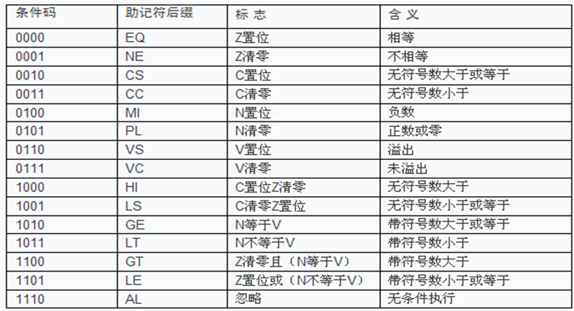
Each condition code can be represented by two characters, which can be added as a suffix to the instruction mnemonic when using the instruction.
For example: The branch instruction B can be suffixed with EQ to become BEQ, meaning “branch if equal,” which occurs when the Z flag in the CPSR is set.
2) <opcode>: Opcode Field
The mnemonic for the instruction encoding;
3) {S}: Condition Code Setting Field
This is an optional item. When the {S} field is set in the instruction, the result of the instruction execution will affect the corresponding status flags in the CPSR. For example:
ADD R0, R1, R2; R1 and R2's sum is stored in R0, does not affect the status register
ADDS R0, R1, R2; Executes addition while affecting the status register
A special instruction is CMP instruction, which does not require the S suffix but defaults to change the program status register based on the computed structure.
4) <Rd>: Destination Operand
The destination operand in ARM instructions is always a register. If it is the same as the first operand register, it must be specified and cannot be omitted.
5) <Rn>: First Operand
The first operand in ARM instructions must also be a register.
6) <shift_op2>: Second Operand
The second operand can be a register, memory storage unit, or immediate value.
If it is an immediate value:
bit:[11-8] represents the number of bits the operand is shifted left / 2,
bits:[7-0] represents the final operand
Based on the MOV instruction format, we analyze the values of each bit field:
| Bit | Meaning |
|---|---|
| 1110 | Cond ignored |
| 00 1 | |
| 1101 | opcode |
| 0 | s command does not contain S |
| 0000 | rn, no source register is 0 |
| 0001 | rd destination register R0 |
| 0001 | shifter |
| 0000 0110 | operand |
The immediate value 0x80000001 in binary is:
1000 0000 0000 0000 0000 0000 0000 0001After cyclically left-shifting 2 bits, we get the following result:
00 0000 0000 0000 0000 0000 0000 0001 10So the value of shifter is 2/2=1, and the value of the operand is 0000 0110.
2. Shift Operations
The ARM microprocessor supports data shift operations, which are not used as standalone instructions in the ARM instruction set but can only be used as a field in the instruction format, represented as an option in assembly language. Shift operations include the following 6 types: ASL and LSL are equivalent and can be interchanged freely:
1) LSL (or ASL) Logical (Arithmetic) Left Shift
Addressing format:
general_register, LSL (or ASL) operandThis completes a logical (or arithmetic) left shift operation on the contents of the general register, shifting left by the number specified in the operand, with zero filling the low bits. The operand can be a general register or an immediate value (0-31). For example:
MOV R0, R1, LSL#2 ; Transfer the contents of R1 shifted left by two bits to R0.2) LSR Logical Right Shift
Addressing format:
general_register, LSR operandThis completes a right shift operation on the contents of the general register, shifting right by the number specified in the operand, with zero filling the left end. The operand can be a general register or an immediate value (0-31). For example:
MOV R0, R1, LSR #2 ; Transfer the contents of R1 shifted right by two bits to R0, filling the left end with zeros.3) ASR Arithmetic Right Shift
Addressing format:
general_register, ASR operandThis completes a right shift operation on the contents of the general register, shifting right by the number specified in the operand, with the left end filled with the value of bit 31. The operand can be a general register or an immediate value (0-31). For example:
MOV R0, R1, ASR #2 ; Transfer the contents of R1 shifted right by two bits to R0, filling the left end with the value of bit 31.4) ROR Rotate Right
Addressing format:
general_register, ROR operandThis completes a rotate right operation on the contents of the general register, cyclically shifting right by the number specified in the operand, with the left end filled with the bits that shift out from the right end. The operand can be a general register or an immediate value (0-31). Obviously, when performing a 32-bit rotate right operation, the value in the general register does not change. For example:
MOV R0, R1, ROR #2 ; Transfer the contents of R1 rotated right by two bits to R0.5) RRX Extended Rotate Right
Addressing format:
general_register, RRX operandThis completes an extended rotate right operation on the contents of the general register, cyclically shifting right by the number specified in the operand, with the left end filled with the carry flag C. The operand can be a general register or an immediate value (0-31). For example:
MOV R0, R1, RRX #2 ; Transfer the contents of R1 in an extended rotate right by two bits to R0.Example
; Second operand register shift operation, 5 types of shift methods, 9 syntax
; Logical left shift
mov r0, #0x1
mov r1, r0, lsl #1    ; Shift amount 1-31 is definitely valid

mov r0, #0x2
mov r1, r0, lsr #1    ; Logical right shift

mov r0, #0xffffffff
mov r1, r0, asr #1    ; Arithmetic right shift, sign bit remains unchanged, next high bit fills sign bit

mov r0, #0x7fffffff
mov r1, r0, asr #1

mov r0, #0x7fffffff
mov r1, r0, ror #1 ; Rotate right

mov r0, #0xffffffff
mov r1, r0, rrx ; The only shift method that does not require specifying the shift amount
; Extended rotate right
; C flag enters the highest bit, lowest bit enters C flag

; Shift value can be the low 5 bits of another register's value, written as follows
mov r2, #1
mov r0, #0x1
mov r1, r0, lsl r2    ; Shift amount 1-31 is definitely valid

mov r0, #0xffffffff
mov r1, r0, asr r2    ; Arithmetic right shift, sign bit remains unchanged, next high bit fills sign bit

mov r0, #0x7fffffff
mov r1, r0, asr r2

mov r0, #0x7fffffff
mov r1, r0, ror r2 ; Rotate right
The above results are not screenshot. Readers can copy them to Keil for debugging to view the values in the registers and the changes in the sign bits.
3. CMP Comparison Instruction
Syntax
CMP{condition} operand1, operand2The CMP instruction is used to compare the contents of one register with the contents of another register or an immediate value, while updating the condition flags in the CPSR. This instruction performs a subtraction operation, but does not store the result, only changes the condition flags. The cmp performs a subtraction and does not save the result, merely to produce logic reflected in changing the corresponding condition bits in the CPSR.
The flags indicate the relationship between operand1 and operand2 (greater, less, equal), instruction examples:
CMP R1, R0   ; Subtract the value of register R1 from the value of register R0, and set the CPSR flags based on the result
CMP R1, #100  ; Subtract the value of register R1 from immediate value 100, and set the CPSR flags based on the result
4. TST Conditional Instruction
Syntax
TST{condition} operand1, operand2The TST instruction is used to perform a bitwise AND operation between the contents of one register and the contents of another register or an immediate value, updating the condition flags in the CPSR based on the result. Operand1 is the data to be tested, while operand2 is a bitmask, setting the corresponding flags based on the test result. When the bitwise AND result is 0, the EQ bit is set. Instruction example:
TST R1, #1 ; Used to test if the lowest bit is set in register R1 (the % indicates a binary number).Examples of Comparison Instructions and Conditional Execution
Example 1: Find the largest number among three registers
mov r0, #3
mov r1, #4
mov r2, #5
cmp r1, r0
movgt r0, r1
cmp r2, r0
movgt r0, r2
Example 2: Calculate the absolute difference of two numbers
mov r0, #9
mov r1, #15
cmp r0, r1
beq stop
subgt r0, r0, r1
sublt r1, r1, r0
For instructions with condition codes, please refer to the table “Instruction Condition Codes” in this article.
5. Data Processing Instructions
ADD
ADD{condition}{S} destination_register, operand1, operand2The ADD instruction is used to add two operands and store the result in the destination register. Operand1 should be a register, while operand2 can be a register, a shifted register, or an immediate value. Instruction examples:
ADD  R0, R1, R2           ; R0 = R1 + R2
ADD  R0, R1, #256            ; R0 = R1 + 256
ADD  R0, R2, R3, LSL#1      ; R0 = R2 + (R3 << 1)
ADC
Note that this instruction is not a shooter…
In addition to performing normal addition, it also adds the C condition flag from the CPSR. If you want to affect the corresponding bit in the CPSR, add the S suffix.
SUB
The format of the SUB instruction is:
SUB{condition}{S} destination_register, operand1, operand2The SUB instruction is used to subtract operand2 from operand1 and store the result in the destination register. Operand1 should be a register, while operand2 can be a register, a shifted register, or an immediate value. This instruction can be used for both signed and unsigned subtraction operations.
For example:
SUB  R0, R1, R2          ; R0 = R1 - R2
SUB  R0, R1, #256        ; R0 = R1 - 256
SUB  R0, R2, R3, LSL#1   ; R0 = R2 - (R3 << 1)
SBC
In addition to performing normal addition, it also subtracts the complement of the C condition flag from the CPSR, setting the corresponding flags in the CPSR based on the execution result.
The format of the AND instruction is:
AND{condition}{S} destination_register, operand1, operand2The AND instruction performs a logical AND operation on two operands and places the result in the destination register. Operand1 should be a register, while operand2 can be a register, a shifted register, or an immediate value. This instruction is often used to mask certain bits of operand1. For example:
AND R0, R0, #3 ; This instruction keeps bits 0 and 1 of R0, clearing the other bits.ORR
The format of the ORR instruction is:
ORR{condition}{S} destination_register, operand1, operand2The ORR instruction performs a logical OR operation on two operands and places the result in the destination register. Operand1 should be a register, while operand2 can be a register, a shifted register, or an immediate value. This instruction is often used to set certain bits of operand1. For example:
ORR R0, R0, #3 ; This instruction sets bits 0 and 1 of R0, leaving the other bits unchanged.BIC
This is a very practical instruction. In actual register operations, it is often necessary to clear certain bits without affecting the values of other bits, and this command can be used.
The format of the BIC instruction is:
BIC{condition}{S} destination_register, operand1, operand2The BIC instruction clears certain bits of operand1 and places the result in the destination register.
Operand1 should be a register, while operand2 can be a register, a shifted register, or an immediate value. Operand2 is a 32-bit mask. If a certain bit is set in the mask, that bit will be cleared. Unset mask bits remain unchanged.
For example:
BIC R0, R0, #0b1011 ; This instruction clears bits 0, 1, and 3 in R0, leaving the other bits unchanged.Examples of Data Processing Instructions
-
Addition Operation
mov r0, #1
mov r1, #2

add r2, r0, r1 ; r2 = r0 + r1
add r2, r0, #4
add r2, r0, r1, lsl #2 ; r2 = r0 + R1<<2 ; (R0 + R1*4)-
ADC, 64-bit Addition Implementation
; 2. adc 64-bit addition r0, r1 = r0, r1 + r2, r3
mov r0, #0
mov r1, #0xffffffff
mov r2, #0
mov r3, #0x1
adds r1, r1, r3 ; r1 = r1 + r3 must add S suffix
adc r0, r0, r2 ; r0 = r0 + r2 + c ; add with extended addition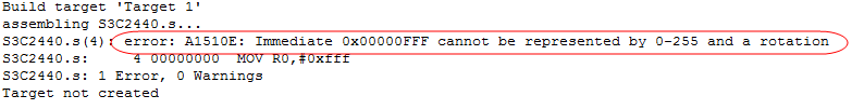 You can compare add and adds. Without adding S, it won’t affect the condition bits.
-
Subtraction
; 3. sub  rd = rn - op2
mov r0, #1
sub r0, r0, #1 ; r0 = r0 - 1-
64-bit Subtraction
; 4. sbc  64-bit subtraction r0, r1 =  r0, r1 - r2, r3
    ; cpsr c for addition, C = 1 means carry, C = 0 means no carry
 ;   For subtraction, C = 1 means no borrow, C = 0 means borrow
mov r0, #0
mov r1, #0x0
mov r2, #0
mov r3, #0x1
subs r1, r1, r3
sbc r0, r0, r2 ; sbc extended subtraction-
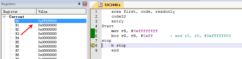
Clearing Bits
; 5. bic   Clear Bits
mov r0, #0xffffffff
bic r0, r0, #0xff       ; and r0, r0, #0xffffff00
Execution Result
6. Jump Instructions
Jump instructions are used to implement program flow jumps. In ARM programs, there are two ways to achieve program flow jumps:
-
Use dedicated jump instructions;
-
Directly write the jump address value into the program counter PC. By writing the jump address value into the program counter PC, jumps can be achieved anywhere in the 4GB address space before the jump is combined.
Using the following instruction, the future return address value can be saved, thus achieving subroutine calls in a 4GB continuous linear address space.
MOV LR, PCThe jump instructions in the ARM instruction set can complete jumps from the current instruction to a forward or backward address space of 32MB, including the following four instructions:
B        Jump instruction
BL       Branch with Link instruction
BLX      Branch with Link and state switch instruction (thumb instruction)
BX       Branch with state switch instruction (thumb instruction)
1. B Instruction
The format of the instruction is:
B{condition} target_addressThe B instruction is the simplest jump instruction. Once an ARM processor encounters a B instruction, it will immediately jump to the given target address and continue execution from there.
B label     The program unconditionally jumps to the label label for execution
CMP R1, #0
BEQ label      When the Z condition code in the CPSR register is set, the program jumps to the label Label for execution.
2. BL Instruction
The format of the BL instruction is:
BL{condition} target_addressBL is another jump instruction, but before jumping, it saves the current value of PC in register R14. Therefore, by reloading the contents of R14 into PC, it can return to the instruction after the jump instruction. This instruction is a basic but commonly used means of implementing subroutine calls.
BL label When the program unconditionally jumps to the label Label for execution, it also saves the current PC value in R14.To return from the subfunction, simply execute the following instruction:
MOV PC, LR3. BL Instruction Machine Code
Syntax:
Branch : B{<cond>} label
Branch with Link : BL{<cond>} subroutine_label
The machine code format for BL is as follows:
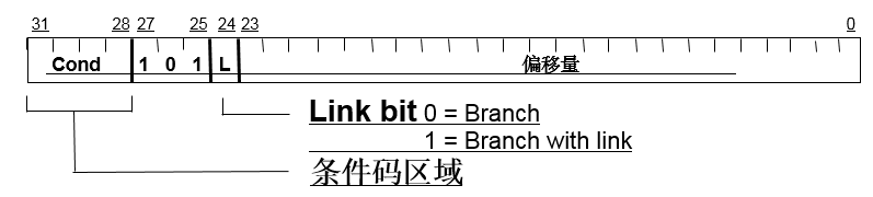
The meanings of each field:
| Field | Meaning |
|---|---|
| cond | Condition code |
| 101 | Opcode |
| L | Whether the command contains L |
| offset | Instruction jump offset |
Where offset is 24 bits, with the highest bit containing a sign bit. One unit represents an offset of one instruction, so it can address ±2^23 instructions, i.e., ±8M instructions.
And since one instruction is 4 bytes, the maximum addressing space is ±32MB of address space.
Let’s look at the following code:
AREA Example,CODE,READONLY
ENTRY ; Program entry
Start
MOV R0,#0
MOV R1,#10
BL ADD_SUM
B OVER
ADD_SUM
ADD R0,R0,R1
MOV PC,LR
OVER
END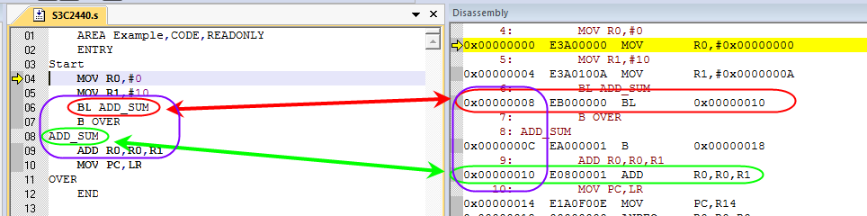
As shown in the figure above:
-
The 6th line of code BL ADD_SUM will jump to line 8, i.e., line 9 of the code. -
The machine code of the instruction in line 6 is EB000000.
According to the machine code of BL, we can see that the value of the offset is 0x000000, meaning that this instruction jumps to itself. However, according to our analysis, the instruction in line 6 should jump back two instructions, so the offset should be 2. Why is it 0?
Because of the 3-stage pipeline, the address of the PC storing the instruction is 8 bytes apart from the address of the instruction being processed. The address of the PC is the pre-fetched instruction address, not the address of the instruction being executed.
4. How to Access the Entire 32-bit Address Space?
You can manually set the LR register and then load it into the PC.
MOV lr, pc
LDR pc, =dest
During the project compilation process, the ARM linker will automatically handle long jumps (beyond the 32Mb range).
The LDR instruction will be explained in detail in the next chapter.
Example
How to return from a deeply nested subfunction call?
area first, code, readonly
code32
entry
main
  ; bl instruction, subfunction call
  mov r0,#1
  bl child_func
  mov r0,#2
stop
    b stop
child_func
 mov r1,r0
 mov r2,lr
 mov r0, #3 //<===  pc
 bl child_func_2
 mov r0,#4
 mov r0,r1
 mov lr,r2
 mov pc, lr
child_func_2 ; Leaf function
 mov r3,r0
 mov r4,lr  ; Save all registers used by the direct parent function
 mov r0, #5
 mov r0,r3
 mov lr,r4 ; Return to the direct parent function, restoring all registers used by it
 mov pc, lr
end
As shown in the example above, each time a subfunction is called, we save the return address in an ungrouped register. However, since ungrouped registers are limited, and the call depth of Linux kernel functions is often very deep, the general registers are simply not enough. To save the return address, we need to stack the data, which requires allocating space for each mode of the stack.
This article is sourced from: One Bite Linux
Hot Articles to Read:
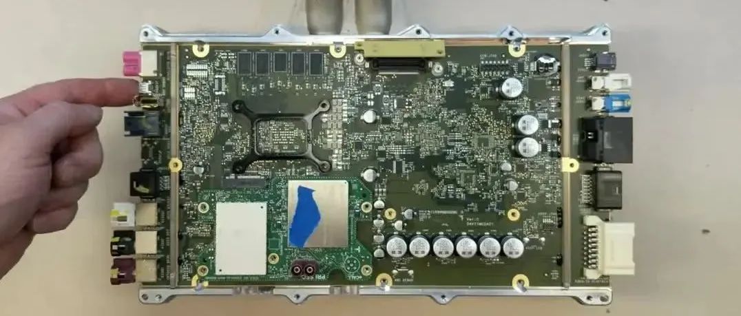
Video Analysis: Tesla’s Latest Central Computing Module (CCM)
2021-12-05
Why is the radio called “semiconductor”?
2021-12-04

Reflections of Engineers on Car Repairs: A Brief Discussion on Fault Isolation
2021-12-08

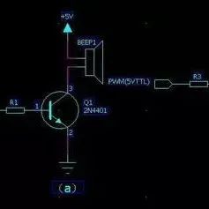
Common Misunderstandings in Using Switch Transistors
2021-12-07
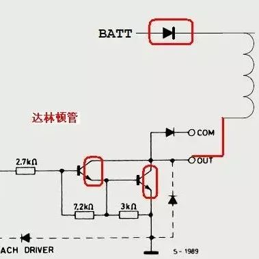
Considerations for Designing Relay Driver Circuits
2021-12-06

↓↓ Click to read the original text, apply for a development board for free