Introduction
A few years ago, I heard about a creative door lock project: the user holds a sensing device and waves it in a specific manner. Once the device recognizes the action, it unlocks the door. This action becomes a form of key.
I broke down this project into hardware and software components. The hardware part used an accelerometer to collect raw data, while the software part preprocesses the data and uses a pre-trained model to determine if the data matches the preset actions.
After a simple analysis, I felt I could first replicate the hardware part of the project and then modify the software goals according to my capabilities, simplifying it into a task I could accomplish.
After some exploration, I chose to use three LED lights to indicate the tilt status of the device. As long as the orientation of the breadboard changes, the combination of LED displays will be different.
Additionally, to achieve a total of eight combinations, I also included vertical and horizontal shaking.
Experimental Materials
Breadboard
Arduino Nano Development Board
USB-A to mini USB-B data cable
Computer
Various lengths of wires
Red LED
Green LED
Yellow LED
150Ω resistors x2
510Ω resistor
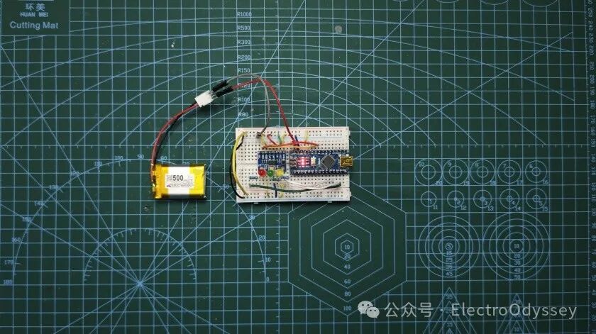
7.2V lithium battery
Hardware Connections
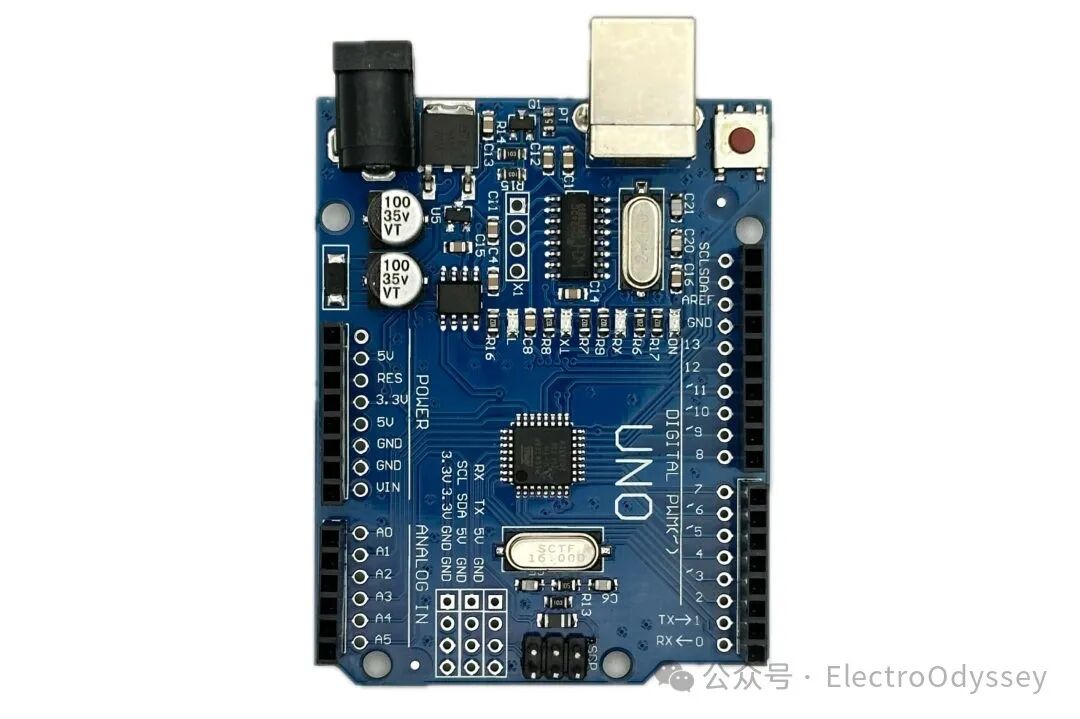
After completing the remote-controlled car project, I found the Arduino Nano development board to be very useful due to its small size. Most interfaces on the Arduino UNO require Dupont wires for connections, but the aging of the interfaces makes the 5V and GND power ports increasingly unreliable. Sometimes, I have to hold the development board to keep the 5V interface connected to power external devices properly.
The Arduino Nano connects directly to the breadboard via pin headers, allowing me to use ordinary wires to connect the development board to other modules. Another advantage of binding the Nano to the breadboard is that I can take all the devices with just a small breadboard. Otherwise, to pick up the entire setup, I would need to hold the UNO development board in one hand and the breadboard in the other, which is very inconvenient.
As for the remote control and accelerometer, reducing their size is even more important.
Ultimately, I used the Arduino Nano as the controller for this project.
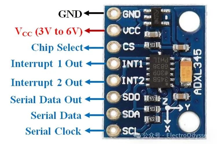
I found two models of accelerometers online: ADXL345 and MPU6050, both of which can sense acceleration in the xyz three-axis direction.
The difference between the two is that the MPU6050 is also equipped with a gyroscope sensor. The gyroscope can sense angular velocity in three axes, detecting the rotational part of the motion. If I want to recognize complex actions, this feature can provide more information for the program to make more accurate judgments.
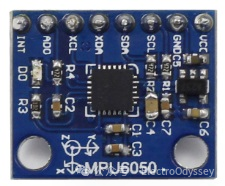
However, in this project, I only need to detect tilt direction and simple shaking, so I can make correct judgments without the gyroscope.
The ADXL345 three-axis accelerometer uses the I2C communication protocol, requiring two signal lines in addition to Vcc and GND for power. The SCL serial clock connects to the A5 pin of the development board, and the SDA serial data connects to the A4 pin.
After selecting the input components, the next step is to consider the output components.
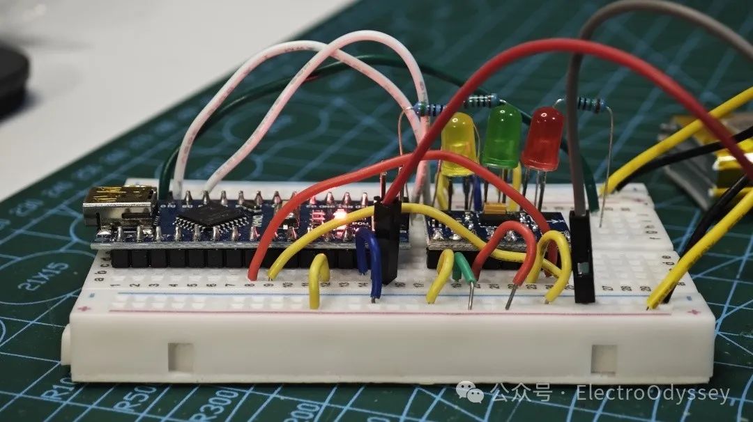
I chose red, green, and blue LEDs, connected them in series with a 150Ω current-limiting resistor, and then tested the brightness with a 5V power supply.
At the moment I plugged in the USB, all three LEDs lit up simultaneously, with the blue LED being so bright that I could hardly open my eyes. I immediately replaced it with a higher resistance current-limiting resistor to reduce its brightness.
After some trials, the blue LED finally emitted light at an appropriate brightness, but I still didn’t like its color. I removed the blue LED from the breadboard and replaced it with a warm yellow LED, achieving a color combination I preferred.
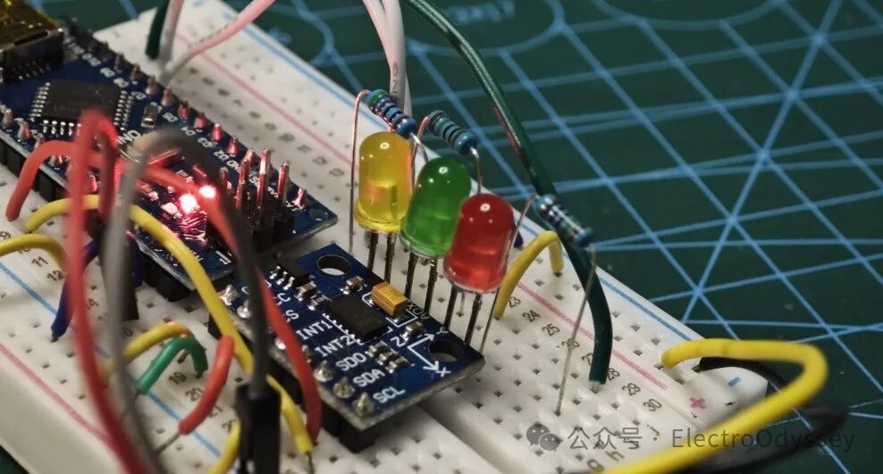
After testing, I connected the negative terminal of the LEDs to ground, and the positive terminals, through current-limiting resistors, to pins D9, D10, and D11 respectively. This way, the development board can directly control the three LEDs.
Software Programming
The I2C communication protocol used by the accelerometer took me back to a knowledge blind spot.
I tried using an existing accelerometer library, but I couldn’t get the functions in the library to work properly. Since I didn’t understand the underlying logic of the program, I couldn’t troubleshoot the errors. In desperation, I pulled out the code I copied from my last lantern project and tried to replicate it line by line.
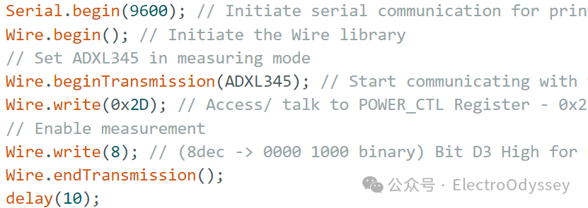
First, we need to initialize the I2C communication, then have the host send the sensor address, write register commands to the sensor, set the sensor’s operational state, and finally end the communication.
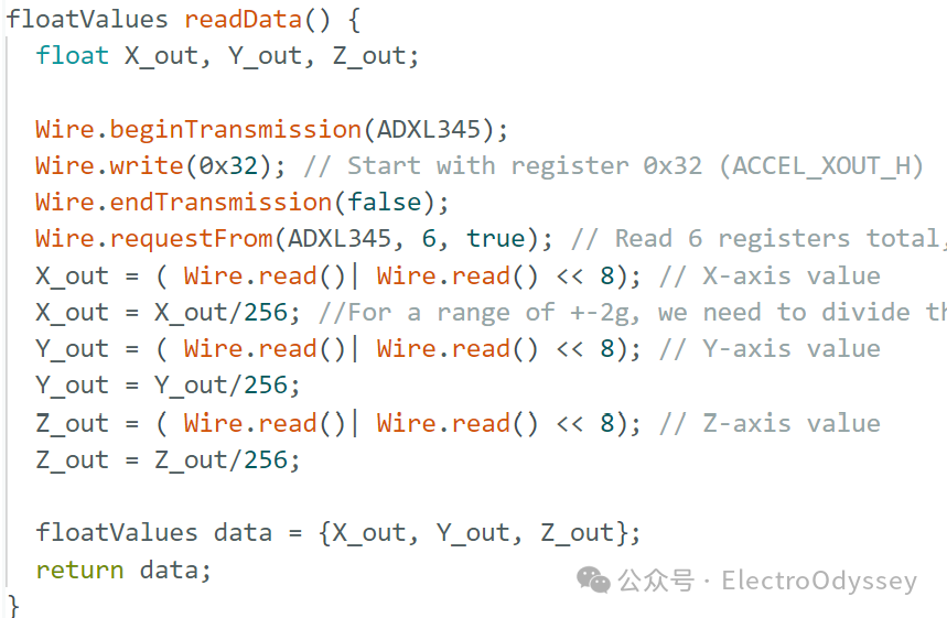
When reading data, the development board needs to send the sensor’s address and then read the acceleration from six registers corresponding to each coordinate.
As expected, I failed again. Although my program looked exactly like others’ code, subtle errors prevented my program from running correctly, and I couldn’t find out where the error was.
To keep the project moving forward, I gave up on my exploratory ideas and packaged others’ code into functions and included them in the main program. Even such a basic task took me over an hour to complete.
After reading the data, I could focus on the logical part of the program.
I placed the breadboard at different tilt angles while monitoring the data returned via the serial port. Based on the data corresponding to various postures, I could identify the thresholds for each tilt direction. Once I clarified my thoughts, I began writing and testing the program.
All I had to do was add one or two directions to the program, upload it for debugging, and try step by step. Eventually, I completed the classification of eight states using if-else statements, finishing this project.
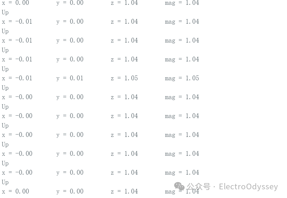
Results Display
One More Thing
If I undertake similar projects in the future, I might use mathematical methods to preprocess the data, calculating the magnitude of the acceleration vector and the angle between the vector and the coordinate axes.
This might reduce the difficulty of data processing.
References
Circuit Digest (Director). (2015, July 29). Accelerometer Based Gesture Controlled Robot using Arduino [Video recording]. https://www.youtube.com/watch?v=IEVK3PpQTho
Jon E. Froehlich (Director). (2019, June 6). Realtime Accelerometer-Based 3D Gesture Recognition Demo [Video recording]. https://www.youtube.com/watch?v=nnTyqCwYVbA