Click to Learn More ↑↑
Authors: Xia Shenlin, Wang Gang, Li Xuefeng
Institution:China Shipbuilding Industry Corporation, 725 Research Institute
Source: “Metal Processing (Thermal Processing)” Magazine
A certain equipment drive gear experienced tooth breakage during use. The gear is made of 20CrMn steel, with a heat treatment state of carburizing quenching and low-temperature tempering. The technical requirement for the carburized hardening layer depth is 0.7~1.4mm, tooth surface hardness is 56~60HRC, and gear roughness is grade 3.2. This article determines the cause of the gear fracture failure through macro and micro fracture morphology observation of the failed gear, combined with analysis of the chemical composition of the gear material, measurement of the carburizing hardening layer depth, and metallographic comparison of the failed gear area with other non-failed (same batch without fracture) gear areas.
1. Macro Analysis
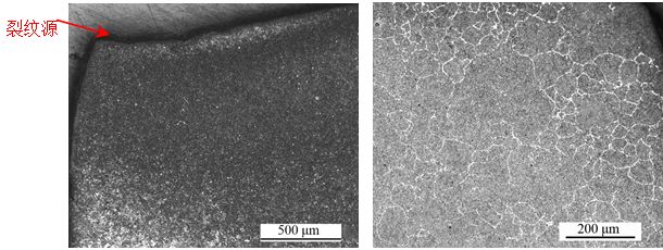
The macro fracture morphology of the failed tooth is shown in Figure 1. The failed tooth fractured from the root to the top, with the crack source originating at the root. The fracture surface is relatively flat, with no obvious plastic deformation characteristics, and there are evident beach marks near the crack source, indicating that the failure mode of this gear is preliminary identified as fatigue fracture. Visual inspection reveals that the surface processing quality of the gear is poor, with obvious machining marks on the root and tooth surface.
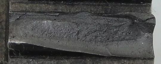
Figure 1 Macro Morphology of the Failed Tooth
2. Micro Fracture Observation
The fractured tooth was placed under an FEI Quanta 650FEG scanning electron microscope for micro fracture observation. The low magnification morphology of the fracture is shown in Figure 2a. The entire fracture is relatively flat, and no metallurgical defects such as slag inclusions, pores, or looseness were found. The morphology of the crack source area is shown in Figure 2b, located at the root of the tooth, where multiple step-like striations can be seen, indicating multiple sources with stress concentration. The morphology of the crack propagation area is shown in Figures 2c and 2d, where distinct fatigue striations are observed, mainly exhibiting fatigue characteristics, along with a small number of secondary cracks. Finally, the tearing area exhibits ductile dimple features, as shown in Figure 2e, and the area of the tearing zone occupies a small portion of the entire fracture area.
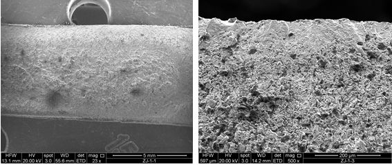
(a) Low Magnification Morphology (b) Crack Source Area Morphology
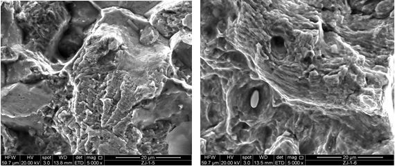
(c) Propagation Area Morphology (d) Magnified Propagation Area Morphology (Fatigue Characteristics)
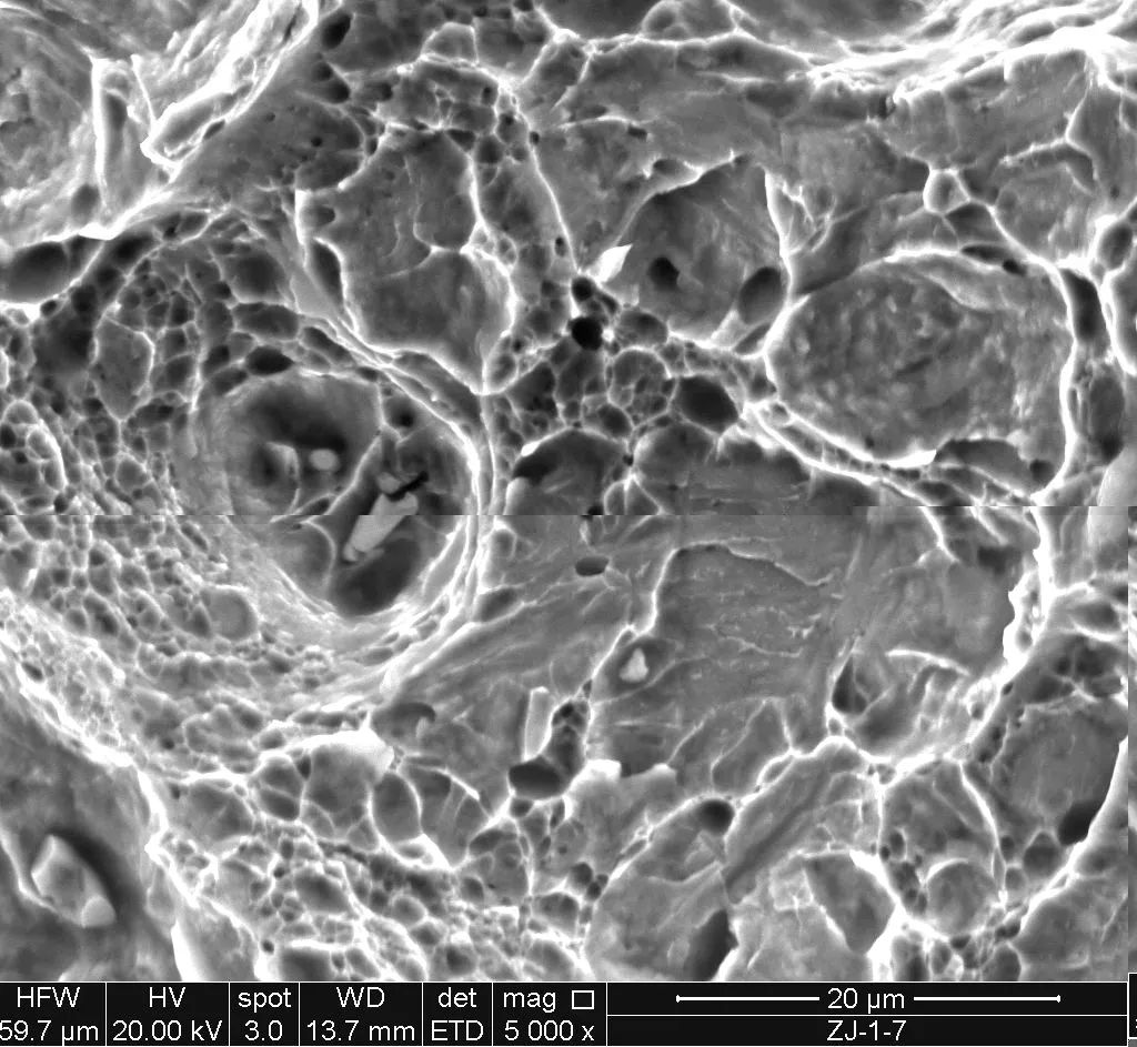
(e) Final Tearing Area Morphology
Figure 2 Micro Fracture Morphology
3. Chemical Composition
From the measured gear chemical composition and comparison with the GB/T 3077—2015 “Alloy Structural Steel” standard for 20CrMn steel composition requirements, it can be seen that the Si element content in the gear exceeds the standard requirements.
Chemical Composition of 20CrMn Steel Gear (Mass Fraction) (%)
|
Element |
C |
Mn |
Si |
Ni |
Cr |
Mo |
S |
P |
|
Measured Value |
0.227 |
1.00 |
0.29 |
0.025 |
1.01 |
0.018 |
0.0062 |
0.016 |
|
Standard Value |
0.17~0.23 |
0.9~1.2 |
0.17~0.23 |
≤0.03 |
0.9~1.2 |
— |
≤0.035 |
≤0.035 |
4. Carburizing Hardening Layer Depth Inspection
According to GB/T 9450—2005 “Determination and Verification of Effective Hardening Layer Depth of Carburized Steel Parts”, the effective hardening layer depth of the gear was inspected. A VMH-I04 micro Vickers hardness tester was used to measure the hardness from the tooth surface to the center, and the hardness gradient curve of the carburized hardening layer of the gear was plotted, with a test load of 0.49N (50gf) and loading time of 10s. Figure 3 shows the hardness gradient curve of the carburized hardening layer. From Figure 3, it can be seen that the effective hardening layer depth of the gear is approximately 1.2mm, which meets the technical requirement of 0.7~1.4mm.
The surface hardness of the carburized layer of the gear was measured using a Rockwell hardness tester, and the surface hardness of the carburized layer is approximately 61HRC, which meets the technical requirement of 56~62HRC for the carburized layer surface hardness.
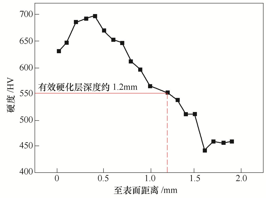
Figure 3 Hardness Gradient Curve of Carburized Hardening Layer
5. Microstructure
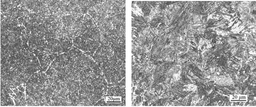
The metallographic structure of the failed gear and the non-failed gear was compared using an OLYMPUS GX 71 metallographic microscope. The metallographic structures of the failed gear and the non-failed gear samples after 4% nitric acid alcohol etching are shown in Figures 4 and 5, respectively. From Figure 4, it can be seen that the metallographic structure near the crack source of the failed gear is high-carbon martensite with network carbides distributed along the grain boundaries, and the closer to the surface, the coarser the network carbides; according to GB/T 25744—2010 “Metallographic Inspection of Carburized and Tempered Steel Parts”, referring to Appendix B for carbide grading, the network carbide grade is 3.0. The core structure of the failed gear is low-carbon martensite with a small amount of ferrite.
Figure 5 shows the metallographic structure of the non-failed gear, with the metallographic structure near the surface at the root being high-carbon martensite and granular carbides, with no network carbides observed (see Figure 5a); the core structure is low-carbon martensite with ferrite (see Figure 5b).
(a) Near the Crack Source (25×) (b) Near the Crack Source (100×)
(c) Near the Crack Source (500×) (d) Core (500×)
Figure 4 Metallographic Structure of the Failed Gear
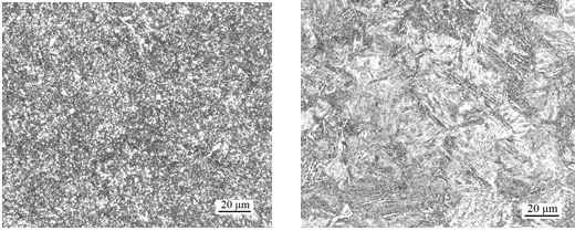
(a) Near the Root Surface (500×) (b) Core (500×)
Figure 5 Metallographic Structure of the Non-Failed Gear
6. Analysis and Discussion
The effective hardening layer depth of the gear is approximately 1.2mm, which meets the technical requirement of 0.7~1.4mm. The surface hardness of the carburized layer of the gear is approximately 61 HRC, which meets the technical requirement of 56~62 HRC for the carburized layer surface hardness.
The chemical composition of the gear does not comply with the GB/T 3077—2015 “Alloy Structural Steel” standard for 20CrMn steel composition requirements, as the Si element content exceeds standard requirements. The chemical composition of the steel has a certain impact on the surface quality of the parts. Studies show that excessive Si can reduce the surface quality of the tooth hardening layer, leading to oxidation of the grain boundaries in the surface layer, thus reducing the fatigue life of the gear.
From the macro observation of the fracture, it can be seen that the crack source originates at the root of the tooth, and the fracture surface is relatively flat, with no obvious plastic deformation characteristics and evident beach marks near the crack source; combined with micro fracture observations, fatigue striations can be seen, indicating that the failure mode of this gear is fatigue fracture. In addition, the entire fracture is relatively flat, with no metallurgical defects such as slag inclusions, pores, or looseness found.
The results of the metallographic analysis show that there are network carbides distributed along the grain boundaries near the crack source of the failed gear, and the closer to the surface, the coarser the network carbides. Compared with the metallographic structure of the non-failed gear (where carbides are distributed in small granular forms), the presence of network carbides in the failed gear is an abnormal structure caused by improper carburizing process. This network carbide, due to its brittleness and weak bonding strength with the matrix, hinders the continuity between the matrix, easily causing material embrittlement and reduced plasticity, thereby lowering fatigue strength. Moreover, the poor surface processing quality of the gear, with evident machining marks on the root, serves as pre-existing fatigue cracks, which has an extremely adverse effect on the total fatigue life of the gear.
In summary, the failure mode of the equipment drive gear is fatigue fracture, with the fatigue source starting at the root of the gear. On one hand, the rough surface processing near the root leads to stress concentration and the generation of fatigue cracks; on the other hand, improper carburizing process treatment results in the formation of network carbides distributed along the grain boundaries near the surface, increasing material brittleness and reducing fatigue strength; under cyclic loading, this leads to gear failure and fracture.

Business Cooperation: 13501198334
Hot Topics ↓↓Read the Original Text↙↙