The goal of this article is to develop an inertial navigation system for a wheeled robot, capable of controlling the robot’s movements and transmitting data collected by the robot through Wi-Fi to a PC terminal and a handheld terminal.
Build the system shown in Figure 1, with a DSP chip acting as the main digital signal processor, collecting signals from various MEMS inertial sensors and processing them. The processed results are transmitted to the PC terminal via Wi-Fi; the PC terminal is responsible for displaying positioning results and map display, sending control commands to the robot’s drive system, and receiving odometer information feedback from the drive system.
In terms of hardware design, it mainly consists of a core board and a drive board. The core board includes the DSP minimal system, JTAG download port design, system power supply circuit, MEMS sensors, Wi-Fi module, etc. The drive board primarily focuses on designing the DC motor drive module.
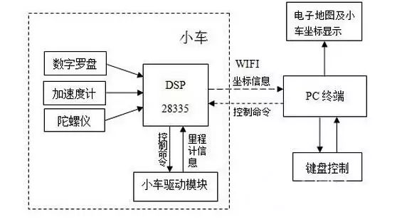
Figure 1 Overall Architecture
Power Supply Circuit Design
The TMS320F28335 requires different voltages during operation: core voltage (1.9 V) and I/O power supply voltage (3.3 V). It is sensitive to power supply, so the power supply part uses two output power devices TPS767D318 to achieve this, as shown in Figure 2. Meanwhile, based on simulation experiments and actual soldering circuit tests, it is best to use some protective capacitors with values no less than 10uF at the output end of the power module, and surface mount capacitors should not be used; otherwise, the operation will be unstable.
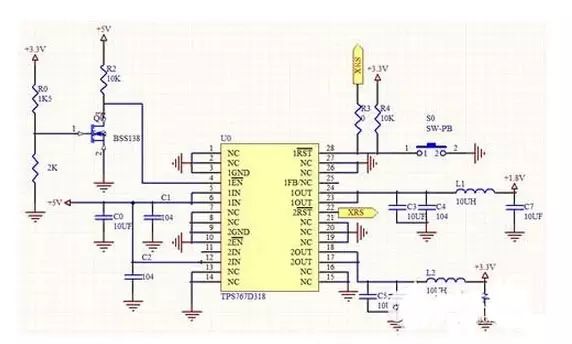
Figure 2 DSP Power Design
In the power supply design, considering that the TPS767D318 chip can generate a reset signal, no additional reset circuit for the DSP is designed on the core board.
JTAG Download Port Circuit Design
Figure 3 shows the JTAG circuit, where the 14-pin emulation interface is selected according to the communication pins of the emulator. It is important to note that the EMU0 and EMU1 signals must be connected to the power supply through pull-up resistors, with the pull-up resistor being 10kΩ.
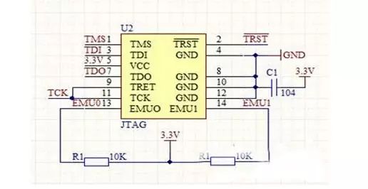
Figure 3 JTAG Circuit Design
Robot Drive Board Design
In this device, we use BTS7960 as the DC motor driver chip. BTS7960 is an integrated high-current half-bridge driver, which internally contains one NMOS, one PMOS, and one half-bridge gate driver. At IOUT = 9 A, VS = 13.5V, and Tj = 25 °C, its internal resistance is 17mΩ. The device uses two DC large motors, as shown in Figure 4 for the circuit diagram driving a single motor’s forward and backward direction.
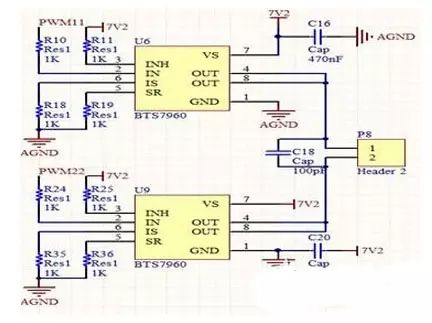
Figure 4 Drive Module Circuit Design
In motor driving, it is important to note that the motor may generate back electromotive force during rotation, which can cause a sudden increase in current, leading to a reset of the microcontroller or even damaging the chip. Therefore, during the design process, consider adding an opto-isolator or diode at the point where the microcontroller’s PWM input connects to the motor drive interface. As shown in Figure 5, the drive board uses the TLP521-4 opto-isolator to design the isolation circuit, reducing voltage interference and simplifying circuit design, while also pulling the I/O level of four PWM signals from 3.3V to 5V.
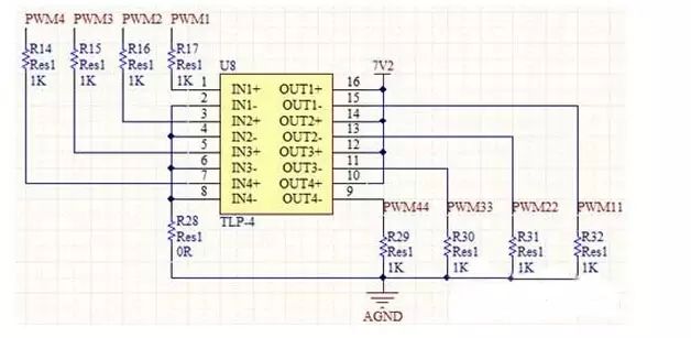
Figure 5 TLP521 Isolation Circuit
The indoor inertial navigation device for the wheeled robot designed in this article analyzes the specific implementation methods of various modules in the software design. Experimental results show that this design can monitor the position information of the mobile robot in real-time and effectively control it. Moreover, its characteristics of low cost, high precision, and easy operation will further apply to professional fields such as patrol robots and rescue robots, which will undoubtedly attract numerous investors both domestically and internationally for investment and further R&D and application, giving it a vast prospect for innovation, entrepreneurship, and market application.