“Assembly Language”, 3rd Edition by Wang Shuang
Chapter 13: int Instruction (Page 262)
Experiment 13: Writing and Applying Interrupt Routines
————————————
Note: This is the code example and analysis for Experiment 13, Question 2.
———————————–
(2) Write and install the int 7cH interrupt routine, which implements the functionality of the loop instruction.
Parameters: (cx) = number of loops, (bx) = displacement.
Requirement: After successfully installing the above interrupt routine, perform single-step tracing on the following program, paying special attention to the state of CS, IP, and the stack before and after executing the int and iret instructions.
Test Program: Display 80 “!” characters in the center of the screen.
assume cs:codecode segment start: mov ax, 0b800H mov es, ax mov di, 160*12 mov bx, offset s - offset se ; Calculate the displacement from se to s mov cx, 80 s: mov byte ptr es:[di], '!' add di, 2 int 7cH ; If (cx) ≠ 0, jump to s se: nop mov ax, 4c00H int 21Hcode endsend start ====================
The analysis is as follows:
In section 13.3 (Page 256), Professor Wang Shuang discusses how to simulate the loop instruction, providing key explanations and code implementations. Here, we only need to write an installation program to install the 7cH interrupt routine that simulates the loop functionality at address 0:200H.
The example code is as follows:
; "Assembly Language", 3rd Edition by Wang Shuang; Chapter 13: int Instruction (Page 251); Experiment 13: Writing and Applying Interrupt Routines; (2) Write and install the 7cH interrupt routine to implement the loop instruction functionality
assume cs:codecode segment           ; Copy the machine code of the 7cH interrupt routine to 0:200H    start: mov ax, code           mov ds, ax           mov si, offset int7c_begin           mov ax, 0           mov es, ax           mov di, 200H           mov cx, offset int7c_end - offset int7c_begin           cld           rep movsb           ; Set the 7cH interrupt vector to point to 0:200H           mov ax, 0           mov es, ax           mov word ptr es:[7cH*4], 200H           mov word ptr es:[7cH*4+2], 0           ; Installation complete, return           mov ax, 4c00H           int 21H                 ; 7cH interrupt routine, implements the loop instruction functionality    int7c_begin: push bp                 mov bp, sp                 dec cx                 jcxz int7c_ret                 add [bp+2], bx  ; bp default segment address is SS      int7c_ret: pop bp                 iret      int7c_end: nop            code endsend start
The debugging trace process is as follows:
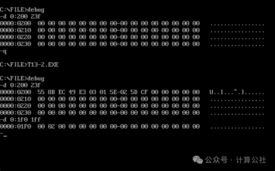
1. Test the installation program for the 7cH interrupt routine, as shown in the figure below. Before installation, the data at 0:200H is all 0. After executing the installation program, the 7cH interrupt routine code is copied to 0:200H, and the 7cH interrupt vector (7cH*4=1F0H) is also updated to 0000:0200. The installation of the 7cH interrupt routine is successful.
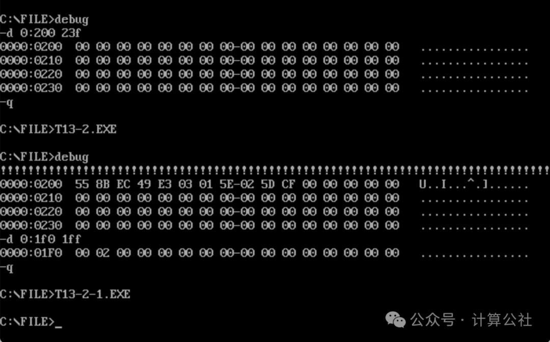
2. After the 7cH is installed, run the test program directly, and you can see 80 “!” characters displayed on the screen, as shown in the figure below. The test passed.
3. Perform single-step tracing debugging according to the requirements of the question, which should be exactly the same as in Experiment (1). The specific tracing process is not included here; if needed, please refer to Experiment (1).