(Add a star to BoLe Online to see classic articles)
Source: Ruheng
Link: https://juejin.im/post/6844903490595061767
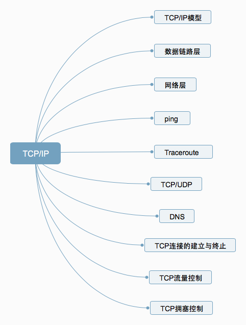
1. TCP/IP Model
The TCP/IP protocol model (Transmission Control Protocol/Internet Protocol) consists of a series of network protocols that form the foundation of the Internet and is the core protocol of the Internet.The reference model based on TCP/IP divides the protocols into four layers: the Link Layer, the Network Layer, the Transport Layer, and the Application Layer. The diagram below shows the correspondence between the TCP/IP model and the OSI model layers.

The TCP/IP protocol suite is layered from top to bottom, with each layer encapsulating the one below it. The topmost layer is the Application Layer, which includes familiar protocols such as HTTP and FTP. The second layer is the Transport Layer, where the well-known TCP and UDP protocols reside. The third layer is the Network Layer, where the IP protocol is located, responsible for adding IP addresses and other data to determine the transmission target. The fourth layer is the Data Link Layer, which adds an Ethernet protocol header to the data to be transmitted and performs CRC encoding to prepare for the final data transmission.
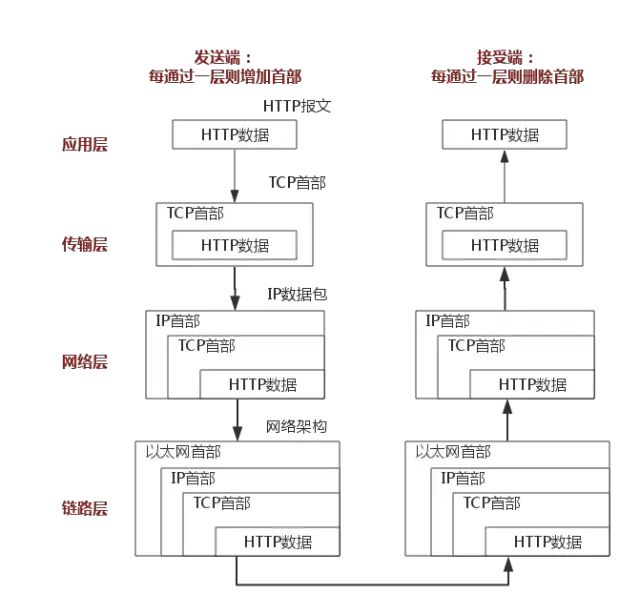
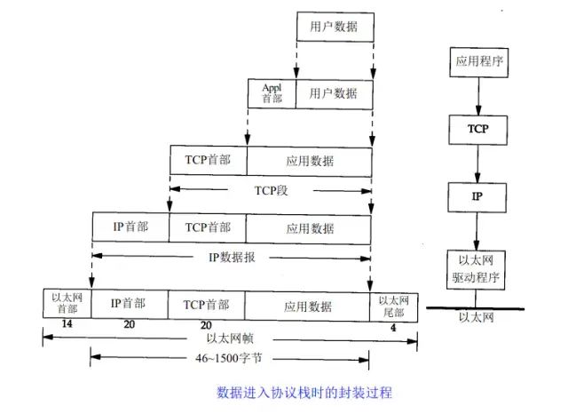 The above diagram clearly illustrates the role of each layer in the TCP/IP protocol, and the communication process of the TCP/IP protocol corresponds to the process of data being pushed onto and popped off the stack. During the push process, the sender continuously encapsulates headers and trailers at each layer, adding transmission information to ensure it reaches the destination. During the pop process, the receiver continuously removes headers and trailers at each layer to obtain the final transmitted data.
The above example uses the HTTP protocol for a detailed explanation.
2. Data Link Layer
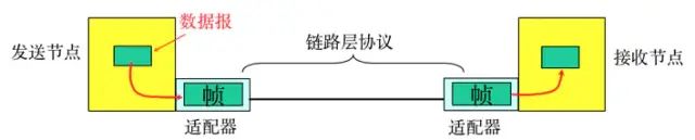
The Physical Layer is responsible for the conversion between the 0s and 1s bit stream and the physical device’s voltage levels and light states. The Data Link Layer is responsible for dividing the 0s and 1s sequence into data frames for transmission from one node to a neighboring node, which are uniquely identified by MAC addresses (MAC, physical address, each host has a MAC address).
-
Frame encapsulation: The network layer datagram is encapsulated into a frame by adding headers and trailers, with the frame header including the source MAC address and destination MAC address.
-
Transparent transmission: Zero-bit padding, escape characters.
-
Reliable transmission: Rarely used on low-error-rate links, but wireless links (WLAN) ensure reliable transmission.
-
Error detection (CRC): The receiver checks for errors, and if an error is detected, the frame is discarded.
3. Network Layer
1. IP Protocol
The IP protocol is the core of the TCP/IP protocol, and all TCP, UDP, ICMP, and IGMP data is transmitted in IP data format. It is important to note that IP is not a reliable protocol, meaning it does not provide a mechanism for handling undelivered data, which is the responsibility of upper-layer protocols: TCP or UDP.
1.1 IP Address
In the Data Link Layer, we generally identify different nodes by MAC addresses, while in the IP layer, we also need a similar address identifier, which is the IP address.
A 32-bit IP address is divided into a network part and a host part, which reduces the number of entries in the routing table of routers. With the network address, terminals with the same network address can be limited to the same range, allowing the routing table to maintain only one direction for that network address to find the corresponding terminals.Class A IP address: 0.0.0.0~127.0.0.0Class B IP address: 128.0.0.1~191.255.0.0Class C IP address: 192.168.0.0~239.255.255.0
1.2 IP Protocol Header

Here we only introduce the eight-bit TTL field. This field specifies how many routers the packet can pass through before being discarded. Each time an IP packet passes through a router, the TTL value decreases by 1, and when the TTL becomes zero, the packet is automatically discarded.
The maximum value of this field is 255, meaning a protocol packet can pass through a router 255 times before being discarded. Depending on the system, this number may vary, typically being 32 or 64.
2. ARP and RARP Protocols
ARP is a protocol for obtaining MAC addresses based on IP addresses.The ARP (Address Resolution Protocol) is a resolution protocol; originally, the host does not know which interface corresponds to the IP address. When a host wants to send an IP packet, it first checks its ARP cache (which is an IP-MAC address mapping cache).If the queried IP-MAC pair does not exist, the host sends an ARP broadcast packet to the network, which contains the IP address to be queried. All hosts that receive this broadcast will check their IP addresses, and if a host finds that it matches the condition, it prepares an ARP packet containing its MAC address to send back to the host that sent the ARP broadcast.After the broadcasting host receives the ARP packet, it updates its ARP cache (which stores the IP-MAC mapping). The broadcasting host will then use the new ARP cache data to prepare the data link layer packet for transmission.The RARP protocol works in the opposite manner and will not be elaborated here.
3. ICMP Protocol
The IP protocol is not a reliable protocol; it does not guarantee data delivery. Therefore, the responsibility for ensuring data delivery should fall to other modules. One important module is the ICMP (Internet Control Message Protocol). ICMP is not a high-level protocol but rather a protocol at the IP layer.
When errors occur in the transmission of IP packets, such as host unreachable or route unreachable, the ICMP protocol will encapsulate the error information and send it back to the host, giving the host a chance to handle the error. This is why it is said that protocols built on top of the IP layer can potentially be secure.
4. Ping
Ping can be considered the most famous application of ICMP and is part of the TCP/IP protocol. The “ping” command can check whether the network is connected and can help us analyze and determine network faults effectively.
For example, when we cannot access a certain website, we usually ping that website. The ping command will echo some useful information. The general information is as follows:
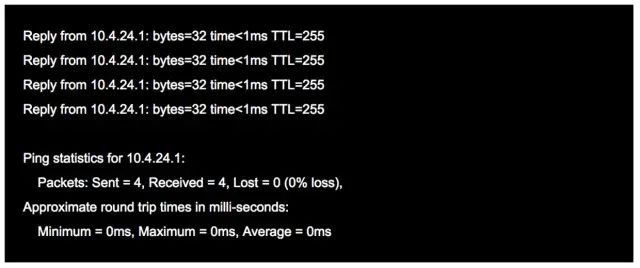
The word ping comes from sonar positioning, and this program indeed serves that purpose; it uses ICMP packets to detect whether another host is reachable. The principle is to send a request using an ICMP packet with a type code of 0, and the responding host replies with an ICMP packet of type code 8.
5. Traceroute
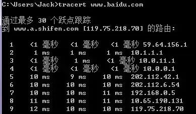
Traceroute is an important tool for detecting the routing situation between a host and the destination host, and it is also one of the most convenient tools.
The principle of Traceroute is very interesting. After receiving the destination host’s IP, it first sends a UDP packet with TTL=1 to the destination host. The first router that receives this packet automatically decreases the TTL by 1, and when the TTL becomes 0, the router discards the packet and generates an ICMP message indicating that the host is unreachable. The host then sends a UDP packet with TTL=2 to the destination host, prompting the second router to send an ICMP message back to the host. This process continues until the destination host is reached. In this way, Traceroute obtains the IP addresses of all the routers along the path.
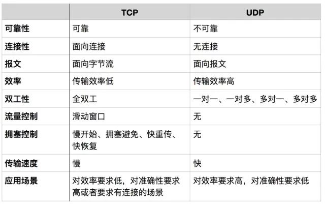
6. TCP/UDP
TCP and UDP are both transport layer protocols, but they have different characteristics and applications. The following table compares and analyzes them.
Message-oriented
In message-oriented transmission, the application layer specifies the length of the message to UDP, and UDP sends it as is, sending one message at a time. Therefore, the application must choose an appropriate message size. If the message is too long, the IP layer needs to fragment it, reducing efficiency. If it is too short, it may be too small for IP.
Byte stream-oriented
In byte stream-oriented transmission, although the application interacts with TCP one data block at a time (of varying sizes), TCP treats the application as a continuous stream of unstructured bytes. TCP has a buffer, and when the data block sent by the application is too long, TCP can break it into shorter segments for transmission.Congestion control and flow control are key aspects of TCP, which will be explained later.Some applications of TCP and UDP
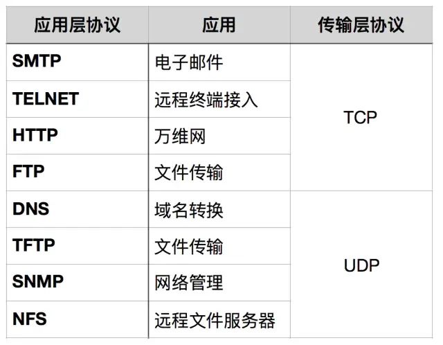
When should TCP be used?
When there are quality requirements for network communication, such as ensuring that all data is accurately transmitted to the other party, this is often used for applications that require reliability, such as HTTP, HTTPS, FTP for file transfers, and POP, SMTP for email transmission.
When should UDP be used?
When there are no high requirements for network communication quality, and speed is prioritized, UDP can be used.
7. DNS
DNS (Domain Name System) is a distributed database on the Internet that maps domain names to IP addresses, allowing users to access the Internet more conveniently without having to remember IP address strings that can be read directly by machines. The process of obtaining the IP address corresponding to a hostname through the hostname is called domain name resolution (or hostname resolution). The DNS protocol operates over UDP, using port number 53.
8. Establishing and Terminating TCP Connections
1. Three-Way Handshake
TCP is connection-oriented, meaning that before either party can send data, a connection must first be established between both parties. In the TCP/IP protocol, the TCP protocol provides reliable connection services, and the connection is initialized through a three-way handshake. The purpose of the three-way handshake is to synchronize the sequence numbers and acknowledgment numbers of both parties and exchange TCP window size information.
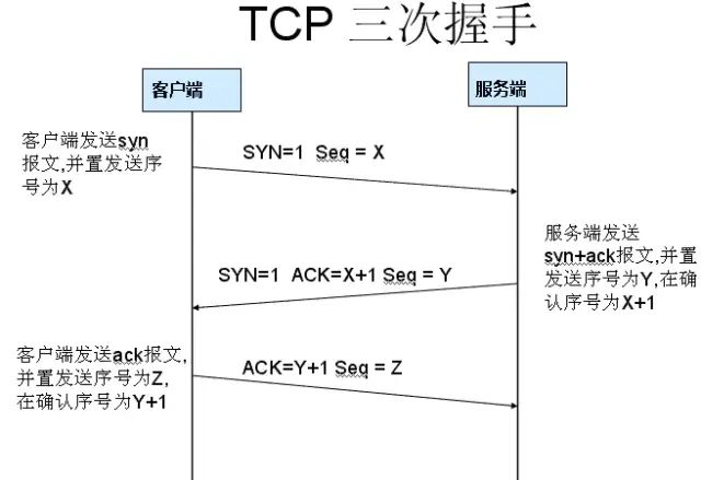
First handshake: Establishing the connection. The client sends a connection request segment, setting SYN to 1 and Sequence Number to x; then, the client enters the SYN_SEND state, waiting for the server’s acknowledgment;
Second handshake: The server receives the SYN segment. The server acknowledges the client’s SYN segment by setting the Acknowledgment Number to x+1 (Sequence Number+1); at the same time, it sends its own SYN request, setting SYN to 1 and Sequence Number to y; the server puts all this information into a segment (i.e., SYN+ACK segment) and sends it to the client, entering the SYN_RECV state;Third handshake: The client receives the server’s SYN+ACK segment. It then sets the Acknowledgment Number to y+1 and sends an ACK segment to the server. After this segment is sent, both the client and server enter the ESTABLISHED state, completing the TCP three-way handshake.
Why three-way handshake?
To prevent a stale connection request segment from suddenly being sent to the server, causing errors.
A specific example of a “stale connection request segment” occurs in a situation where the first connection request segment sent by the client is not lost but is delayed at a network node for a long time, arriving at the server after the connection has been released. This is a segment that has already become invalid. However, when the server receives this stale connection request segment, it mistakenly believes it is a new connection request from the client.Thus, it sends an acknowledgment segment to the client, agreeing to establish a connection. If the “three-way handshake” is not used, as soon as the server sends the acknowledgment, a new connection would be established. Since the client has not sent a connection establishment request, it will not respond to the server’s acknowledgment and will not send data to the server. However, the server would think a new transport connection has been established and would be waiting for the client to send data. This would waste many of the server’s resources. The “three-way handshake” method can prevent this phenomenon. For example, in the situation described above, the client would not send an acknowledgment to the server’s acknowledgment. The server, not receiving the acknowledgment, would know that the client did not request to establish a connection.
2. Four-Way Handshake
After the client and server establish a TCP connection through the three-way handshake, when the data transmission is complete, the TCP connection must be terminated. This is where the mysterious “four-way handshake” comes into play.
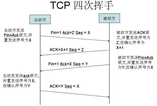
First handshake: Host 1 (which can be either the client or the server) sets the Sequence Number and sends a FIN segment to Host 2; at this point, Host 1 enters the FIN_WAIT_1 state; this indicates that Host 1 has no data to send to Host 2;
Second handshake: Host 2 receives the FIN segment sent by Host 1 and sends an ACK segment back to Host 1, with the Acknowledgment Number set to the Sequence Number plus 1; Host 1 enters the FIN_WAIT_2 state; Host 2 informs Host 1 that it “agrees” to the close request;
Third handshake: Host 2 sends a FIN segment to Host 1, requesting to close the connection, while Host 2 enters the LAST_ACK state;
Fourth handshake: Host 1 receives the FIN segment sent by Host 2 and sends an ACK segment back to Host 2, then Host 1 enters the TIME_WAIT state; after Host 2 receives Host 1’s ACK segment, it closes the connection; at this point, Host 1 waits for 2 MSL (Maximum Segment Lifetime) and if it still does not receive a reply, it confirms that the server has closed normally, and then Host 1 can also close the connection.
Why four-way handshake?
The TCP protocol is a connection-oriented, reliable, byte-stream-based transport layer communication protocol. TCP operates in full-duplex mode, which means that when Host 1 sends a FIN segment, it only indicates that Host 1 has no more data to send; Host 1 informs Host 2 that it has finished sending all its data. However, at this point, Host 1 can still receive data from Host 2. When Host 2 returns the ACK segment, it indicates that it knows Host 1 has no data to send, but Host 2 can still send data to Host 1. When Host 2 also sends a FIN segment, it indicates that Host 2 also has no data to send, and it will inform Host 1 that it also has no data to send, after which both parties will happily terminate this TCP connection.
Why wait for 2 MSL?
MSL: Maximum Segment Lifetime, which is the longest time any segment can remain in the network before being discarded. There are two reasons:
-
To ensure that the TCP protocol’s full-duplex connection can be reliably closed.
-
To ensure that any duplicate data segments from this connection disappear from the network.
The first point: If Host 1 directly goes to CLOSED, and due to the unreliability of the IP protocol or other network reasons, Host 2 does not receive Host 1’s final ACK reply. Then Host 2 will continue to send FIN after a timeout, and since Host 1 has already CLOSED, it will not find a corresponding connection for the retransmitted FIN. Therefore, Host 1 does not directly enter CLOSED but remains in TIME_WAIT, so that when it receives FIN again, it can ensure that the other party receives the ACK and finally closes the connection correctly.
The second point: If Host 1 directly goes to CLOSED and then initiates a new connection to Host 2, we cannot guarantee that the new connection will have a different port number from the recently closed connection. This means that it is possible for the new connection and the old connection to have the same port number. Generally, this will not cause any problems, but there are special cases: if the new connection and the already closed old connection have the same port number, and some data from the previous connection is still lingering in the network, this delayed data may arrive at Host 2 after the new connection is established. Since the new connection and the old connection have the same port number, the TCP protocol will consider that delayed data to belong to the new connection, which can confuse it with the actual data packets of the new connection. Therefore, the TCP connection must remain in the TIME_WAIT state for 2 MSL to ensure that all data from this connection disappears from the network.
9. TCP Flow Control
If the sender sends data too quickly, the receiver may not be able to keep up, leading to data loss. Flow control is about ensuring that the sender’s transmission rate is not too fast, allowing the receiver to keep up.
Using the sliding window mechanism can conveniently implement flow control on a TCP connection.
Assuming A sends data to B. At the time of connection establishment, B informs A: “My receive window is rwnd = 400” (where rwnd represents the receiver window). Therefore, the sender’s sending window cannot exceed the value given by the receiver’s window. Note that the TCP window is measured in bytes, not segments. Assuming each segment is 100 bytes long, and the initial value of the data segment sequence number is set to 1. Uppercase ACK indicates the acknowledgment bit in the header, while lowercase ack indicates the acknowledgment field value.
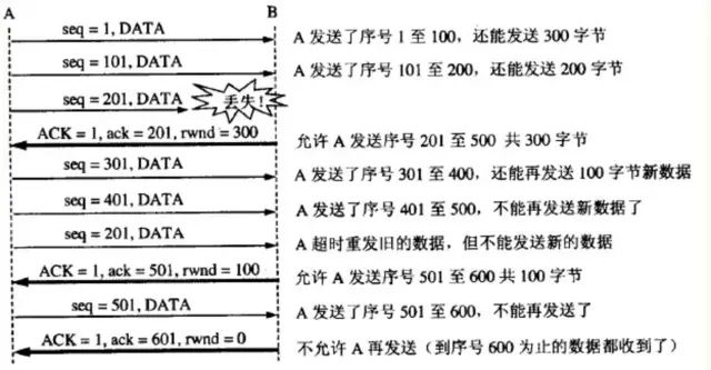
From the diagram, it can be seen that B performs flow control three times. The first time it reduces the window to rwnd = 300, the second time to rwnd = 100, and finally to rwnd = 0, meaning the sender is not allowed to send any more data. This state of pausing the sender will last until Host B sends a new window value.
TCP sets a persistence timer for each connection. As long as one side of the TCP connection receives a zero window notification from the other side, it starts the persistence timer. If the persistence timer expires, it sends a zero window probe segment (carrying 1 byte of data), and the party receiving this segment resets the persistence timer.
10. TCP Congestion Control
The sender maintains a congestion window (cwnd) state variable. The size of the congestion window depends on the level of network congestion and changes dynamically. The sender sets its sending window equal to the congestion window.
The principle of controlling the congestion window is: as long as there is no congestion in the network, the congestion window increases to allow more packets to be sent. However, if congestion occurs, the congestion window decreases to reduce the number of packets injected into the network.
Slow start algorithm:
When a host starts sending data, if a large amount of data is injected into the network immediately, it may cause network congestion, as the load situation of the network is not yet clear. Therefore, a better method is to probe first, that is, gradually increase the sending window from small to large, meaning gradually increase the congestion window value.
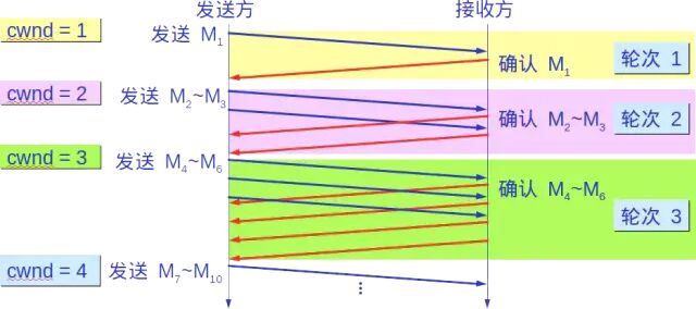
Typically, when starting to send segments, the congestion window (cwnd) is set to the value of one Maximum Segment Size (MSS). After receiving an acknowledgment for each new segment, the congestion window is increased by at most one MSS. This method of gradually increasing the sender’s congestion window (cwnd) allows packets to be injected into the network at a more reasonable rate.
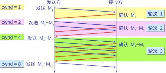
After each transmission round, the congestion window (cwnd) doubles. The time for one transmission round is actually the round-trip time (RTT). However, the term “transmission round” emphasizes that all segments allowed to be sent by the congestion window (cwnd) are sent continuously and that the acknowledgment for the last byte sent is received.
Additionally, the “slow” in slow start does not refer to the slow growth rate of cwnd, but rather that at the beginning of TCP segment transmission, cwnd is set to 1, allowing the sender to send only one segment at the start (to probe the network’s congestion situation) before gradually increasing cwnd.
To prevent the congestion window (cwnd) from growing too large and causing network congestion, a slow start threshold (ssthresh) state variable is also set. The usage of the slow start threshold (ssthresh) is as follows:
-
When cwnd < ssthresh, use the above slow start algorithm.
-
When cwnd > ssthresh, stop using the slow start algorithm and switch to the congestion avoidance algorithm.
-
When cwnd = ssthresh, either the slow start algorithm or the congestion avoidance algorithm can be used.
Congestion avoidance
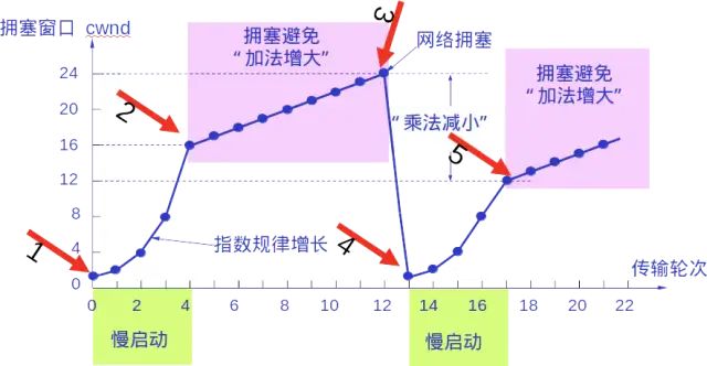
Allows the congestion window (cwnd) to increase slowly, that is, increase the sender’s congestion window (cwnd) by 1 for each round-trip time (RTT), rather than doubling it. This way, the congestion window (cwnd) grows slowly in a linear manner, much slower than the growth rate of the congestion window in the slow start algorithm.
Whether in the slow start phase or the congestion avoidance phase, as long as the sender determines that network congestion has occurred (based on the lack of received acknowledgments), it must set the slow start threshold (ssthresh) to half of the sender’s window value at the time of congestion (but not less than 2). Then, the congestion window (cwnd) is reset to 1, and the slow start algorithm is executed.
The purpose of this is to quickly reduce the number of packets sent into the network, allowing the congested router enough time to process the packets queued up.
The following diagram illustrates the process of congestion control with specific values. Now the size of the sending window is equal to that of the congestion window.
2. Fast Retransmit and Fast Recovery
Fast Retransmit
The fast retransmit algorithm requires the receiver to immediately send a duplicate acknowledgment for each out-of-order segment received (to allow the sender to know early that a segment has not reached the other party) rather than waiting until it sends data to send the acknowledgment.
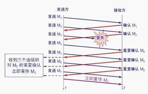
Assuming the receiver has received M1 and M2 and has sent acknowledgments for them. Now suppose the receiver has not received M3 but has received M4.
Clearly, the receiver cannot acknowledge M4 because it is an out-of-order segment. According to the reliable transmission principle, the receiver can either do nothing or send a duplicate acknowledgment for M2 at an appropriate time.
However, according to the fast retransmit algorithm, the receiver should promptly send a duplicate acknowledgment for M2, allowing the sender to know early that segment M3 has not reached the receiver. The sender then sends M5 and M6. After the receiver receives these two segments, it must again send a duplicate acknowledgment for M2. In this way, the sender receives four acknowledgments for M2 from the receiver, three of which are duplicate acknowledgments.
The fast retransmit algorithm also stipulates that as soon as the sender receives three duplicate acknowledgments, it should immediately retransmit the unacknowledged segment M3 without waiting for the retransmission timer for M3 to expire.
By retransmitting unacknowledged segments early, the overall network throughput can be improved by about 20% with the fast retransmit.
Fast Recovery
Fast recovery is used in conjunction with fast retransmit and has the following two key points:
-
When the sender receives three consecutive duplicate acknowledgments, it executes the “multiplicative decrease” algorithm, halving the slow start threshold (ssthresh). Unlike slow start, the slow start algorithm is not executed now (i.e., the congestion window (cwnd) is not set to 1), but rather the cwnd value is set to the value of the slow start threshold (ssthresh) after halving, and then the congestion avoidance algorithm (“additive increase”) is executed, allowing the congestion window to increase slowly in a linear manner.
– EOF –
Recommended Reading Click the title to jump
1. It is said that programmers think about scheduling algorithms while waiting for the elevator, and netizens: really?
2. How “terrifying” is it for programmers to take care of children?!
3. Comparable to a 007 movie! Finding the precise location of the photographer through a photo
Did you gain something from this article? Please share it with more people
Recommended to follow “BoLe Online” for selected IT career articles
Likes and views are the biggest support ❤️