An Energy-Efficient Multi-Channel MAC Protocol for Linear Sensor Networks

An Energy-Efficient Multi-Channel MAC Protocol for Linear Sensor Networks

An Energy-Efficient Multi-Channel MAC Protocol for Linear Sensor Networks

Click the blue text above to follow us!

An Energy-Efficient Multi-Channel MAC Protocol for Linear Sensor Networks

Tong Fei1,2,3, Sui Rucong1, Chen Yu1, Su Heng1, Liu Hengrui1, Su Shangfeng1, Yan Yuke1

1. Southeast University, School of Cyberspace Security, Nanjing, Jiangsu 211189;

2. Jiangsu Provincial Ubiquitous Network Security Engineering Research Center, Nanjing, Jiangsu 211189; 3. Network Communication and Security Zijinshan Laboratory, Nanjing, Jiangsu 211111

Abstract:

In a linear sensor network (LSN), sensor nodes are deployed linearly due to the linear topology of the monitored area. The existing duty-cycling and pipelined-forwarding (DCPF) medium access control (MAC) protocols used for LSN can reduce packet transmission delay and decrease network energy consumption. However, they still face competition, interference during packet transmission, and energy hole problems. To address this, we propose an improved DCPF protocol based on multi-channel and redundant node deployment. Simulation results based on OPNET show that the proposed protocol performs better than existing protocols in terms of energy efficiency, packet arrival rate, throughput, and packet transmission delay.

Keywords:Linear Sensor Network; Redundant Node; Transmission Interference; Energy Hole; Duty-Cycling Scheduling; Multi-Channel

Citation Format:

Tong Fei, Sui Rucong, Chen Yu, et al. An energy-efficient multi-channel MAC protocol for linear sensor networks[J]. Chinese Journal on Internet of Things, 2022, 6(4): 27-40.

TONG F, SUI R C, CHEN Y, et al. An energy-efficient multi-channel MAC protocol for linear sensor networks[J]. Chinese Journal on Internet of Things, 2022, 6(4): 27-40.

1 Introduction

Wireless sensor networks (WSNs) consist of several sensors that can perceive the surrounding physical environment and can be deployed in areas that are difficult for humans to access or monitor for long periods, such as underwater monitoring. WSNs can also perform a series of functions such as data querying and air quality monitoring, making them indispensable in modern society. The deployment of sensor nodes varies with the actual physical environment. When sensor nodes are deployed in a linear monitoring area (e.g., railways, borders, and oil and gas pipelines), the network topology formed by the sensor nodes presents a one-dimensional linear pattern, referred to as a linear sensor network (LSN). To transmit data, each sensor node in the network needs to transmit data hop by hop to the sink node located at one end of the network, which further processes the data.
Sensor nodes are usually powered by batteries, which have limited energy. Therefore, to reduce energy consumption in linear sensor networks, some researchers have proposed MAC protocols based on duty-cycling scheduling. These protocols allow nodes to enter sleep mode after completing data transmission, thereby reducing energy consumption and communication interference between nodes. However, these protocols can lead to sleep latency issues since after receiving data from the previous hop, if the next hop node is in sleep mode, the sending node must wait for it to enter the receiving state before transmitting data, resulting in delays. Such delays accumulate hop by hop, leading to significant delays, preventing timely delivery of data to the sink node. To address sleep latency issues, the widely adopted MAC protocol is based on duty-cycling and pipelined-forwarding (DCPF), which introduces a pipelined transmission mode on top of duty-cycling. When a node receives data forwarded by the previous hop, its next hop node immediately enters working mode, allowing for rapid data transmission to the next hop, significantly reducing packet transmission delay.
However, the DCPF protocol has two issues. First, it classifies nodes into levels based on the number of hops to the sink node, and nodes at the same level enter data transmission or sleep mode at the same time, leading to competition and interference during data forwarding. Additionally, as data is transmitted hop by hop towards the sink node in the linear sensor network, nodes closer to the sink consume energy faster and fail earlier due to energy depletion, resulting in the energy hole problem. To mitigate the energy hole issue, existing work has proposed a redundancy-based duty-cycling pipelined-forwarding MAC protocol (RDCPF) for linear sensor networks. However, this protocol does not consider the competition and interference among nodes at the same state during data forwarding.
To address the two issues mentioned above, this paper proposes an improved DCPF protocol—a multi-channel MAC protocol for LSN based on redundant node deployment plus pipelined and duty-cycled scheduling (MRPDC). This protocol uses the deployment of redundant nodes to prevent excessive participation of sensing nodes in data forwarding, thereby alleviating the energy hole problem near the sink node, and employs orthogonal channels and pipelined scheduling to avoid competition and interference during data transmission. The redundant nodes in the proposed protocol serve only as relay nodes for data forwarding, thus do not require sensor devices, which makes them relatively inexpensive. Simulation results based on the OPNET network simulation software indicate that the proposed protocol outperforms existing protocols in terms of energy efficiency, packet arrival rate, throughput, and packet transmission delay.

2 System Model

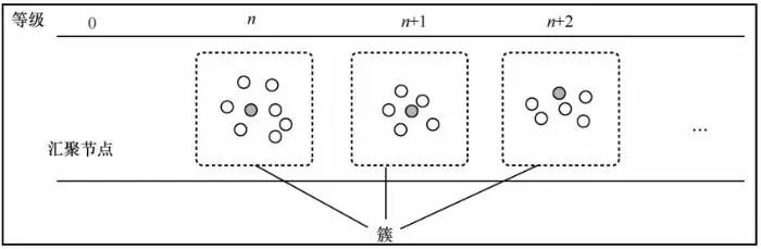
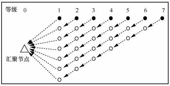
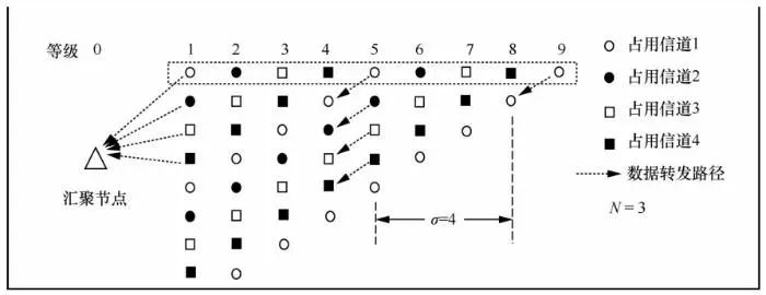
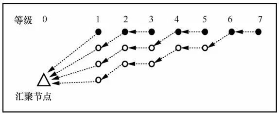
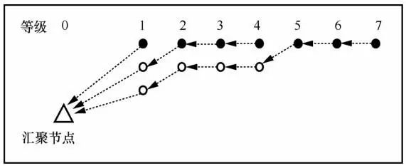
2.1 Network Topology

In LSN, several sensor nodes (equipped with sensors to perceive the environment) and redundant nodes (without sensors, serving only as relay nodes) are deployed, with the sink node located at one end of the network for data collection. Sensor nodes are divided into several clusters based on a clustering algorithm, with one node selected as the cluster head, and the remaining nodes in the cluster sending the data they perceive to the cluster head. There has been considerable research on clustering algorithms, but clustering algorithms are not the focus of this paper.
The classification of node levels in the network is based on the sink node, cluster head, and redundant nodes, with the following principles:
1) The level of the sink node is denoted as 0.
2) Nodes within the effective transmission range of the sink node are assigned a level of 1.
3) Nodes that are one hop away from nodes with level n are assigned a level of n+1.
4) If a node can be classified into multiple levels according to rule 3, it always chooses the smallest level to join.
The LSN topology is illustrated in Figure 1, where each dashed box represents a cluster, black nodes represent sensor nodes, and white nodes represent redundant nodes; the member nodes within the cluster are not displayed.
An Energy-Efficient Multi-Channel MAC Protocol for Linear Sensor Networks
Figure 1 LSN Topology
To utilize redundant nodes to alleviate the energy hole problem, MRPDC allows a cluster head node to forward data received from cluster member nodes to lower-level redundant nodes. Redundant nodes with a level greater than 1 will forward data to lower-level redundant nodes; while redundant nodes with a level of 1 will send data to the sink node. Thus, data transmission in the network, as shown in Figure 1, will follow the logical topology illustrated in Figure 2 (this paper defines the transmission path as the data transmission path from the source node where the data is generated to the sink node, with dotted arrows indicating the data transmission path).
An Energy-Efficient Multi-Channel MAC Protocol for Linear Sensor Networks
Figure 2 Logical Topology of Network Data Transmission

2.2 Pipelined Transmission on the Transmission Path

In MRPDC, nodes periodically sleep to save energy. Specifically, each node has three different states in sequence.
R state: Receiving packets forwarded from other nodes.
T state: Forwarding packets to other nodes.
S state: The node shuts down its receiver and enters sleep mode, not forwarding or receiving packets.
To achieve pipelined transmission and reduce transmission delay, the sleep-wake scheduling between nodes on a data transmission path is staggered. The schematic diagram of pipelined transmission on a vertical data transmission path is shown in Figure 3. Since sending and receiving occur in pairs, the durations of R state and T state are the same, referred to in this paper as a slot. After a node in R state receives data, it can enter T state in the next slot to forward that data, thus forming pipelined transmission along the transmission path. The duration of S state is ξ slots (ξ is a positive integer). The various states of a node occur periodically. If the duration of a slot is denoted by tslot, the duration of S state is ξ.tslot, and the duration of one cycle is tcycle as follows:

An Energy-Efficient Multi-Channel MAC Protocol for Linear Sensor Networks

An Energy-Efficient Multi-Channel MAC Protocol for Linear Sensor Networks

Figure 3 Schematic Diagram of Pipelined Transmission on a Vertical Data Transmission Path
After level classification, the packet transmission mode is as follows: a node with level i+1 enters T state and forwards data to a node with level i (which is in R state), while a node with level i-1 is in S state at that moment; when a node with level i enters T state, it forwards data to a node with level (currently in R state), and a node with level i+1 is in S state at that moment.
Since there may be multiple transmission paths in the network, nodes at the same level will contend for the channel when sending data in T state. Similar to the existing DCPF protocol, MRPDC sets a contention window (CW) and employs an RTS/CTS (request-to-send/clear-to-send) handshake mechanism for data transmission, as illustrated in Figure 4. Therefore, the duration of a slot tslot is as follows:

An Energy-Efficient Multi-Channel MAC Protocol for Linear Sensor Networks

An Energy-Efficient Multi-Channel MAC Protocol for Linear Sensor Networks
Figure 4 Data Transmission Based on Channel Contention and RTS/CTS Handshake Mechanism
Where ncw is the number of unit slots included in a contention window, tcw is the duration of each unit slot, tDIFS is the duration of the Distributed Coordination Function Inter-Frame Space, and tSIFS is the duration of Short Inter-Frame Space. tRTS, tCTS, tDATA, and tACK represent the time required to send and receive an RTS, CTS, DATA (data packet), and ACK (acknowledgment) packet during data transmission. During packet transmission, interference is caused to nodes within approximately two hops, thus ξ≥2. Additionally, the source node experiences waiting delay from data generation to successful transmission due to node sleep. The larger the ξ, the longer the node sleep time. In the worst-case scenario, if a node perceives data just as it enters sleep mode, it must wait for the entire sleep duration before entering active mode to send data. In the best-case scenario, if a node perceives data while in active mode, it can immediately send the data out, resulting in shorter wait time. Overall, the larger the ξ, the longer the average wait time required for this process. However, the proposed scheme, due to its pipelined transmission approach, means that once the perceived data is successfully sent out by the source node, the delay on the link is not affected by the value of ξ.

2.3 Multi-Channel Model

Considering two scenarios regarding the number of available channels in the network: the number of available channels is greater than or equal to the number of transmission paths, and the number of available channels is less than the number of transmission paths. In the case where the number of available channels is greater than or equal to the number of transmission paths, the MRPDC protocol assigns different channels to each transmission path, with no interference between channels. In the case where the number of available channels is less than the number of transmission paths, multiple transmission paths will share one channel, and there will still be transmission competition and interference issues between nodes. To address this, the MRPDC protocol employs staggered time slots to further avoid interference. Specifically, considering that the interference range of nodes during data transmission is twice the transmission range, to ensure that any two adjacent data transmissions (which may be on the same or different paths) do not interfere with each other, they must be separated by at least two levels, meaning that the number of hops between two nodes in transmission state must be at least 4 hops, that is, σ≥4. If the number of transmission paths sharing the same channel is N, then σ and ξ need to satisfy:

An Energy-Efficient Multi-Channel MAC Protocol for Linear Sensor Networks

Multi-channel data transmission based on redundant node deployment is illustrated in Figure 5 (excluding the sink node, the nodes within the dashed box in the figure are sensor nodes, while the rest are redundant nodes). The number of available orthogonal channels is M =4, and the sensor nodes and redundant nodes are classified into H =9 levels, with 7 transmission paths established as described in section 2.1. If σ=4 and ξ=10, the maximum number of transmission paths sharing the same channel is:

An Energy-Efficient Multi-Channel MAC Protocol for Linear Sensor Networks.

An Energy-Efficient Multi-Channel MAC Protocol for Linear Sensor Networks
Figure 5 Multi-Channel Data Transmission Based on Redundant Node Deployment

3 Implementation of MRPDC Protocol

Unless otherwise specified, the term “node” in the following sections refers to both sensor nodes and redundant nodes, while “sensor node” specifically refers to cluster head nodes. The properties maintained by each node are shown in Table 1, and the names of the listed properties will be explained in subsequent sections.

An Energy-Efficient Multi-Channel MAC Protocol for Linear Sensor Networks

3.1 Node Level Classification

In the initial phase, the level attribute of the sink node is set to 0, while all other nodes are set to -1. All nodes operate on a common channel, meaning the Channel attribute value is 0, and the Sinkid attribute is set to -1, and the last_flag attribute is set to False. The sink node constructs message I, with the structure of message I shown in Table 2. In message I, the grade field is set to 0, and the source field is set to the identifier of the sink node. Once message I is constructed, the sink node broadcasts message I.
An Energy-Efficient Multi-Channel MAC Protocol for Linear Sensor Networks

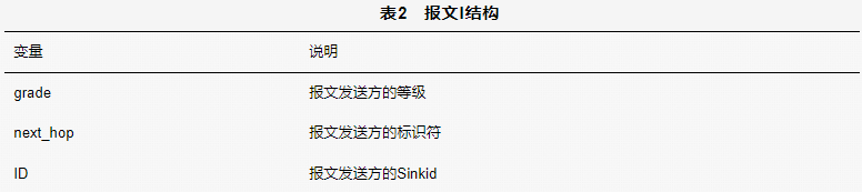
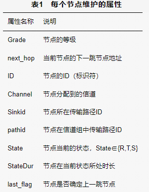
Nodes within one hop of the sink node (denoted as node) will receive message I, and the attributes of the nodes will be updated based on the information in message I as follows:

1) node.Grade=I.grade+1, the node updates its attribute to the value of the grade field in message I plus one.
2) node.next_hop=I.source, the node updates its next_hop attribute to the value in the source field of the message.
If the receiver is a sensor node that has not joined the network, it must also update the information in message I and its own Sinkid field, and then broadcast message I.
1) I.grade=node.Grade, the grade field in message I is updated to the grade of the sensor node.
2) I.sinkid=node.Grade, the sinkid field in message I is updated to the current grade of the sensor node.
3) I.source=node.ID, the source field in message I is updated to the identifier of the current node.
4) node.Sinkid=node.Grade, the sensor node updates its Sinkid attribute to the current grade of the node.
If the receiver is a redundant node that has already joined the network, and its grade equals the previous grade of the broadcasting node (denoted as node A), that is, the node’s grade equals the value in the grade field of message I minus 1, and these redundant nodes have not yet determined the previous hop node (i.e., the value of last_flag is False), they will compete to become the next hop node of node A. These redundant nodes must compete to reply with an RTS message using the contention window upon receiving message I, with the RTS message structure shown in Table 3. Node A will only unicast reply to the first received RTS message (node B) with a CTS message, the structure of the CTS message is shown in Table 4. After receiving the CTS message, node A will regard node B as its only next hop node, and node B will set the last_flag attribute to True, indicating that node A has uniquely determined with node B, while also setting the Sinkid attribute of node B to the value in the sinkid field of the CTS message. After confirming the previous hop, node B will again change the grade field in message I to the value of the current node’s Grade attribute and the source to the identifier of the current node. It continues to broadcast to lower-level nodes, sequentially determining the identifier of the next hop node until the next hop is the sink node.
An Energy-Efficient Multi-Channel MAC Protocol for Linear Sensor Networks

An Energy-Efficient Multi-Channel MAC Protocol for Linear Sensor Networks

Since nodes must broadcast message I from high level to low level to the sink node, sensor nodes that have not joined the network must wait for lower-level nodes to determine the route before continuing to broadcast message I, meaning they must wait for tM ×(Grade-1), where tM =tI+tRTS+tCTS, with tI, tRTS, and tCTS representing the time required to send or receive messages I, RTS, and CTS respectively.
Thus, the leveling process concludes. All nodes are assigned a level, maintain a Sinkid attribute, and determine the network routing table.

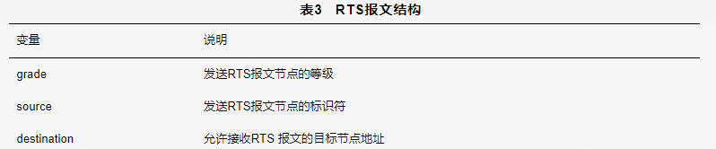
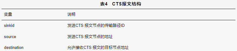
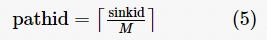
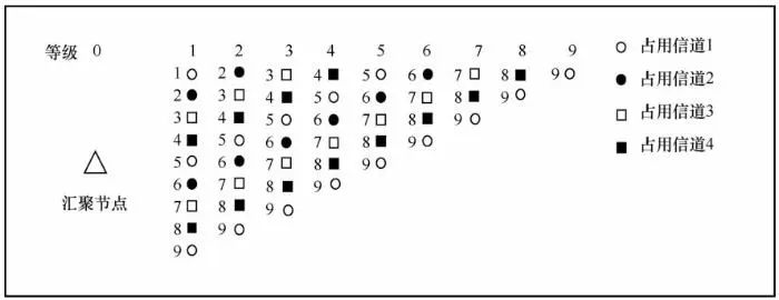
3.2 Channel Allocation

The total number of available orthogonal channels in the network is represented by M. MRPDC divides each transmission path into corresponding channel groups, specifically, transmission paths operating on the same channel are grouped together. For instance, in Figure 5, sensor nodes at levels 1, 3, 7, and 9 are assigned to the first channel group (operating on channel 1), while sensor nodes at levels 2, 4, 6, and 8 are assigned to the second channel group (operating on channel 2). After a node joins the network, the channel assigned to each node is:

An Energy-Efficient Multi-Channel MAC Protocol for Linear Sensor Networks

The transmission path of the node in the current channel group is indexed as follows:

An Energy-Efficient Multi-Channel MAC Protocol for Linear Sensor Networks

Thus, the channel allocation process concludes, and nodes that join the network are assigned a channel and a corresponding path ID (as shown in Table 1) within the same channel group to facilitate time scheduling allocation between different transmission paths. The schematic diagram of channel allocation is shown in Figure 6, where the number of available channels M is 4, and the number of sensor nodes in the network is 9. The numbers to the left of each node indicate the Sinkid maintained by the nodes. During this process, nodes still operate on a common channel.
An Energy-Efficient Multi-Channel MAC Protocol for Linear Sensor Networks
Figure 6 Schematic Diagram of Channel Allocation

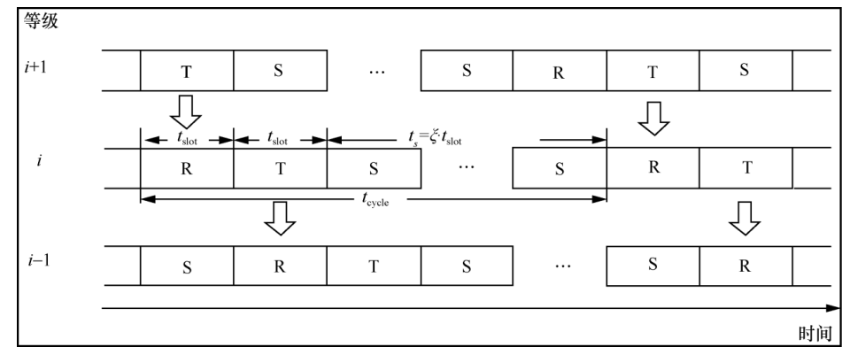
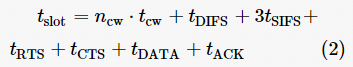
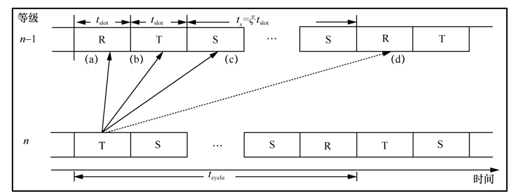
3.3 Establishment of Node Time Schedule

During the establishment of the node time schedule, the sink node needs to construct and broadcast an IM message when entering R state; the structure of the IM message is shown in Table 5.

An Energy-Efficient Multi-Channel MAC Protocol for Linear Sensor Networks

In which the order field starts from 1, and each time an IM message is sent, the order increases by 1, until the last IM message is broadcasted at An Energy-Efficient Multi-Channel MAC Protocol for Linear Sensor Networks. The sink node broadcasts an IM message every σt slot interval, and the algorithm for constructing and broadcasting the IM data packet by the sink node is shown in Algorithm 1.
Algorithm 1: Algorithm for Constructing and Broadcasting IM Data Packet by the Sink Node
Input: Initial IM message, H, M, σ, tslot Output: Updated IM data packet
IM.grade ← 0
IM.state ←R
IM.duration ← 0
for n←1toAn Energy-Efficient Multi-Channel MAC Protocol for Linear Sensor Networksdo
IM.order←n
Send IM out
Wait for σ.t slot
end for
When the sink node sends the IM data packet in R state, there are four situations illustrated in Figure 7: nodes may be in T state; nodes may be in S state; nodes may be in R state; or nodes may enter the next cycle.

An Energy-Efficient Multi-Channel MAC Protocol for Linear Sensor Networks

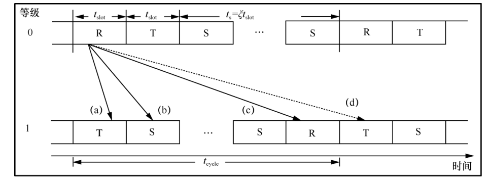
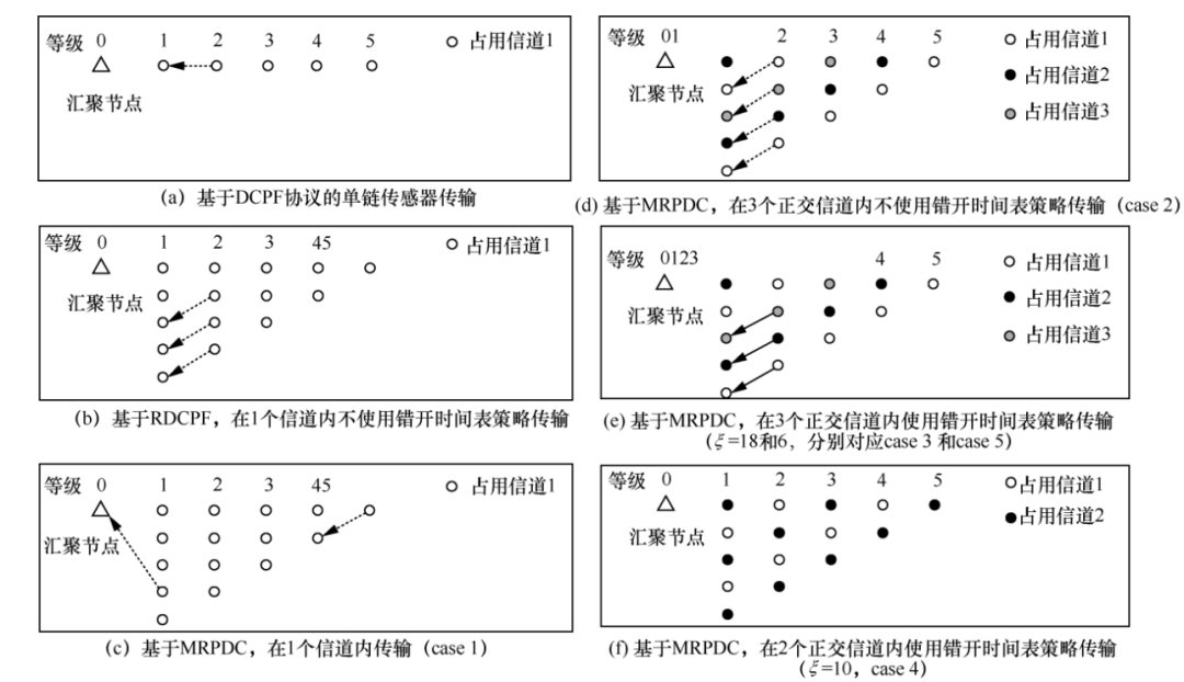
Figure 7 Four Situations When the Sink Node Sends IM Data Packet in R State

After a node receives the IM message, it needs to calculate the propagation delaytdelay. If the propagation delay is sufficiently large, meaning the data packet arrives at the receiving node after the current cycle of the sending node has passed, the number of cycles that this duration spans is denoted as L, calculated as follows:

An Energy-Efficient Multi-Channel MAC Protocol for Linear Sensor Networks

If L≥1, it indicates that the node has entered the next cycle. To facilitate the establishment of the node time schedule, it is necessary to calculate δ, which is calculated as:

An Energy-Efficient Multi-Channel MAC Protocol for Linear Sensor Networks

The IM message propagates from the sink node along the transmission path to the sensor nodes. After receiving the IM message and determining the time schedule, the node updates the IM message and broadcasts it after entering R state. The algorithm for receiving the IM data packet by the node is shown in Algorithm 2. After broadcasting the message, the node needs to switch to the channel assigned during the channel allocation process, while other nodes that receive the IM message broadcasted by lower-level nodes process and broadcast it to the sensor nodes until completion. The IM message is transmitted hop by hop, and thus, all nodes required for data transmission switch to the corresponding channel and establish their time schedules.
Algorithm 2: Algorithm for Receiving IM Data Packet by the Node
Input: Received IM data packet, ζ
Output: Node attributes <State, StateDur>
If IM.order==node.pathid and IM.grade==node.grade-1 then
ifAn Energy-Efficient Multi-Channel MAC Protocol for Linear Sensor Networksthen
State=T
StateDur = δ
else ifAn Energy-Efficient Multi-Channel MAC Protocol for Linear Sensor Networksthen
State = S
An Energy-Efficient Multi-Channel MAC Protocol for Linear Sensor Networks
else
State=R
An Energy-Efficient Multi-Channel MAC Protocol for Linear Sensor Networks
end if
else
dropIM
end if

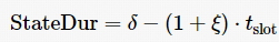
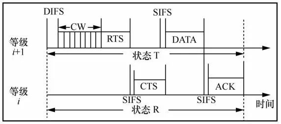
3.4 Data Transmission

During the data transmission phase, the sensor nodes in the network perceive data from the environment. To transmit data, sensor nodes need to find the next hop during the data transmission process and deliver the data packet. If the sensor node’s level is 1, the next hop is the sink node; if the sensor node’s level is not 1, it needs to find a redundant node to deliver the data packet. Similarly, if the redundant node’s level is 1, the next hop during data transmission is the sink node; if the redundant node’s level is not 1, it still needs to find a redundant node to deliver the data packet during data transmission.
As noted in sections 3.2 and 3.3, all nodes assigned the same channel will share the same channel; however, the transmission paths may differ based on the sinkid, and the time schedules corresponding to different sinkids will also interleave. Therefore, even if two data transmissions are assigned to the same channel, they will not interfere with each other due to differing paths. Thus, during data transmission, the sender adds its own level and sinkid to the packet. Nodes with a level not equal to 1 will receive the data packet from lower-level redundant nodes with the same sinkid; while nodes with a level of 1 will directly deliver the data packet to the sink node.

3.5 Solutions for Redundant Node Failure

If a redundant node fails in the network, it will lead to data forwarding failure on that transmission path. Considering that during the leveling process, some redundant nodes that have not joined the routing (last_flag attribute is False) will also be assigned levels, these nodes can serve as backup nodes for the redundant nodes, promptly taking over the role of the corresponding node during failure.
During data transmission, the receiver will reply with an ACK message to confirm successful reception of the data packet. If a node (denoted as X, with level n) does not receive an ACK during data transmission, it can infer that the next hop node has failed. At this point, node X initiates an election, and redundant nodes with a level smaller than X, not yet part of the routing, and without an assigned sinkid will compete to respond. Node X selects one of these redundant nodes (denoted as Y, with level n – 1) as its next hop during data transmission. Node X assigns the same sinkid to Y and sets the correct time schedule for Y. The schematic diagram of the time schedule set by node X for node Y is shown in Figure 8. Since other nodes in the network are already in working state, when node X enters T state, it sends a reIM data packet, setting the time schedule for node Y. The algorithm for setting the time schedule for the redundant node replacing the failed node is shown in Algorithm 3. After establishing the time schedule for node Y, it replies to node X with IMack. Thus, node X can re-forward data to node Y. This approach ensures that when redundant nodes fail, the network can continue to operate with the help of other redundant nodes, enhancing the robustness of the network.

An Energy-Efficient Multi-Channel MAC Protocol for Linear Sensor Networks

Figure 8 Schematic Diagram of Time Schedule Set by Node X for Node Y
Algorithm 3: Algorithm for Setting Time Schedule for Redundant Node Replacing Failed Node
Input: Received IM data packet, ξ, sinkid, M
Output: Y node attributes <State, StateDur>
IfAn Energy-Efficient Multi-Channel MAC Protocol for Linear Sensor Networksthen
State= R
StateDur= δ
else ifAn Energy-Efficient Multi-Channel MAC Protocol for Linear Sensor Networksthen
State= T
An Energy-Efficient Multi-Channel MAC Protocol for Linear Sensor Networks
else
State= S
An Energy-Efficient Multi-Channel MAC Protocol for Linear Sensor Networks
end if

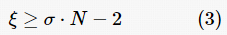
3.6 Number of Redundant Nodes

In the network topology illustrated in Figure 2, each node (excluding the sink node) can send data from at most one source node (including the case where the source node sends its own perceived data). The total number of redundant nodes that need to be deployed is H(H-1)/2, where H represents the number of levels into which the nodes in the network are classified. In this case, the number of redundant nodes can be quite large; for example, when H =7, 21 redundant nodes need to be deployed. To reduce the number of redundant nodes, one can allow each node (excluding the sink node) to send data from at most n source nodes, where a larger n results in a smaller required number of redundant nodes. For example, when H =7, the corresponding network topologies for n=2 and n=3 require only 9 and 5 redundant nodes, respectively, as shown in Figures 9 and 10.
An Energy-Efficient Multi-Channel MAC Protocol for Linear Sensor Networks
Figure 9 Network Topology Corresponding to n=2
An Energy-Efficient Multi-Channel MAC Protocol for Linear Sensor Networks
Figure 10 Network Topology Corresponding to n=3
According to the aforementioned deployment methods, generally, if H %n=0, the required number of redundant nodes isAn Energy-Efficient Multi-Channel MAC Protocol for Linear Sensor Networks; if H %n≠0, letAn Energy-Efficient Multi-Channel MAC Protocol for Linear Sensor Networks, the required number of redundant nodes isAn Energy-Efficient Multi-Channel MAC Protocol for Linear Sensor Networks
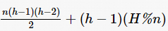
. When n=1, the maximum number of redundant nodes is needed, but the energy consumption among nodes in the network is the most balanced. As n increases, the required number of redundant nodes decreases, but the balance of energy consumption among nodes worsens. Particularly, when n=H, no redundant nodes need to be deployed, but energy consumption balance is the worst, and the energy hole problem is most severe. Therefore, network designers can decide the number of redundant nodes to deploy based on actual conditions.

4 Experimental Design and Analysis

4.1 Experimental Environment and Related Parameters

This paper implements MRPDC based on the OPNET network simulation platform and compares it with existing DCPF and RDCPF protocols to evaluate the performance of the protocol. The experimental parameter settings are shown in Table 6, with the number of sensor nodes in the network being 5 (representing 5 cluster head nodes), ξ=18, σ=4, and the queue length for each node being 15. To adequately compare MRPDC, two optimal scenarios with ξ set to 10 and 6 were added. The seven network scenarios in the simulation are shown in Figure 11, corresponding to the following seven scenarios.
1) Single-hop sensor transmission based on DCPF protocol (as shown in Figure 11(a)).
2) RDCPF-based transmission in one channel without using staggered time scheduling strategy (as shown in Figure 11(b)).
3) MRPDC-based transmission in one channel (case 1, as shown in Figure 11(c)).
4) MRPDC-based transmission in three orthogonal channels without using staggered time scheduling strategy (case 2, as shown in Figure 11(d)).
5) MRPDC-based transmission in three orthogonal channels using staggered time scheduling strategy (case 3, as shown in Figure 11(e)).
6) MRPDC-based transmission with ξ=10 in two orthogonal channels using staggered time scheduling strategy (case 4, as shown in Figure 11(f)).
7) MRPDC-based transmission with ξ=6 in three orthogonal channels using staggered time scheduling strategy (case 5, as shown in Figure 11(e)).
An Energy-Efficient Multi-Channel MAC Protocol for Linear Sensor Networks
Figure 11 Seven Network Scenarios in the Simulation
This paper considers several basic evaluation metrics.
1) Packet delivery ratio: The ratio of the total number of data packets successfully received by the sink node to the total number of packets generated in the network; a higher value indicates a lower packet loss rate in the network.
2) Throughput: The amount of data packets successfully received by the sink node per second.
3) Average energy consumption per packet: The average energy required for the sink node to receive a data packet, indicating the transmission efficiency of the protocol.
4) Packet delivery latency (PDL): The average time taken for each data packet to be transmitted from the source node at the same level to the sink node.
5) Average energy consumption per node at each level: The average energy consumption of nodes at each level.
In the simulation, throughput, packet delivery ratio, average energy consumption of network nodes, average duty cycle of network nodes, and average energy consumption per packet are based on the packet generation rate of λ packets/s (sensor nodes generate data following a Poisson distribution, with pkt being the abbreviation for packet), increasing from 0.05 to 0.5 in increments of 0.05. Based on the throughput results, λ=0.05 and λ=0.1 were taken for statistics on packet delivery latency and average energy consumption per node at each level.

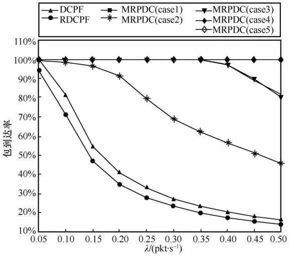
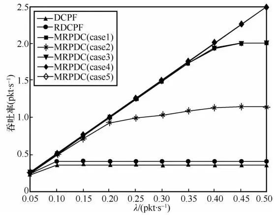
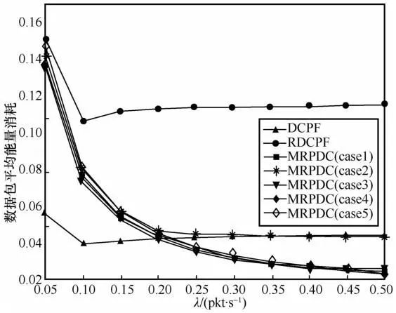
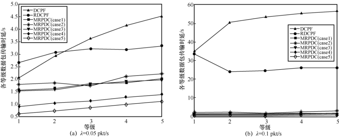
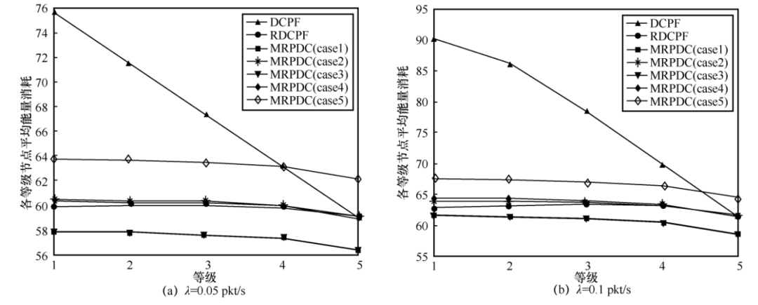
4.2 Experimental Results Analysis

4.2.1 Packet Delivery Ratio
The packet delivery ratio is shown in Figure 12. As can be seen, with the increase in packet generation rate, the results under the RDCPF scenario are the worst, as dispersing packets originally on the same transmission path to redundant nodes on different paths leads to competition for the channel during data transmission from higher to lower levels, resulting in more contention and interference compared to DCPF. MRPDC alleviates the competition for sending data packets among nodes on different transmission paths by integrating multi-channel resource allocation. Secondly, under the same number of sleep slots ξ, the performance of data transmission in MRPDC using staggered strategies achieves optimal results, regardless of whether using a single channel or multiple channels, because this scenario ensures that nodes can achieve interference-free data packet transmission according to the time schedule upon awakening. However, nodes on a single channel must satisfy condition (3) to implement staggered strategies, while the introduction of multi-channels can increase the control range of node sleep slots, adapting to more usage scenarios, and allowing for shorter sleep slots to be set as needed, resulting in a higher packet delivery ratio compared to using a single channel.
An Energy-Efficient Multi-Channel MAC Protocol for Linear Sensor Networks
Figure 12 Packet Delivery Ratio
4.2.2 Throughput
The throughput is shown in Figure 13. It can be seen that under the same number of sleep slots, the method using staggered strategies receives more data packets, while the RDCPF scenario performs worse than DCPF due to increased collisions resulting from more transmission paths. Similarly, the multi-channel scenario achieves higher throughput by using shorter sleep slots.
An Energy-Efficient Multi-Channel MAC Protocol for Linear Sensor Networks
Figure 13 Throughput
4.2.3 Average Energy Consumption per Packet
The average energy consumption per packet is shown in Figure 14. It can be seen that as the packet generation rate increases, the average energy consumption per packet decreases, eventually stabilizing, because as more packets are generated, the entire network ensures that nodes can have packets after awakening, leading to higher efficiency. In the MRPDC scenario using staggered strategies, the average energy consumption per packet is lower, and combined with the packet delivery ratio, it can be observed that after reaching a certain height for packet delivery ratio, it can still maintain lower average energy consumption, indicating higher energy usage efficiency.
An Energy-Efficient Multi-Channel MAC Protocol for Linear Sensor Networks
Figure 14 Average Energy Consumption per Packet
4.2.4 Packet Transmission Delay
The packet transmission delay for each level is shown in Figure 15. It can be observed that when the packet generation rate is 0.05 pkt/s, as the level increases, the time taken for packets to be transmitted from generation to reception becomes longer, because as the node level increases, the number of hops that packets need to traverse and the waiting time in the queue also increase. The delay in the DCPF scenario is higher, and the difference increases with the level; however, when using staggered strategies, the delay for nodes is lower compared to DCPF, and the delay differences between levels are also smaller. Additionally, the delay in multi-channel scenarios with shorter sleep slots is also lower, yielding better results. Moreover, it can be seen in case 2 that the delay for level 3 is lower, as the transmission paths for sensor nodes at levels 1 and 4 (and 2 and 5) are on the same channel, leading to more contention and increased delays, while level 3’s sensor node operates on a separate channel, resulting in lower average delays. When the packet generation rate is 0.1 pkt/s, it can also be seen that the delay is lower when using MRPDC with staggered strategies.

An Energy-Efficient Multi-Channel MAC Protocol for Linear Sensor Networks

Figure 15 Packet Transmission Delay for Each Level
4.2.5 Average Energy Consumption per Node at Each Level
The average energy consumption per node at each level is shown in Figure 16. It can be seen that regardless of whether the packet generation rate is 0.05 pkt/s or 0.1 pkt/s, in the DCPF scenario, as the level decreases, the average energy consumption increases, because nodes closer to the sink must forward more packets, leading to higher energy consumption. However, after deploying redundant nodes, sensor nodes do not need to relay data; each sensor node has its own independent transmission path, sharing the energy consumption burden with redundant nodes, resulting in less variation in average energy consumption even among nodes of different levels. Furthermore, compared to the energy consumption in the DCPF scenario, the overall energy consumption in the network remains at a lower range after deploying redundant nodes.
An Energy-Efficient Multi-Channel MAC Protocol for Linear Sensor Networks
Figure 16 Average Energy Consumption per Node at Each Level

5 Conclusion

This paper proposes a multi-channel MAC protocol for linear sensor networks based on redundant node deployment and duty-cycled scheduling—MRPDC. This protocol avoids excessive participation of sensing nodes in data forwarding at the cost of deploying redundant nodes, effectively alleviating the energy hole problem, and utilizes orthogonal channels and pipelined scheduling to avoid competition and interference during data transmission. The redundant nodes in the proposed protocol are used solely as relay nodes for data forwarding, thus do not require sensor devices, making them relatively inexpensive. Additionally, this paper proposes corresponding solutions for the failure of redundant nodes, enhancing the robustness of the proposed protocol. Simulation results based on the OPNET network simulation software indicate that the proposed protocol outperforms existing protocols in terms of energy efficiency, packet arrival rate, throughput, and packet transmission delay.

Author Information

Tong Fei (1987-), male, PhD, Associate Professor at Southeast University, Master Supervisor, main research directions include Internet of Things security, ubiquitous network intelligence and security, etc.
Sui Rucong (1996-), male, Master’s student at Southeast University, main research directions include wireless communication networks, wireless ad hoc networks, etc.
Chen Yu (1999-), male, Master’s student at Southeast University, main research directions include human-computer interaction and security, etc.
Su Heng (2000-), male, Master’s student at Southeast University, main research directions include network security based on big data and deep learning.
Liu Hengrui (2000-), male, student at Southeast University, main research directions include blockchain application security, Internet of Things security, etc.
Su Shangfeng (2001-), male, student at Southeast University, main research directions include Internet of Things security, wireless sensor networks, etc.
Yan Yuke (2000-), female, Master’s student at Southeast University, main research directions include artificial intelligence, deep learning, etc.
An Energy-Efficient Multi-Channel MAC Protocol for Linear Sensor Networks

Link to Previous Issue

Contents & Abstracts of IoT Journal 2022 Issue 4

Contact Us:

Tel:010-81055691

E-mail:[email protected]

Journal Introduction
The Internet of Things Journal is a Chinese academic journal sponsored by the Ministry of Industry and Information Technology and published by the People’s Posts and Telecommunications Press. The purpose of the journal is to serve scientific development, disseminate scientific knowledge, promote technological innovation, and cultivate scientific and technological talent.

Scopus Indexed

Recommended Chinese Technology Journal by the China Communications Society (T1)

Recommended Chinese Technology Journal by the China Computer Society (T2)

Ulrichsweb Indexed

Journal Homepage

http://www.infocomm-journal.com/wlw/CN/2096-3750/home.shtml

Online Submission

http://cbpt.infocomm-journal.com/Journalx_wlw/authorLogOn.action

An Energy-Efficient Multi-Channel MAC Protocol for Linear Sensor Networks

An Energy-Efficient Multi-Channel MAC Protocol for Linear Sensor Networks

Long press or scan the QR code to follow us, all articles can be read online for free

Leave a Comment