Photoelectric sensors utilize various properties of light to detect the presence of objects or changes in their surface conditions.
Photoelectric sensors mainly consist of a light-emitting part that transmits light and a light-receiving part that receives light. When the projected light is obscured by the detected object or reflected back, the amount of light reaching the receiving part changes. As long as the receiving part detects any change, it converts it into an electronic signal and outputs it. The light commonly used is mainly visible light (primarily red and green, with red used for color discrimination) and infrared light.
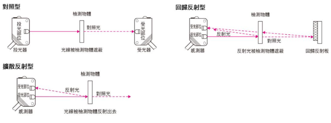
As shown in the figure below, photoelectric sensors can be divided into three main categories.
Features
• Long detection distance
Taking the contrasting type as an example, its detection distance can reach over 10m, far exceeding that of other detection methods (magnetic, ultrasonic, etc.).
• Fewer restrictions on detected objects
Unlike proximity sensors, which can only detect metallic objects, this sensor’s detection principle is based on light obstruction through the detected object, allowing it to detect most objects, including glass, wood, and liquids.
• Short response time
Light itself travels at an extremely high speed; aside from the machine action time required for the electronic components of the sensor circuit, the response time is very short.
• Higher resolution
Through advanced design techniques, the projected light beam can be reduced to a smaller light spot. Additionally, due to the special optical system structure of this product, it can achieve high-resolution targets. This allows for the detection of even small objects or high-precision position detection.
• Non-contact detection
The machine itself does not need to contact the object to perform detection, which means that neither the detected object nor the sensor will be damaged, allowing for long-term use of the sensor.
• Color discrimination
The light reflectivity and absorption rate of the detected object vary based on the wavelength of the projected light and the color combination of the detected object. Photoelectric sensors utilize this property to detect the color of objects.
• Easier adjustments
One type of photoelectric sensor uses visible light projection, making the light beam easily visible, thus simplifying the positioning of the detected object.
Principle
1. Properties of Light
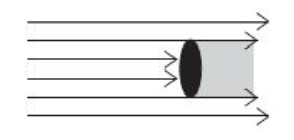
• Straight-line propagation
When light enters air or water, it often travels in a straight line.
The contrasting type sensor uses a slit plate to detect small objects, applying this principle of light.
• Refraction
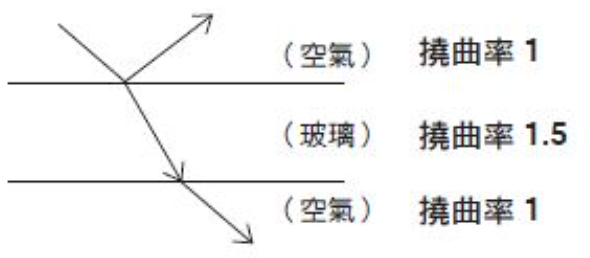
When light enters another medium with a different refractive index, its direction of travel changes.
• Reflection (specular reflection, retroreflection, diffuse reflection)
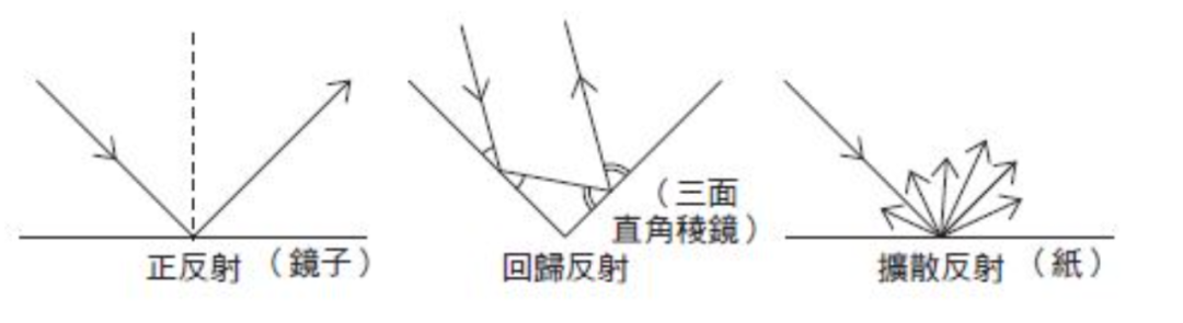
When light hits a flat surface like a mirror or glass, the angle of reflection will equal the angle of incidence, which is known as “specular reflection.”
The shape formed by three mutually perpendicular planes is called a “triangular prism.”
When light is projected onto a triangular prism, it undergoes repeated specular reflection, with the final reflected light traveling in the opposite direction to the projected light. This reflection method is called “retroreflection.”
In principle, most retroreflective plates are correctly arranged from triangular prisms with edges measuring a few millimeters.
Additionally, surfaces like white paper that lack gloss reflect light in all directions, which is known as “diffuse reflection.” The detection method for diffuse reflection products utilizes this principle.
• Polarization
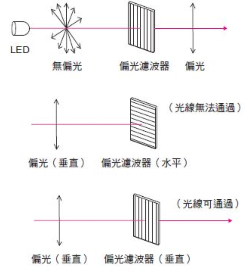
The vibration direction of light waves is perpendicular to the direction of travel. Photoelectric sensors primarily use LEDs as light sources. The light emitted by LEDs vibrates in various directions perpendicular to the direction of travel, a reflection method termed “unpolarized.” An optical filter that restricts the vibration direction of unpolarized light to a single direction is called a “polarizing filter.” In other words, when LED light is projected, the light passing through the polarizing filter vibrates in a single direction, referred to as “polarized” (more accurately termed “linearly polarized”). This allows polarized light vibrating in a particular direction (e.g., vertical) to pass through a polarizing filter that only allows horizontal vibrations.
2. Light Source
• Lighting Methods
〈Pulsed Modulation Lighting〉
Most photoelectric sensors use pulsed modulation lighting, a principle that repeatedly projects light at fixed intervals.
This method is less affected by external interference light, making it suitable for long-distance detection. Models with built-in interference prevention features have their light projection cycles adjusted within a fixed range due to interference light or external factors.
〈DC Lighting〉
This method continuously projects a fixed amount of light, used in marking sensors. Although DC lighting has high-speed responsiveness, its detection distance is shorter and is more susceptible to external interference light.
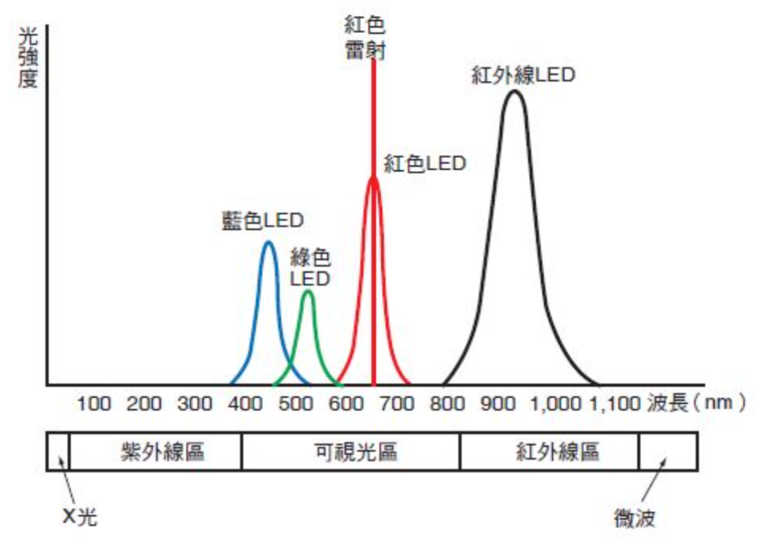
• Light Source Color and Type
3. Triangulation
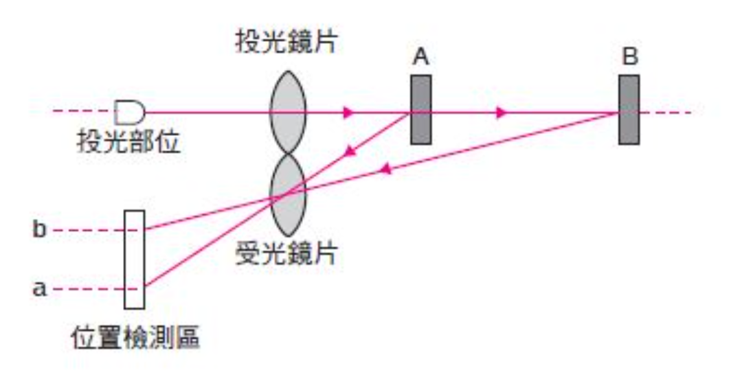
The detection principle used by distance-setting photoelectric sensors is primarily triangulation. The diagram below illustrates the principle of triangulation.
The light emitted by the light-emitting element is diffused and reflected onto the detected object. The reflected light passes through the light-receiving lens and forms an image on the position detection element (the semiconductor element outputs a signal based on the position where the light contacts the detection element). When the detected object is placed close to the optical system at position A, the reflected light images at position a on the position detection element. Conversely, if placed further away at position B, the reflected light images at position b. Therefore, by measuring the imaging position on the position detection element, the distance to the detected object can be calculated.
Classification
1. Classified by Detection Method
(1) Contrasting Type
Detection Method
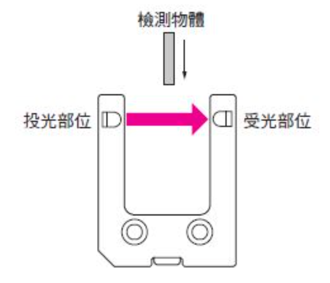
The light emitter should be set opposite the light receiver to allow the light from the emitter to enter the receiver.
When the detected object is placed between the emitter and receiver and the light is obscured, the amount of light entering the receiver decreases.
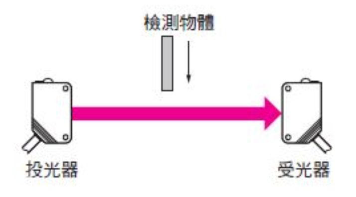
Additionally, the detection method is the same as the contrasting type; in terms of sensor shape, the light-emitting part is integrated, referred to as “groove type.”
Features
(2) Diffuse Reflection Type
Detection Method
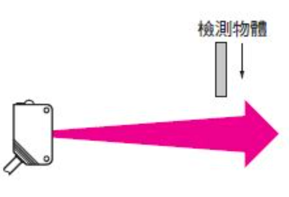
The emitter and receiver are integrated, and the light does not return to the usual receiving part. When the light projected from the emitter hits the detected object, the light reflected from the detected object enters the receiving part, increasing the amount of light received.
Features
(3) Retroreflection Type
Detection Method
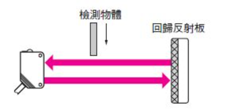
This method adopts an integrated emitter and receiver. The light projected from the emitter is usually reflected onto a reflector placed opposite and then returns to the receiving part. When the light from the detected object is obscured, the amount of light entering the receiving part decreases.
Features
• There is a blind area at close range
(4) Distance-Setting Type
Detection Method
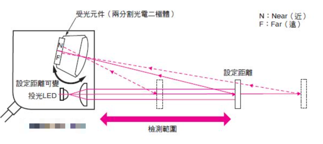
The light-receiving element of the sensor uses a divided photodiode or position detection element. The light beam reflected from the detected object images on the light-receiving element, with the imaging position changing based on the distance to the detected object, utilizing the “triangulation” principle for detection.
The diagram below shows the detection method using a divided photodiode. One end of the divided photodiode (near the housing end) is called the N (Near) side, while the other end is called the F (Far) side. When a detected object exists within the set distance, the reflected light images at the midpoint between the N side and F side, with equal light amounts received by both photodiodes. When the detected object is closer to the sensor than the set distance, the reflected light images on the N side. Conversely, if the detected object is further than the set distance, the reflected light images on the F side. Thus, by calculating the difference in light amounts received by the N side and F side, the position of the detected object can be determined.
Features of Distance-Setting Type
• Less affected by the color of background objects
BGS (Background Suppression) and FGS (Foreground Suppression)
The BGS function refers to not detecting background objects larger than the set distance (e.g., conveyor belts).
The FGS function refers to not detecting small objects close to the set distance and objects returning to the light receiver with light amounts below a specified value, meaning it only detects conveyor belts. Objects with less light returning to the light receiver.
Generally divided into the following three categories:
1. Objects with extremely low reflectivity, i.e., objects darker than black paper
2. Mirror-like objects that reflect almost all light back to the light-emitting side
3. Objects with high reflectivity that scatter light in any direction, such as uneven glossy surfaces. In case C, when the detected object moves, there may temporarily be reflected light returning to the light receiver, necessitating the use of an OFF delay timer to avoid chattering.
Characteristics of BGS Mode and FGS Mode
(5) Limited Reflection Type
Detection Method
Similar to the diffuse reflection type, it uses the reflected light from the detected object for detection. With an optical system that limits the projected light beam and receiving area, the sensor can only detect objects that maintain a fixed distance from the sensor (the overlapping range of the projected light beam and receiving area). As shown in the right diagram, position A cannot detect the object, while position B can.
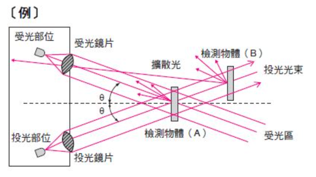
Features
• Less affected by the gloss and tilt of the detected object
2. Classified by Structure
Photoelectric sensors typically consist of a light-emitting part, a light-receiving part, an amplification part, a control part, and a power supply part. Based on their construction, they can be classified into the following categories:
(1) Amplifier-Separated Type
Only the light-emitting part and light-receiving part are separated, with the emitter and receiver (contrasting type) structured separately or made into an integrated emitter-receiver (reflective type). Other amplification and control parts are made into an integrated amplifier unit.
Features
• Signal lines between the emitter, receiver, and amplifier unit are easily affected by interference
(2) Built-in Amplifier Type
Except for the power supply part, this type is integrated (the contrasting type includes the light-emitting part in the emitter and the light-receiving, amplification, and control parts in the receiver). The power supply part is separately made into a power module.
Features
• The light-receiving, amplification, and control parts are integrated, allowing signal lines responsible for receiving small signals to avoid interference
• Generally, while larger than the amplifier-separated type, the non-sensitivity-adjustable type is compact and comparable to the former
(3) Built-in Power Supply Type
This type is fully integrated from the emitter, receiver to the power supply part.
Features
• The emitter and receiver contain built-in power transformers, making this type larger than others
(4) Area Sensor
The light-emitting and light-receiving parts are multi-axial (contrasting type), allowing the selection of the sensor’s detection range based on application.
Features
• Suitable for component picking
Application Fields
Photoelectric sensors are among the most produced and widely applied sensors, used in various fields such as military, aerospace, communication, smart homes, smart transportation, security, LED lighting, toys, detection, and industrial automation control.
Photoelectric Sensor Dust and Turbidity Monitoring
Preventing industrial dust pollution is one of the important tasks in environmental protection. To eliminate industrial dust pollution, it is essential to know the amount of dust emitted, thus monitoring the dust source is necessary, with automatic display and exceeding standard alarms. The turbidity of the dust in the flue is detected by measuring the changes in light transmission through the flue. If the turbidity increases, the light emitted by the source is absorbed and refracted by dust particles, resulting in a decrease in light reaching the detector, thus the strength of the signal output from the light detector reflects changes in flue turbidity.
Smoke alarms also use photoelectric sensors as core components to measure smoke concentration, consisting of an infrared LED and a phototransistor, but the two are not on the same plane (at a certain angle). In a smoke-free state, the phototransistor receives no infrared light; when smoke enters the sensing chamber, smoke particles scatter some of the light beams onto the phototransistor. As the smoke concentration increases, more light beams are scattered onto the sensor, and when the amount of light reaching the sensor exceeds a certain level, the buzzer will emit an alarm signal.
Photoelectric Sensors in Barcode Scanners
When the scanner head moves over a barcode, if it encounters black lines, the light from the LED will be absorbed by the black lines, causing the phototransistor to receive no reflected light, resulting in a high impedance and cutoff state. When it encounters white spaces, the light emitted by the LED is reflected to the base of the phototransistor, generating photocurrent and turning it on. After scanning the entire barcode, the phototransistor transforms the barcode into a series of electrical pulse signals, which are amplified and shaped to form a pulse train, processed by a computer to complete the recognition of the barcode information.
Photoelectric Sensors in Bill Counters
One essential component in a bill counter is the photoelectric sensor. The counter uses non-contact infrared photoelectric detection technology, characterized by simple structure, high accuracy, and fast response.
The bill counter employs two sets of infrared photoelectric sensors. Each sensor consists of an infrared LED and a phototransistor receiving infrared light, with an appropriate distance between them.
When no bills pass through, the receiving tube is illuminated and conducts, outputting 0. When a bill passes through, it blocks the infrared light, causing insufficient light flux to the receiving tube, outputting 1. After the bill passes, the receiving tube again receives infrared light and conducts. This generates a pulse signal at the output of this circuit section, which is shaped and amplified by subsequent circuits and input to a microcontroller, which drives the execution motor and performs counting and display. The reason for using two sets of photoelectric sensors in the bill counter is to detect the integrity of banknotes, preventing damaged bills from being counted.
By detecting the counting of banknotes through photoelectric sensors, the total number of banknotes can be accumulated, and the total count can be displayed visually to the user via an LCD and external display, with automatic alarms for any anomalies.
Photoelectric Sensors in Automatic Meter Reading Systems
With the development of microelectronics, sensor technology, computer technology, and modern communication technology, photoelectric sensors can be used to develop automatic meter reading systems. The aluminum disk of the electric meter rotates under the action of eddy currents and magnetic fields. Using photoelectric sensors can convert the number of rotations of the aluminum disk into pulse counts.
For example, a section of the rotating aluminum disk is painted black, and paired with reflective photoelectric emitter-receiver pairs, when the aluminum disk rotates, pulses are generated at the black-painted section, converting the number of rotations into corresponding pulse counts. These pulses are then sent to the CPU’s T0 port for counting. Using photoelectric isolators can effectively prevent interference signals from entering the microcomputer. Combined with other transmission methods, an automatic meter reading system can be formed.
Photoelectric Sensors in Automated Production Lines
Photoelectric detection methods are widely applied in light industry automation machines due to their high precision, rapid response, and non-contact advantages.
Photoelectric Sensors in Laser Weapons
Due to their high sensitivity to infrared radiation or visible light, photoelectric sensors are more likely to become targets of laser attacks. Moreover, the electronic systems and sensors are easily disturbed by thermal noise and electromagnetic noise generated by lasers, leading to malfunction. On the battlefield, laser weapons attack photoelectric sensors in several ways: using appropriately powered laser beams to “blind” the sensors, preventing them from detecting or continuing to track already detected targets. If the sensors guide weapons toward targets, blinding them will cause them to lose the target. In summary, as sensors play increasingly important roles on the battlefield and are easily subjected to laser attacks, they have become prime targets for low-energy laser weapons.
Photoelectric Sensors in Automotive Applications
On-vehicle entertainment/navigation/DVD system backlight control to ensure ideal backlight brightness under all ambient light conditions; backlight control for rear-seat entertainment displays; instrument panel backlight control (speedometer/rpm gauge); automatic rearview mirror brightness control (typically requires two sensors, one forward and one rearward); automatic headlight and rain sensing control (customized based on requirements); rearview camera control (customized based on requirements).
Providing more comfortable display quality has become one of the most effective solutions, possessing characteristics similar to human vision, which is crucial for automotive applications as these require complete backlighting under all ambient light conditions.
For instance, during the day, users need maximum brightness for optimal visibility, but this brightness can be too bright for nighttime conditions. Therefore, light sensors with good spectral response (good IR attenuation), appropriate dynamic range, and overall good output signal adjustment can easily automate these applications. End-users can set multiple threshold levels (e.g., low, medium, bright) or dynamically adjust the sensor’s backlight brightness.
This also applies to automotive rearview mirror brightness control, where intelligent brightness management is needed when the mirror darkens and/or brightens, achievable through ambient light sensors.
Photoelectric Sensors in Consumer Electronics
Recent advances in semiconductor-like sensors and packaging development have provided end-users with a broader selection of light sensors. Small packaging, low power consumption, high integration, and ease of use are reasons designers increasingly adopt light sensors, expanding their applications in consumer electronics.
For portable applications, if users do not change system settings (usually brightness control), a display always consumes the same amount of energy. In especially bright areas outdoors, users tend to increase the display brightness, which increases system power consumption. However, when conditions change, such as entering a building, most users do not change settings, leading to consistently high system power consumption. By using a light sensor, the system can automatically detect changes in conditions and adjust settings to ensure the display remains at optimal brightness, thus reducing overall power consumption.
In general consumer applications, this can also extend battery life. For mobile phones, laptops, tablets, and digital cameras, feedback from ambient light sensors can automatically control brightness, thereby extending battery life.
Photoelectric sensors utilize light’s variables and have extremely broad applications, such as in escalators, automatic doors, security alarms, automatic lighting, level control, etc. In the future, with the development and popularization of IoT technology, the application of photoelectric sensors will permeate all aspects of human life.
Note: The article is整理转载于网络,仅供参考学习,版权归原作者所有,如涉及侵权,请联系小编删除。