Follow Arm Technology Classroom by clicking the card below
This article is authorized to be transferred from the WeChat public account Embedded Column. This article mainly shares the implementation of simple Asymmetric Multi-Processing (AMP) core-to-core communication using FreeRTOS message buffers, taking the STM32H7 (M4 and M7) dual-core processor as an example.
1. Overview
The communication between STM32H7 dual cores is a solution provided by FreeRTOS, based on FreeRTOS message buffers. This message buffer is a lock-free circular buffer that can transmit data packets of different sizes from a single sender to a single receiver.
Note that this message buffer only provides data transmission and does not provide protocol handling related to communication.
2. Basic Principles
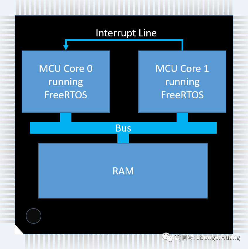
The basic principle of achieving communication between dual cores: the sending and receiving tasks are located on different cores of a multi-core microcontroller (MCU) in an Asymmetric Multi-Processing (AMP) configuration, which means that each core runs its own FreeRTOS program.
At the same time, one core has the ability to generate interrupts in the other core, and both cores have access to a memory area (shared memory). The message buffer is placed in shared memory at an address known to the application running on each core, as shown in the figure below:

Figure 1
Ideally, there will also be a Memory Protection Unit (MPU) to ensure that the message buffer can only be accessed through the core’s message buffer API, and it is best to mark the shared memory as not being occupied by other programs.
3. Single Message Code Description
The official code provided here implements the basic solution (for reference only).
Code to send data to the stream buffer:
xMessageBufferSend(){    /* If a time out is specified and there isn't enough    space in the message buffer to send the data, then    enter the blocked state to wait for more space. */    if( time out != 0 )    {        while( there is insufficient space in the buffer &&               not timed out waiting )        {            Enter the blocked state to wait for space in the buffer        }    }
    if( there is enough space in the buffer )    {        write data to buffer        sbSEND_COMPLETED()    }}
Code to read data from the stream buffer:
xMessageBufferReceive(){    /* If a time out is specified and the buffer doesn't    contain any data that can be read, then enter the    blocked state to wait for the buffer to contain data. */    if( time out != 0 )    {        while( there is no data in the buffer &&               not timed out waiting )        {            Enter the blocked state to wait for data        }    }
    if( there is data in the buffer )    {        read data from buffer        sbRECEIVE_COMPLETED()    }}
If the task enters a blocked state in xMessageBufferReceive() waiting for the buffer to contain data, sending data to the buffer must unblock that task so that it can complete its operation.
When xMessageBufferSend() calls sbSEND_COMPLETED(), the task will not be blocked.

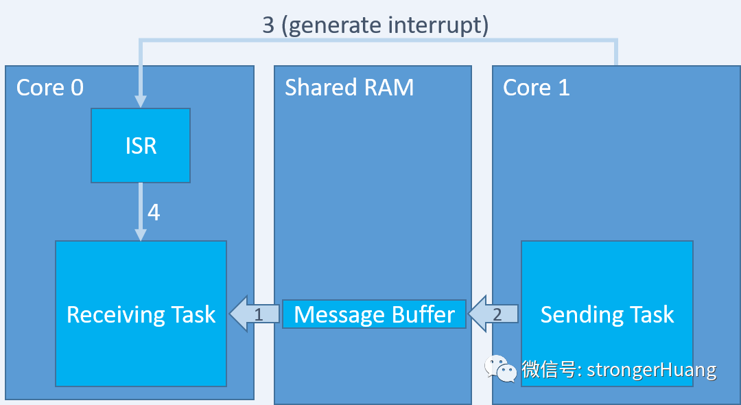
Figure 2
The ISR unblocks the task by passing the handle of the message buffer to the function xMessageBufferSendCompletedFromISR().
As indicated by the arrows in the figure, where the sending and receiving tasks are located on different MCU cores:
1. The receiving task attempts to read data from an empty message buffer and enters a blocked state waiting for data to arrive.
2. The sending task writes data to the message buffer.
3. sbSEND_COMPLETED() triggers an interrupt in the core where the receiving task is executing.
4. The interrupt service routine calls xMessageBufferSendCompletedFromISR() to unblock the receiving task, which can now read from the buffer because it is no longer empty.
4. Multiple Message Code Description
When there is only one message buffer, it is easy to pass the handle of the message buffer to xMessageBufferSendCompletedFromISR().
However, to consider the case of having two or more message buffers, the ISR must first determine which message buffer contains data. If the number of message buffers is small, there are several ways to implement:
● If hardware allows, each message buffer can use a different interrupt line, maintaining a one-to-one mapping between the interrupt service routine and the message buffer.
● The interrupt service routine can simply query each message buffer to see if it contains data.
● A single message buffer can be used to pass metadata (what the message is, what the expected recipient of the message is, etc.) along with the actual data instead of multiple message buffers.
However, if there are a large number of message buffers or if the number is unknown, these techniques are inefficient.
In this case, a scalable solution is to introduce a separate control message buffer. As shown in the code below, sbSEND_COMPLETED() uses the control message buffer to pass the handle of the message buffer that contains data to the interrupt service routine.
Implementation of sbSEND_COMPLETED():
/* Added to FreeRTOSConfig.h to override the default implementation. */#define sbSEND_COMPLETED( pxStreamBuffer ) vGenerateCoreToCoreInterrupt( pxStreamBuffer )
/* Implemented in a C file. */void vGenerateCoreToCoreInterrupt( MessageBufferHandle_t xUpdatedBuffer ){size_t BytesWritten.
    /* Called by the implementation of sbSEND_COMPLETED() in FreeRTOSConfig.h.    If this function was called because data was written to any message buffer    other than the control message buffer then write the handle of the message    buffer that contains data to the control message buffer, then raise an    interrupt in the other core.  If this function was called because data was    written to the control message buffer then do nothing. */    if( xUpdatedBuffer != xControlMessageBuffer )    {        BytesWritten = xMessageBufferSend(  xControlMessageBuffer,                                            &xUpdatedBuffer,                                            sizeof( xUpdatedBuffer ),                                            0 );
        /* If the bytes could not be written then the control message buffer        is too small! */        configASSERT( BytesWritten == sizeof( xUpdatedBuffer );
        /* Generate interrupt in the other core (pseudocode). */        GenerateInterrupt();    }}
Then, the ISR reads the control message buffer to get the handle and passes it as a parameter to xMessageBufferSendCompletedFromISR():
void InterruptServiceRoutine( void ){MessageBufferHandle_t xUpdatedMessageBuffer;BaseType_t xHigherPriorityTaskWoken = pdFALSE;
    /* Receive the handle of the message buffer that contains data from the    control message buffer.  Ensure to drain the buffer before returning. */    while( xMessageBufferReceiveFromISR( xControlMessageBuffer,                                         &xUpdatedMessageBuffer,                                         sizeof( xUpdatedMessageBuffer ),                                         &xHigherPriorityTaskWoken )                                           == sizeof( xUpdatedMessageBuffer ) )    {        /* Call the API function that sends a notification to any task that is        blocked on the xUpdatedMessageBuffer message buffer waiting for data to        arrive. */        xMessageBufferSendCompletedFromISR( xUpdatedMessageBuffer,                                            &xHigherPriorityTaskWoken );    }
    /* Normal FreeRTOS "yield from interrupt" semantics, where    xHigherPriorityTaskWoken is initialised to pdFALSE and will then get set to    pdTRUE if the interrupt unblocks a task that has a priority above that of    the currently executing task. */    portYIELD_FROM_ISR( xHigherPriorityTaskWoken );}

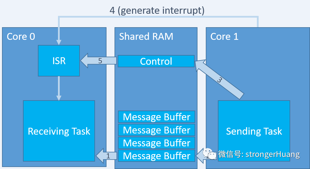
Figure 3
As shown in the figure, the sequence when using the control message buffer is:
1. The receiving task attempts to read data from an empty message buffer and enters a blocked state waiting for data to arrive.
2. The sending task writes data to the message buffer.
3. sbSEND_COMPLETED() sends the handle of the message buffer that now contains data to the control message buffer.
4. sbSEND_COMPLETED() triggers an interrupt in the core where the receiving task is executing.
5. The interrupt service routine reads the handle of the message buffer containing data from the control message buffer and passes that handle to the xMessageBufferSendCompletedFromISR() API function to unblock the receiving task, which can now read from the buffer as it is no longer empty.
Of course, the above only provides the basic principles and methods. The specific implementation should be combined with the actual situation of the project. For more related content, please refer to the official related materials.
Recommended Reading
-
Guide to Porting FreeModbus RTU Embedded Free Software Protocol Stack
-
A Small and Clever Custom Embedded Software Communication Protocol
-
Essential Drawing Tools for Embedded Development


Long press to identify the QR code to add Miss Jishu’s WeChat (aijishu20) and join the Arm Technology Classroom reader group.
Follow Arm Technology Classroom
 Click on “Read the original text” below to read more articles about the Embedded Inn Column.