What is a multimeter?

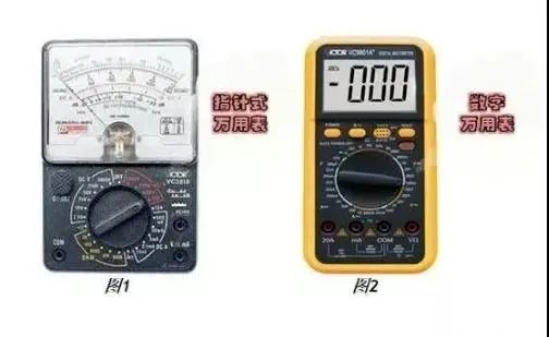
A multimeter, also known as a multi-tester, volt/ohm meter, is a versatile measuring instrument that can be classified into analog and digital types.
It is a multifunctional, multi-range measuring device that can generally measure DC current, DC voltage, AC current, AC voltage, resistance, and audio levels. Some models can also measure AC current, capacitance, inductance, and certain parameters of semiconductors.
How to read the operation panel?
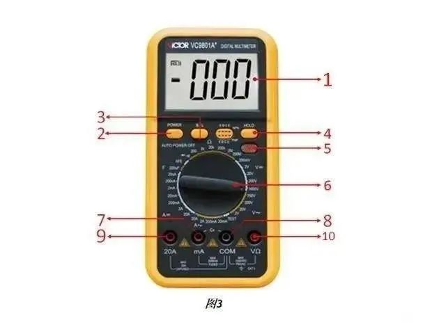
1. LCD Display (shows the measured values)
2. POWER switch: Turns the power on and off.
3. B/L backlight switch: Turns on the backlight, which automatically turns off after about 10 seconds.
4. HOLD switch: Pressing this function key holds the current measured value on the LCD display and shows the “HOLD” symbol. Pressing it again will remove the “HOLD” symbol and exit the hold function.
5. Live wire identification indicator.
6. Rotary switch: Used for selecting the function and range of the meter.
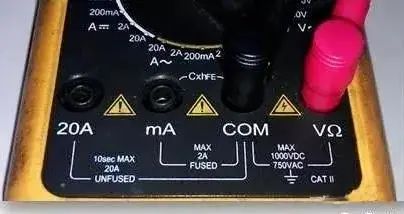
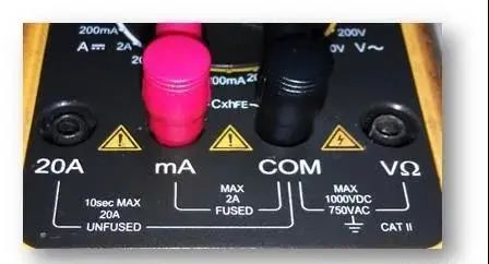
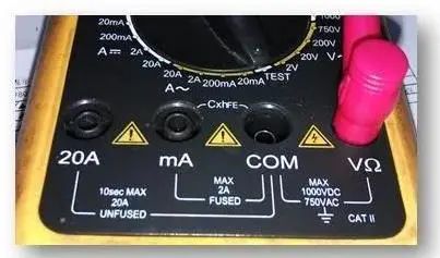
7. Current test socket for less than 2A.
8. Common ground: Positive socket for testing accessories.
9. Current test socket for 20A.
10. Voltage, resistance, and frequency socket.
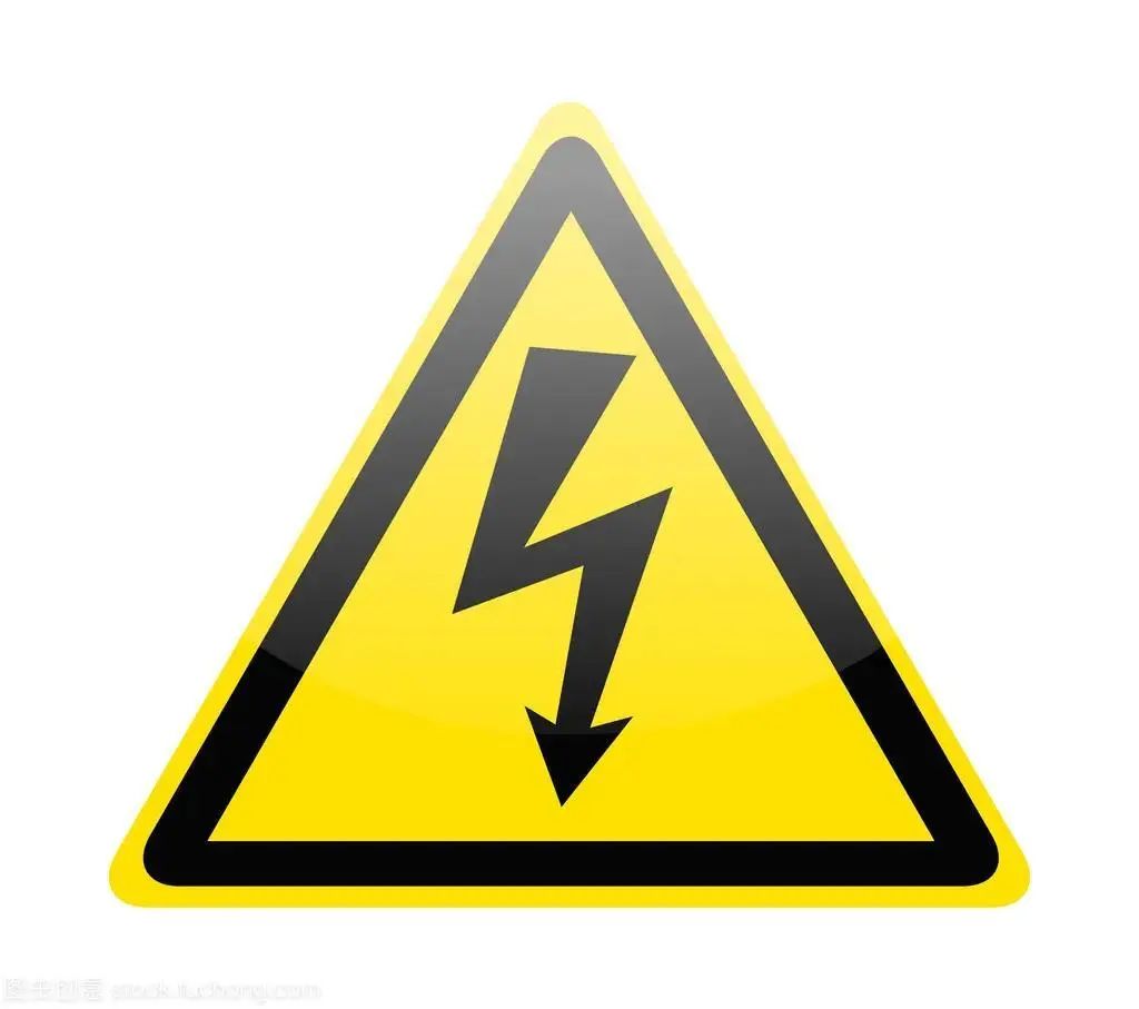
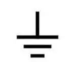
Safety symbol explanations:
(1) Danger of high voltage
(2) Operators must refer to the manual
(3) Grounding
Main functions of the multimeter:
DC Voltage Measurement
AC Voltage Measurement
DC Current Measurement
AC Current Measurement
Resistance Measurement (Ω)
Diode/Continuity Testing
Capacitance Measurement (C)
Live Wire Identification TEST
DC Voltage Measurement
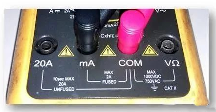
(1) Insert the black probe into the “COM” socket and the red probe into the “VΩ” socket (as shown in Figure 4);
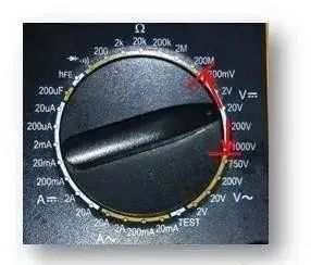
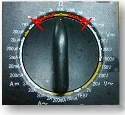
(2) Turn the range switch to the corresponding V range, then connect the test probes across the circuit being measured. The voltage at the point where the red probe is connected will be displayed on the screen along with its polarity (as shown in Figure 5).
(3) Notes:
If you are unsure of the voltage range to be measured, set the range switch to the highest setting, then adjust to the appropriate range based on the displayed value;
When not measuring, a small voltage range may show residual digits, which is normal and does not affect the test; if the high position shows “1” during measurement, it indicates that the range has been exceeded, and the range switch must be turned to a higher setting;
Do not exceed 1000V input voltage, as this may damage the meter’s circuitry;
When measuring high voltage circuits, be careful to avoid contact with the high voltage circuit.
AC Voltage Measurement
(1) Insert the black probe into the COM socket and the red probe into the VΩ socket (as shown in Figure 6);
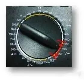
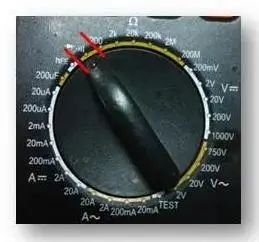
(2) Turn the range switch to the corresponding V~ range, then connect the test probes across the circuit being measured (as shown in Figure 7).
Notes:
(a) If you are unsure of the voltage range to be measured, set the range switch to the highest setting, then adjust to the appropriate range based on the displayed value;
(b) When not measuring, a small voltage range may show residual digits, which is normal and does not affect the test; if the high position shows “1” during measurement, it indicates that the range has been exceeded, and the range switch must be turned to a higher setting;
(c) Do not exceed 700Vrms input voltage, as this may damage the meter’s circuitry;
(d) When measuring high voltage circuits, be careful to avoid contact with the high voltage circuit.
DC Current Measurement
(1) Insert the black probe into the COM socket and the red probe into the mA socket (maximum 2A), or the red probe into the “20A” socket (maximum 20A) (as shown in Figure 8);
(2) Turn the range switch to the corresponding A range, then connect the meter in series with the circuit being measured. The measured current value and the polarity of the current at the red probe will be displayed on the screen (as shown in Figure 9).
Notes:
(a) If you are unsure of the current range to be measured, set the range switch to the highest setting, then adjust to the appropriate range based on the displayed value;
(b) If the LCD shows “1”, it indicates that the range has been exceeded, and the range switch must be turned to a higher setting;
(c) The maximum input current is 2A or 20A (depending on the position of the red probe). Excessive current may blow the fuse. When measuring in the 20A range, be cautious as this range has no protection. Continuous measurement of high current may cause the circuit to heat up, affecting measurement accuracy and potentially damaging the meter.
AC Current Measurement
(1) Insert the black probe into the “COM” socket and the red probe into the mA socket (maximum 2A), or the red probe into the “20A” socket (maximum 20A) (as shown in Figure 10);
(2) Turn the range switch to the corresponding A~ range, then connect the meter in series with the circuit being measured (as shown in Figure 11).
Notes:
(a) If you are unsure of the current range to be measured, set the range switch to the highest setting, then adjust to the appropriate range based on the displayed value;
(b) If the LCD shows “1”, it indicates that the range has been exceeded, and the range switch must be turned to a higher setting;
(c) The maximum input current is 2A or 20A (depending on the position of the red probe). Excessive current may blow the fuse. When measuring in the 20A range, be cautious as this range has no protection. Continuous measurement of high current may cause the circuit to heat up, affecting measurement accuracy and potentially damaging the meter.
Resistance Measurement (Ω)
(1) Insert the black probe into the “COM” socket and the red probe into the “VΩ” socket (as shown in Figure 12);
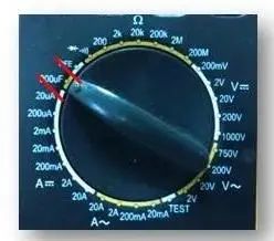
(2) Turn the range switch to the corresponding resistance range and connect the two probes across the resistor being measured (as shown in Figure 13).
Notes:
(a) If the resistance value exceeds the selected range, it will display “1”. In this case, the switch should be turned to a higher range; when measuring resistance values above 1 MΩ, the reading may take a few seconds to stabilize, which is normal for high resistance measurements;
(b) When the input terminals are open, it will display an overload condition;
(c) When measuring in-circuit resistance, ensure that all power sources to the circuit being measured are turned off and that all capacitors are fully discharged before proceeding;
(d) Do not apply voltage to the resistance range.
Diode/Continuity Testing
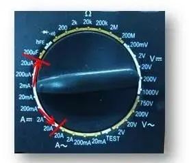
(1) Insert the black probe into the “COM” socket and the red probe into the “VΩ” socket (as shown in Figure 14);
(2) Set the range switch to the diode test position (as shown in Figure 15) and connect the probes to the diode under test, with the red probe connected to the anode of the diode. The reading will approximate the forward voltage drop of the diode;
(3) Connect the probes to two points in the circuit being tested. If the built-in buzzer sounds, it indicates that the resistance between the two points is below approximately (70±20)Ω.
Capacitance Measurement (C)
(1) Insert the red probe into the “COM” socket and the black probe into the “mA” socket (as shown in Figure 16);
(2) Set the range switch to the capacitance range (as shown in Figure 17);
(3) Connect the test probes across the capacitor terminals for measurement. When measuring electrolytic and tantalum capacitors, pay attention to polarity;
Notes:
(a) If the capacitor being measured exceeds the maximum value of the selected range, the display will only show “1”. In this case, the switch should be turned to a higher range;
(b) Before testing a capacitor, the display may show residual readings, which is normal and does not affect the measurement result;
(c) Ensure that the capacitor is fully discharged before testing large capacitors to prevent damage to the meter.
Live Wire Identification TEST
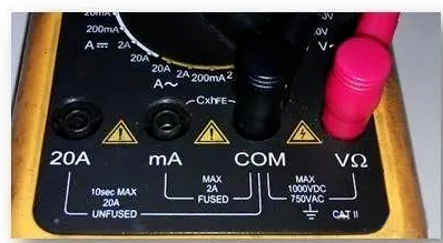
(1) Remove the black probe from the COM socket, leaving only the red probe in the VΩ socket (as shown in Figure 18);
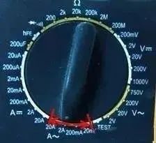
(2) Set the range switch to the TEST position and connect the red probe to the circuit being tested (as shown in Figure 19);
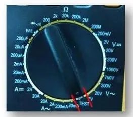
(3) If the display shows “1” and there is an audible alarm, the wire connected to the red probe is the live wire. If there is no change, it is the neutral wire;
Notes:
(a) This function only detects standard AC mains live wires AC-110V~AC-380V;
(b) Initial operations must be performed under the guidance of a supervisor;
(Source: Internet, copyright belongs to the original author)
You might also like
◆ The flexible use of a multimeter goes beyond just basic methods!
◆ One trick to determine wire breakpoints with a multimeter
◆ Essential! Multimeter user manual
◆ The use of a multimeter and its mnemonics, worth keeping!
Share · Win-win
The electrical community, a community with attitude