Table of Contents
1. RC522 Driver PrinciplesDriver Principles
2. Code Implementation
3. Summary & Precautions
01
—
RC522 Driver Principles
The RC522 is a highly integrated contactless read/write chip launched by NXP, designed specifically for Near Field Communication (NFC) and Radio Frequency Identification (RFID) applications. It is widely used in access control systems, payment terminals, smart homes, and other fields. It supports ISO/IEC 14443 Type A (such as MIFARE Classic series) and Type B (such as ID cards, some financial cards); it supports MIFARE Classic 1K/4K, Ultralight, DESFire tags, and is compatible with some functions of FeliCa.
The RC522 chip achieves RFID functionality through an external antenna, with the controller (51 microcontroller) using the SPI protocol to read and write the RC522 registers to control the antenna’s transmission and reception;
The typical operation flow is: (1) Card Search (REQA command) -> (2) Anti-collision (Get UID) -> (3) Select Card -> (4) Authenticate Key -> (5) Read/Write Data Block
Below are some performance characteristics of the RC522:
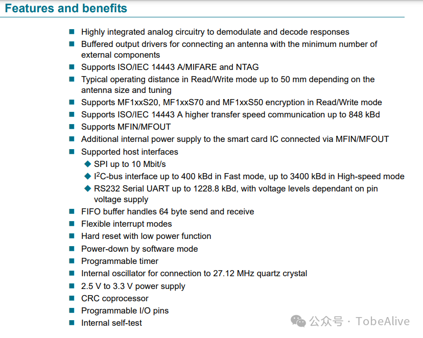
This includes supported protocols, SPI speed, control methods, buffer size, operating voltage, etc.
02
—
Code Implementation
Below is an example of driving the RC522
rc522.h
/******************rc522.h file***********/
#ifndef __RC522_H__
#define __RC522_H__

// RC522 SPI interface definitions

sbit     MF522_NSS  =    P1^7;
sbit     MF522_SCK  =    P1^6;
sbit     MF522_SI   =    P1^5;
sbit     MF522_SO   =    P1^4;
sbit     MF522_RST  =    P1^3;  //RC500 chip select

#define MAXRLEN  18

//Mifare_One card command words

#define PICC_REQIDL           0x26               // Search for cards in the antenna area that are not in sleep mode
#define PICC_REQALL           0x52               // Search for all cards in the antenna area
#define PICC_ANTICOLL1        0x93               // Select card
#define PICC_ANTICOLL2        0x95               // Anti-collision
#define PICC_AUTHENT1A        0x60               // Authenticate A key
#define PICC_AUTHENT1B        0x61               // Authenticate B key
#define PICC_READ             0x30               // Read block
#define PICC_WRITE            0xA0               // Write block
#define PICC_DECREMENT        0xC0               // Deduct
#define PICC_INCREMENT        0xC1               // Recharge
#define PICC_RESTORE          0xC2               // Transfer block data to buffer
#define PICC_TRANSFER         0xB0               // Save data in buffer
#define PICC_HALT             0x50               // Sleep

//MF522 command words

#define PCD_IDLE              0x00               // Cancel current command
#define PCD_AUTHENT           0x0E               // Authenticate key
#define PCD_RECEIVE           0x08               // Receive data
#define PCD_TRANSMIT          0x04               // Send data
#define PCD_TRANSCEIVE        0x0C               // Send and receive data
#define PCD_RESETPHASE        0x0F               // Reset
#define PCD_CALCCRC           0x03               // CRC calculation

#define DEF_FIFO_LENGTH       64

//MF522 register definitions

// PAGE 0
#define     RFU00                 0x00
#define     CommandReg            0x01
#define     ComIEnReg             0x02
#define     DivlEnReg             0x03
#define     ComIrqReg             0x04
#define     DivIrqReg             0x05
#define     ErrorReg              0x06
#define     Status1Reg            0x07
#define     Status2Reg            0x08
#define     FIFODataReg           0x09
#define     FIFOLevelReg          0x0A
#define     WaterLevelReg         0x0B
#define     ControlReg            0x0C
#define     BitFramingReg         0x0D
#define     CollReg               0x0E
#define     RFU0F                 0x0F
// PAGE 1
#define     RFU10                 0x10
#define     ModeReg               0x11
#define     TxModeReg             0x12
#define     RxModeReg             0x13
#define     TxControlReg          0x14
#define     TxAutoReg             0x15
#define     TxSelReg              0x16
#define     RxSelReg              0x17
#define     RxThresholdReg        0x18
#define     DemodReg              0x19
#define     RFU1A                 0x1A
#define     RFU1B                 0x1B
#define     MifareReg             0x1C
#define     RFU1D                 0x1D
#define     RFU1E                 0x1E
#define     SerialSpeedReg        0x1F
// PAGE 2
#define     RFU20                 0x20
#define     CRCResultRegM         0x21
#define     CRCResultRegL         0x22
#define     RFU23                 0x23
#define     ModWidthReg           0x24
#define     RFU25                 0x25
#define     RFCfgReg              0x26
#define     GsNReg                0x27
#define     CWGsCfgReg            0x28
#define     ModGsCfgReg           0x29
#define     TModeReg              0x2A
#define     TPrescalerReg         0x2B
#define     TReloadRegH           0x2C
#define     TReloadRegL           0x2D
#define     TCounterValueRegH     0x2E
#define     TCounterValueRegL     0x2F
// PAGE 3
#define     RFU30                 0x30
#define     TestSel1Reg           0x31
#define     TestSel2Reg           0x32
#define     TestPinEnReg          0x33
#define     TestPinValueReg       0x34
#define     TestBusReg            0x35
#define     AutoTestReg           0x36
#define     VersionReg            0x37
#define     AnalogTestReg         0x38
#define     TestDAC1Reg           0x39
#define     TestDAC2Reg           0x3A
#define     TestADCReg            0x3B
#define     RFU3C                 0x3C
#define     RFU3D                 0x3D
#define     RFU3E                 0x3E
#define     RFU3F       0x3F

#define MI_OK                          0
#define MI_NOTAGERR                    (-1)
#define MI_ERR                         (-2)

char PcdReset(void);
void PcdAntennaOn(void);
void PcdAntennaOff(void);
char PcdRequest(unsigned char req_code,unsigned char *pTagType);
char PcdAnticoll(unsigned char *pSnr);
char PcdComMF522(unsigned char Command,
                 unsigned char *pInData,
                 unsigned char InLenByte,
                 unsigned char *pOutData,
                 unsigned int  *pOutLenBit);
void WriteRawRC(unsigned char Address,unsigned char value);
unsigned char ReadRawRC(unsigned char Address);
void SetBitMask(unsigned char reg,unsigned char mask);
void ClearBitMask(unsigned char reg,unsigned char mask);
char M500PcdConfigISOType(unsigned char type);
void delay_10ms(unsigned int _10ms);
char PcdSelect(unsigned char *pSnr);
char PcdAuthState(unsigned char auth_mode,unsigned char addr,unsigned char *pKey,unsigned char *pSnr);
char PcdRead(unsigned char addr,unsigned char *pData);
char PcdWrite(unsigned char addr,unsigned char *pData);
char PcdValue(unsigned char dd_mode,unsigned char addr,unsigned char *pValue);
char PcdBakValue(unsigned char sourceaddr, unsigned char goaladdr);
void CalulateCRC(unsigned char *pIndata,unsigned char len,unsigned char *pOutData);
#endif
rc522.c
/******************** rc522.c file**************/
#include <reg52.h>
#include <intrins.h>
#include <string.h>

#include "rc522.h"

// Dedicated Timer2 SFR
sfr   RCAP2LH =   0xCA;
sfr   T2LH    =   0xCC;

/
// Function: Card Search
// Parameter Description: req_code[IN]: Card search method
//                0x52 = Search for all cards conforming to the 14443A standard in the induction area
//                0x26 = Search for cards that have not entered sleep mode
//          pTagType[OUT]: Card type code
//                0x4400 = Mifare_UltraLight
//                0x0400 = Mifare_One(S50)
//                0x0200 = Mifare_One(S70)
//                0x0800 = Mifare_Pro(X)
//                0x4403 = Mifare_DESFire
// Return: Returns MI_OK on success
/
char PcdRequest(unsigned char req_code,unsigned char *pTagType){
   char status;
   unsigned int  unLen;
   unsigned char ucComMF522Buf[MAXRLEN];
   ClearBitMask(Status2Reg,0x08);
   WriteRawRC(BitFramingReg,0x07);
   SetBitMask(TxControlReg,0x03);
   ucComMF522Buf[0] = req_code;
   status = PcdComMF522(PCD_TRANSCEIVE,ucComMF522Buf,1,ucComMF522Buf,&unLen);
   if ((status == MI_OK) && (unLen == 0x10))
   {
       *pTagType     = ucComMF522Buf[0];
       *(pTagType+1) = ucComMF522Buf[1];
   }
   else
   {   status = MI_ERR;   }
   return status;
}

/
// Function: Anti-collision
// Parameter Description: pSnr[OUT]: Card serial number, 4 bytes
// Return: Returns MI_OK on success
/
char PcdAnticoll(unsigned char *pSnr)
{
    char status;
    unsigned char i,snr_check=0;
    unsigned int  unLen;
    unsigned char ucComMF522Buf[MAXRLEN];


    ClearBitMask(Status2Reg,0x08);
    WriteRawRC(BitFramingReg,0x00);
    ClearBitMask(CollReg,0x80);

    ucComMF522Buf[0] = PICC_ANTICOLL1;
    ucComMF522Buf[1] = 0x20;

    status = PcdComMF522(PCD_TRANSCEIVE,ucComMF522Buf,2,ucComMF522Buf,&unLen);

    if (status == MI_OK)
    {
      for (i=0; i<4; i++)
         {
             *(pSnr+i)  = ucComMF522Buf[i];
             snr_check ^= ucComMF522Buf[i];
         }
         if (snr_check != ucComMF522Buf[i])
         {   status = MI_ERR;    }
    }

    SetBitMask(CollReg,0x80);
    return status;
}

/
// Function: Reset RC522
// Return: Returns MI_OK on success
/
char PcdReset(void){
    MF522_RST=1;
    _nop_();// No operation instruction
    MF522_RST=0;
    _nop_();
    MF522_RST=1;
     _nop_();
    WriteRawRC(CommandReg,PCD_RESETPHASE); // Write 0x0F to address 01
 _nop_();

    WriteRawRC(ModeReg,0x3D);            // Communicate with Mifare card, CRC initial value 0x6363, CRCPreset=01
    WriteRawRC(TReloadRegL,30);          // Timer reload value, divided into two 8-bit registers, initial value is 0x00
    WriteRawRC(TReloadRegH,0);
    WriteRawRC(TModeReg,0x8D);           // Internal timer settings 1000 1101, last four bits are the high four bits of TPrescalerReg
    WriteRawRC(TPrescalerReg,0x3E);      // Low 8 bits of TPrescaler, Ftimer = 6.78MHZ/TPreScaler
    WriteRawRC(TxAutoReg,0x40);
    return MI_OK;
}

/
// Function: Read RC522 register
// Parameter Description: Address[IN]: Register address
// Return: Read value
/
unsigned char ReadRawRC(unsigned char Address){
     unsigned char i, ucAddr;
     unsigned char ucResult=0;

     MF522_SCK = 0;
     MF522_NSS = 0;
     ucAddr = ((Address<<1)&0x7E)|0x80;

     for(i=8;i>0;i--)
     {
         MF522_SI = ((ucAddr&0x80)==0x80);
         MF522_SCK = 1;
         ucAddr <<= 1;
         MF522_SCK = 0;
     }

     for(i=8;i>0;i--)
     {
         MF522_SCK = 1;
         ucResult <<= 1;
         ucResult|=(bit)MF522_SO;
         MF522_SCK = 0;
     }

     MF522_NSS = 1;
     MF522_SCK = 1;
     return ucResult;
}

/
// Function: Write to RC522 register
// Parameter Description: Address[IN]: Register address
//          value[IN]: Value to write
/
void WriteRawRC(unsigned char Address, unsigned char value){
    unsigned char i, ucAddr;

    MF522_SCK = 0;
    MF522_NSS = 0;
    ucAddr = ((Address<<1)&0x7E);

    for(i=8;i>0;i--)
    {
        MF522_SI = ((ucAddr&0x80)==0x80);
        MF522_SCK = 1;
        ucAddr <<= 1;
        MF522_SCK = 0;
    }

    for(i=8;i>0;i--)
    {
        MF522_SI = ((value&0x80)==0x80);
        MF522_SCK = 1;
        value <<= 1;
        MF522_SCK = 0;
    }
    MF522_NSS = 1;
    MF522_SCK = 1;
}

/
// Function: Set RC522 register bit
// Parameter Description: reg[IN]: Register address
//          mask[IN]: Bit value to set
/
void SetBitMask(unsigned char reg,unsigned char mask)
{
    char tmp = 0x0;
    tmp = ReadRawRC(reg);
    WriteRawRC(reg,tmp | mask);  // set bit mask
}

/
// Function: Clear RC522 register bit
// Parameter Description: reg[IN]: Register address
//          mask[IN]: Bit value to clear
/
void ClearBitMask(unsigned char reg,unsigned char mask)
{
    char tmp = 0x0;
    tmp = ReadRawRC(reg);
    WriteRawRC(reg, tmp & ~mask);  // clear bit mask
}

/
// Function: Communicate with RC522 and ISO14443 card
// Parameter Description: Command[IN]: RC522 command word
//          pInData[IN]: Data sent to the card via RC522
//          InLenByte[IN]: Length of data sent in bytes
//          pOutData[OUT]: Data returned from the card
//          *pOutLenBit[OUT]: Length of returned data in bits
/
char PcdComMF522(unsigned char Command,
                 unsigned char *pInData,
                 unsigned char InLenByte,
                 unsigned char *pOutData,
                 unsigned int  *pOutLenBit)
{
    char status = MI_ERR;
    unsigned char irqEn   = 0x00;
    unsigned char waitFor = 0x00;
    unsigned char lastBits;
    unsigned char n;
    unsigned int i;
    switch (Command)
    {
       case PCD_AUTHENT:
          irqEn   = 0x12;
          waitFor = 0x10;
          break;
       case PCD_TRANSCEIVE:
          irqEn   = 0x77;
          waitFor = 0x30;
          break;
       default:
         break;
    }

    WriteRawRC(ComIEnReg,irqEn|0x80);
    ClearBitMask(ComIrqReg,0x80);
    WriteRawRC(CommandReg,PCD_IDLE);
    SetBitMask(FIFOLevelReg,0x80);

    for (i=0; i<InLenByte; i++)
    {   WriteRawRC(FIFODataReg, pInData[i]);    }
    WriteRawRC(CommandReg, Command);

    if (Command == PCD_TRANSCEIVE)
    {    SetBitMask(BitFramingReg,0x80);  }

//    i = 600;// Adjust based on clock frequency, maximum wait time for M1 card is 25ms
 i = 2000;//900,1100,1700,2000,2700
    do
    {
         n = ReadRawRC(ComIrqReg);
         i--;
    }
    while ((i!=0) && !(n&0x01) && !(n&waitFor));
    ClearBitMask(BitFramingReg,0x80);

    if (i!=0)
    {
         if(!(ReadRawRC(ErrorReg)&0x1B))
         {
             status = MI_OK;
             if (n & irqEn & 0x01)
             {   status = MI_NOTAGERR;   }
             if (Command == PCD_TRANSCEIVE)
             {
                n = ReadRawRC(FIFOLevelReg);
               lastBits = ReadRawRC(ControlReg) & 0x07;
                if (lastBits)
                {   *pOutLenBit = (n-1)*8 + lastBits;   }
                else
                {   *pOutLenBit = n*8;   }
                if (n == 0)
                {   n = 1;    }
                if (n > MAXRLEN)
                {   n = MAXRLEN;   }
                for (i=0; i<n; i++)
                {   pOutData[i] = ReadRawRC(FIFODataReg);    }

            }
         }
         else
         {   status = MI_ERR;   }
   }

   SetBitMask(ControlReg,0x80);           // stop timer now
   WriteRawRC(CommandReg,PCD_IDLE);
   return status;
}

// Turn on antenna
// There should be at least a 1ms interval between turning the antenna on or off
void PcdAntennaOn(){
    unsigned char i;
    i = ReadRawRC(TxControlReg);
    if (!(i & 0x03))
    {
        SetBitMask(TxControlReg, 0x03);
    }
}

// Turn off antenna
void PcdAntennaOff()
{
    ClearBitMask(TxControlReg, 0x03);
}

///
// Delay 10ms
///
void delay_10ms(unsigned int _10ms)
{
#ifndef NO_TIMER2
    RCAP2LH = RCAP2_10ms;
    T2LH    = RCAP2_10ms;

    TR2 = TRUE;
    while (_10ms--)
    {
     while (!TF2);
     TF2 = FALSE;
    }
    TR2 = FALSE;
#else
    while (_10ms--)
    {
     delay_50us(19);
     if (CmdValid)
         return;
     delay_50us(20);
     if (CmdValid)
         return;
     delay_50us(20);
     if (CmdValid)
         return;
     delay_50us(20);
     if (CmdValid)
         return;
     delay_50us(20);
     if (CmdValid )
         return;
     delay_50us(20);
     if (CmdValid)
         return;
     delay_50us(20);
     if (CmdValid)
         return;
     delay_50us(20);
     if (CmdValid)
         return;
     delay_50us(19);
     if (CmdValid)
         return;
    }
#endif
}
test.c
#include "rc522.h"

u16 count = 60, time=0;
u8 UID[5],Temp[4];

u8 UI[5]={0x27,0x7A,0xFB,0x34};
// Information for 6 cards
u8 UI1[5]={0xF1,0xB1,0x1B,0xD0};
u8 UI2[5]={0x51,0x7E,0xC9,0xCF};
u8 UI3[5]={0x31,0x11,0x1B,0xD0};
u8 UI4[5]={0x8C,0xF3,0xDA,0x0B};
u8 UI5[5]={0x89,0x31,0x17,0xBD};

void Rc522Test(void)
{
while(1)
 {
       if (PcdRequest(0x52, Temp) == MI_OK)
    {
      if (PcdAnticoll(UID) == MI_OK)
   {
   // Here is to check if it is one of the card serial numbers marked in the code, unless it is one of these five cards, do not execute the check
    if(strcmp(UID,UI)==0||strcmp(UID,UI4)==0||strcmp(UID,UI1)==0||strcmp(UID,UI2)==0||strcmp(UID,UI5)==0)
    {
     printf("card found");
    }
    else
    {
     printf("card not found");
    }
   }
    }

    }

}
03
—
Summary & Precautions
When using, first call thePcdReset function to reset the RC522 chip, call the PcdAntennaOff and PcdAntennaOn functions to perform reset line operations, then use M500PcdConfigISOType(‘A’) to configure the working mode, and finally call the Rc522Test function to identify the card.