51 Microcontroller
Hardware System
The 51 microcontroller (such as the Intel 8051 series and its derivatives) is a classic8bit microcontroller widely used in embedded system development.
1.Central Processing Unit (CPU)
Architecture: Based on an8bitCISC (Complex Instruction Set) architecture, with the core being theMCS51 instruction set.
Functional Modules:
Arithmetic Logic Unit (ALU): Performs arithmetic and logical operations.
Controller: Coordinates instruction decoding, timing control, and data flow.
Register Group:
Accumulator (ACC)
Program Status Word (PSW)
Stack Pointer (SP)
Data Pointer (DPTR) etc.
2.Memory Structure
Harvard Architecture: Program memory (ROM) and data memory (RAM) are physically separated.
Program Memory (ROM):
Stores fixed program code (such as4KB/8KB/64KB).
Types: MaskROM (8051),EPROM (8751),Flash (AT89C51).
Data Memory (RAM):
InternalRAM (128/256 bytes):
Low128 bytes: General registers, bit-addressable area, user data area.
High128 bytes (only enhanced version): Special function registers (SFR).
ExternalRAM: Expandable up to64KB.
3.Input/Output (I/O) Ports
4 8-bit bidirectionalI/O ports (P0P3):
P0: Multiplexed as data bus (D0D7) and low8 bit address bus (A0A7) when external memory is expanded.
P1: GeneralI/O, no multiplexing function.
P2: Acts as high8 bit address bus (A8A15) when external memory is expanded.
P3: Multiplexing functions (such as serial port, interrupt, timer pins).
4.Timer/Counter
Number: Typically2 (Timer0 andTimer1, enhanced versions likeSTC89C52 have3).
Operating Modes:
Mode0:13 bit counter
Mode1:16 bit counter
Mode2:Auto-reload8 bit counter
Mode3:Split mode (onlyTimer0)
Applications: Timer interrupts,PWM generation, event counting, etc.
5.Interrupt System
Interrupt Sources:
External interrupts (INT0,INT1)
Timer interrupts (TF0,TF1)
Serial port interrupts (TI/RI)
Priority: Two-level programmable priority.
Triggering Method: Low level or falling edge (external interrupts optional).
6.Serial Communication Interface (UART)
Full-duplex asynchronous communication, supporting4 working modes.
Baud Rate: Controlled by timer or independent baud rate generator.
Typical Applications: Communication withPC, sensors, or other microcontrollers.
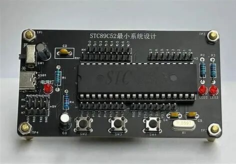
7.Clock Circuit
Clock Source: External crystal oscillator (such as11.0592MHz or12MHz) with oscillation capacitors.
Machine Cycle:12 clock cycles (traditional51) or1 clock cycle (enhanced versions likeSTC12 series).

8.Power Supply and Reset Circuit
Operating Voltage: Typically5V (some low-power models support3.3V).
Reset Circuit:
Power-on reset (RC circuit or dedicated reset chip).
Manual reset button.
9.Other Functional Modules (varies by model)
Watchdog Timer (WDT): Prevents program runaway.
PWM Output: Used for motor control,LED dimming.
ADC/DAC: Analog signal acquisition and output (such asSTC12C5A60S2).
Application Fields
Home appliance control (such as washing machines, air conditioners)
Industrial automation (sensor data acquisition)
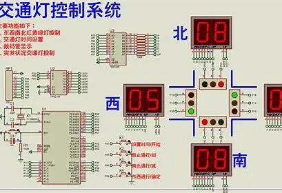
Teaching experiments (LED, digital tubes, button control)
Design Considerations
1.Power Stability: Filter capacitors (such as0.1μF ceramic capacitors) should be added.
2.Anti-interference: Long signal lines should be shielded or have pull-up resistors.
3.I/O Load Capacity: When driving high current devices, external driver circuits (such asULN2003) are required.
Example Code (to light upLED):
#include<reg52.h>
sbit LED=P1^0;//LED connected toP1.0
void main(){
while(1){
LED=0;// Low level lights up (common anode connection)
//LED=1;// High level turns off
}
}
END