
Wireless remote control modules are widely used in remote switches, vehicle unlocking, garage door control, access control systems, and other fields. A set of remote control receiving devices consists of a transmitting part and a receiving part. The transmitter encodes the control button pressed by the user into a radio frequency signal and then transmits the wireless signal. The receiver decodes the received wireless signal to obtain the signal corresponding to the control button, and then controls the corresponding circuit to operate.
The common communication frequencies between the transmitter and receiver are 315Mhz and 433Mhz. The transmitter can have one to four channels. The receiving circuits can be categorized based on their working methods into superheterodyne and superregenerative reception methods, and based on output types, they can be divided into powered output and non-powered output. This article will discuss these aspects of wireless remote control.
1. Remote Control Signal Reception Methods
Remote control modules can be divided into two types based on the signal reception method: superheterodyne receiving modules and superregenerative receiving modules. The principles of both are summarized as follows (just for reference, no need to understand):
1. Superregenerative
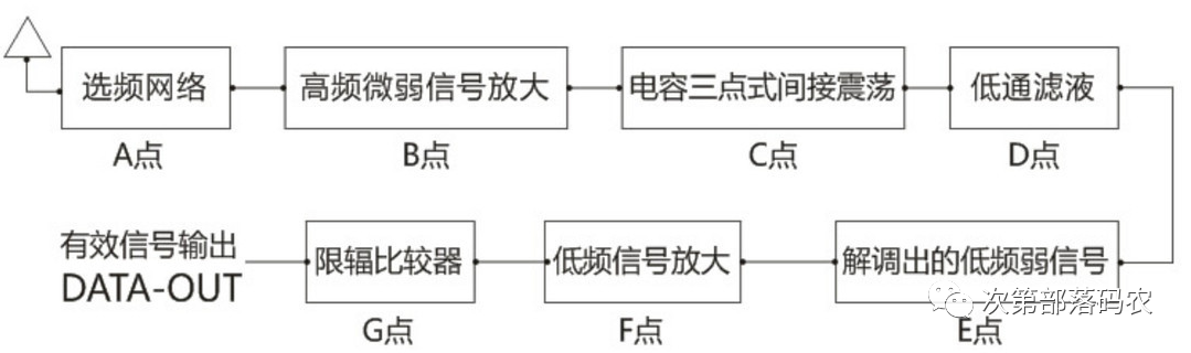
Superregenerative is a direct amplification receiver that utilizes positive feedback to amplify the processed information back to the input, then amplify and cycle it. The signal itself is processed directly without frequency conversion, having advantages such as simple circuitry, high sensitivity, compact size, and low cost, but also disadvantages such as unstable sensitivity, poor selectivity, and low anti-interference capability. Superregenerative detection circuits are commonly used in simple wireless remote communication devices (like alarm systems) that do not require high selectivity and signal-to-noise ratio.
2. Superheterodyne
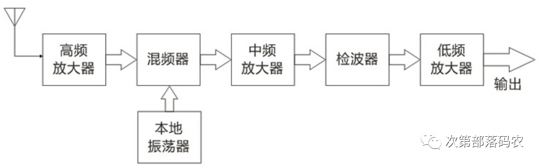
Superheterodyne demodulation circuits set up a local oscillator circuit to generate an oscillation signal, which mixes with the received carrier frequency signal to obtain an intermediate frequency (generally 465kHz) signal. After intermediate frequency amplification and detection, the data signal is demodulated. Because the carrier frequency is fixed, its circuit is simpler. The advantages of superheterodyne receivers include frequency stability, good anti-interference capability, and stable performance when used with microcontrollers, while their sensitivity is lower than that of superregenerative receivers, and their price is much higher.
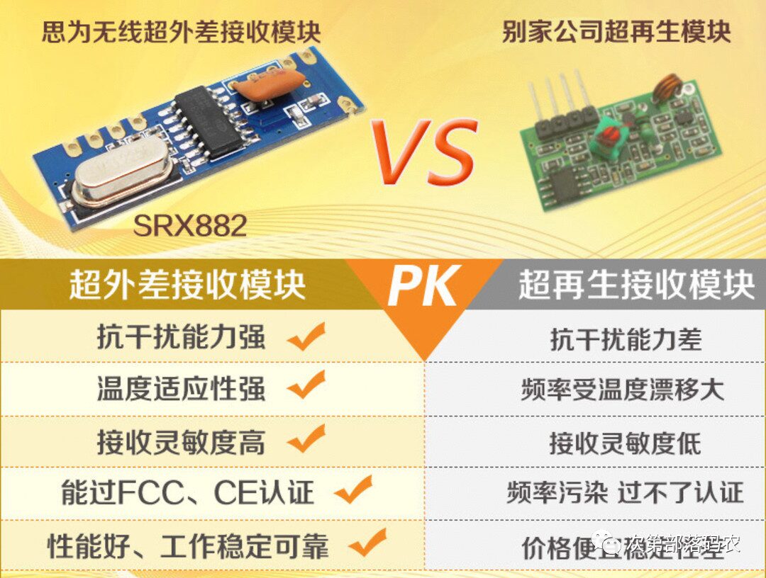
A comparison of superheterodyne receiving modules and superregenerative modules from a certain manufacturer:
2. Fixed Code vs Learning Code
How does the remote control know which module it controls? This involves understanding “fixed code” and “learning code”:
-
Fixed Code: The receiving module and remote control are one-to-one corresponding. When purchasing a receiving module, it comes with a specific remote control that cannot be controlled by other remotes. The advantage is stability, while the disadvantage is insecurity, as it is prone to duplication and easily copied.
-
Learning Code: Before use, the wireless remote must be aimed at the learning button on the receiving module to complete the pairing process. You can customize which button controls which module, and the duplication rate and confidentiality are relatively better.
Both fixed and learning codes are not very secure due to their limited number of codes, leading to the emergence of “rolling codes”, which use longer encoding methods, typically used in identity verification scenarios, such as car remote controls and bank wireless locks.
To determine whether a remote control module uses a fixed code or a learning code, simply open the casing and look at the chip inside: fixed code wireless remote controls mainly use coding chips like 2260/2262/2264, paired with receiving and decoding chips like 2270/2272/2294; learning code wireless remote controls mainly use learning code chips like 1527/2240/101.
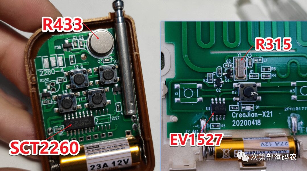
For example, the left remote control in the image is a 433Mhz fixed code remote, while the right one is a 315Mhz learning code remote.
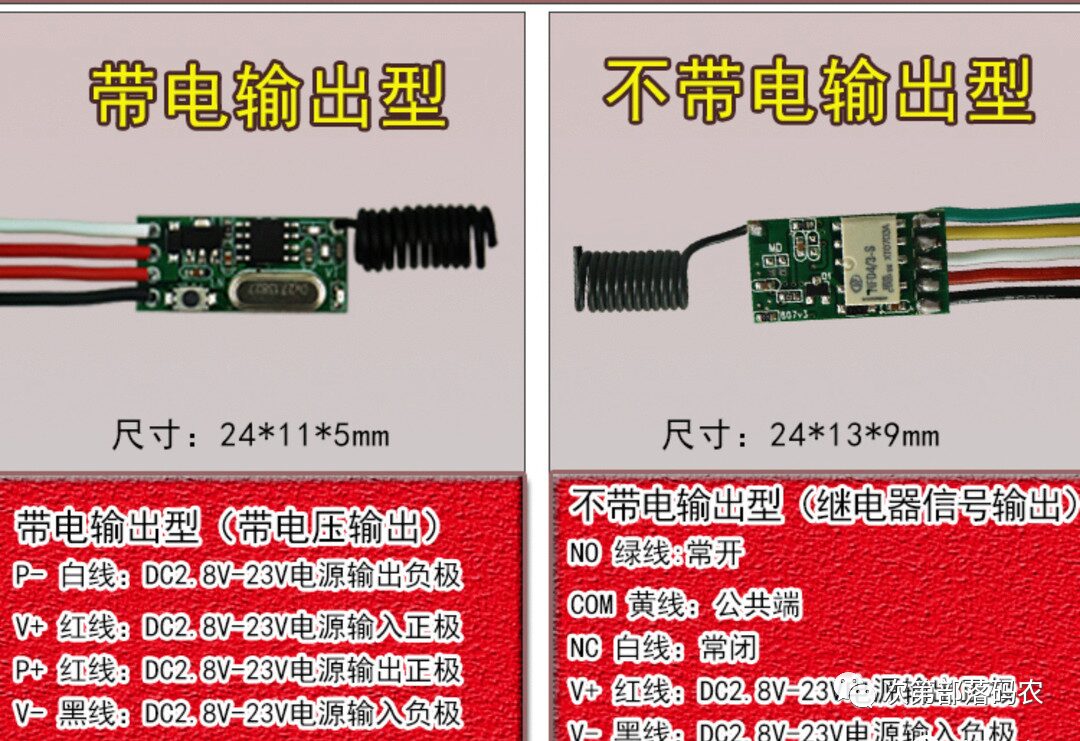
3. Powered Output vs Non-Powered Output
The receiving module can be categorized based on output type into powered output and non-powered output. Powered output means the output pin outputs low/high levels, with weak driving capability, usually unable to drive loads directly, often using MOS transistors to enhance driving capability. Non-powered output means adding a relay to the output stage of the receiving module, with actual output pins being the relay’s NO, COM, NC pins. By flying two wires on a non-powered output module, it can achieve powered output.
4. Superheterodyne Transmitting/Receiving Modules
The above introduced are theoretical knowledge. Now, let’s look at some transmitting and receiving module physical examples to understand their functions and usage.
1. Receiving Module
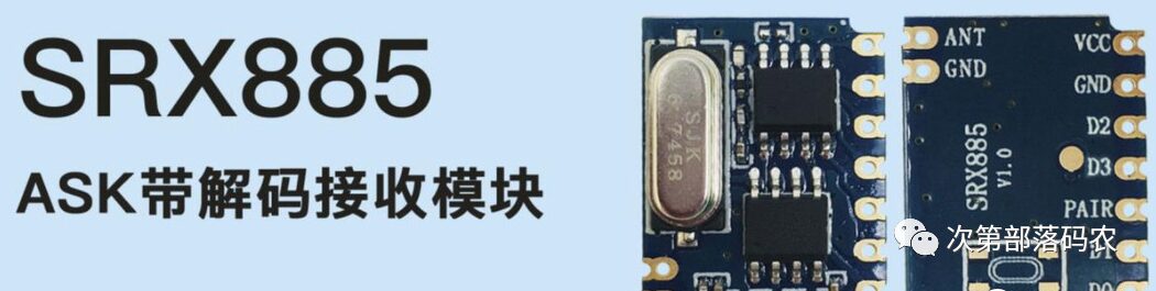
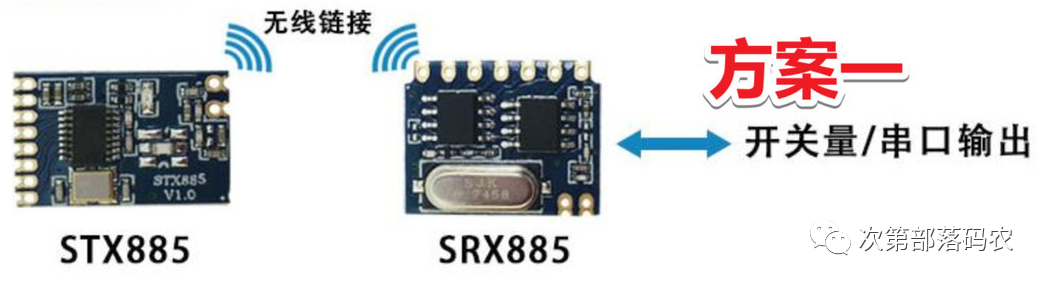
Taking the SRX855 ASK decoding receiving module as an example, ASK is a modulation method, and decoding means there is no need to use a decoding chip for secondary development; it can be used directly. The datasheet states that this module “automatically recognizes and learns common encoding methods such as 2262, 1527, 2240,” meaning that both fixed and learning code remote controls can be paired. ▲
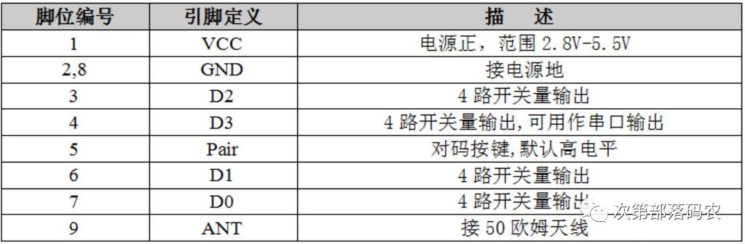
The 5th pin is the pairing button, and an external button is used for pairing/clearing and switching working modes. ▲
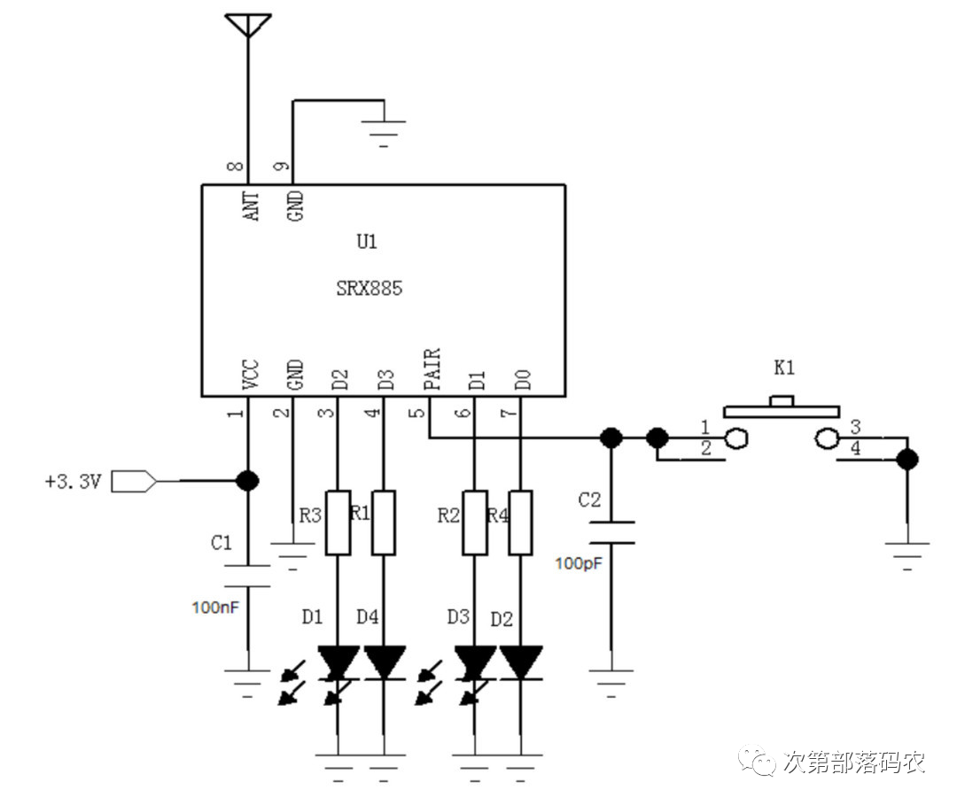
The typical application circuit is shown in the above image, D1-D4 are 4-channel output, with weak driving capability, only a few tens of milliamperes; it can light up an LED, but it is insufficient to drive a motor or solenoid.
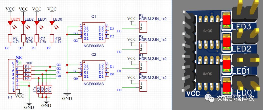
I plan to use it for wireless control of four solenoids, so I designed to use an NCE6005 dual MOS transistor to enhance the module’s driving capability. The right side shows a 3D preview of the PCB. After prototyping at JLCPCB, I soldered the wireless receiving module and the MOS driving board together with pin headers. The actual measured working current can reach several hundred milliamperes when the motor is stalled, powered by a 3.7V standard lithium battery.
2. Transmitting Module
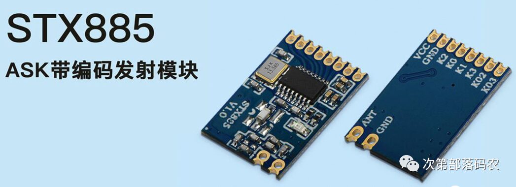
The paired STX885 is an ASK encoding transmitting module containing an ev1527 digital encoding circuit, supporting 6 button inputs. ▲

In practical applications, you can use the paired transmitting module or any ordinary remote control.
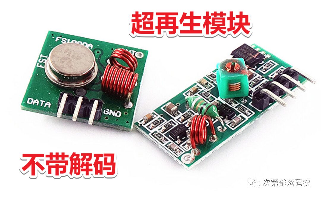
5. Superregenerative Transmitting/Receiving Modules
If there is no rectangular 18-pin chip on the superregenerative transmitting/receiving module, it means it is not a decoding type and requires a microcontroller or 2262/2272 chips for encoding and decoding.
For DIY purposes, we generally choose a decoding-capable receiving module + wireless remote control kit.
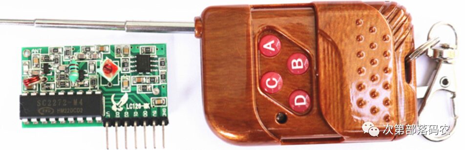
PT2262/PT2272 is a low-power, low-cost general-purpose encoding/decoding circuit manufactured by the Taiwanese company Pu Cheng using CMOS technology. The encoding chip PT2262 sends out encoded signals composed of address code, data code, and synchronization code, while the decoding chip PT2272 outputs a high level on its VT pin only after its address code has been verified twice. Meanwhile, the corresponding data pins also output a high level. If the sending end continuously holds down a button, the encoding chip will continuously transmit.
The data output of PT2272 varies based on its suffix, with two modes: “temporary storage” and “latching”. The suffix “M” indicates “temporary storage”, while “L” indicates “latching”. The data output can be 0, 2, 4, or 6, for example, PT2272-M4 indicates a 4-bit temporary storage remote control receiving chip.
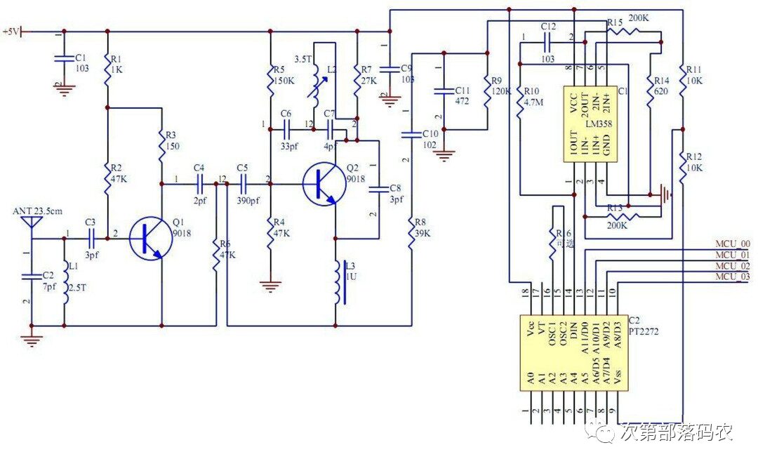
The principle of the PT2272 receiving module is shown in the above image. Inductors L1 and L3 are used to change the working frequency of 315Mhz/433Mhz. The received signal is amplified by operational amplifier LM358 and input to pin 14 of PT2272, which then decodes the received signal. D0-D3 output the corresponding levels. The direct output current of the superregenerative receiving module is also small, and to enhance output capability, you can use previously mentioned transistors or MOS amplification circuits.