Click the “Yudaosource” above and select “Set as Star”
Regardless of the old waves or the new waves?
The waves that can roll are the good ones!
Articles updated daily at 8:55, losing a bit of hair every day…
Source Code Boutique Column
-
Original | Java 2020 Super God Road, very intense~
-
Open-source projects with detailed Chinese annotations
-
RPC framework Dubbo source code analysis
-
Network application framework Netty source code analysis
-
Message middleware RocketMQ source code analysis
-
Database middleware Sharding-JDBC and MyCAT source code analysis
-
Job scheduling middleware Elastic-Job source code analysis
-
Distributed transaction middleware TCC-Transaction source code analysis
-
Eureka and Hystrix source code analysis
-
Java concurrency source code
Source: juejin.im/post/6844903490595061767
-
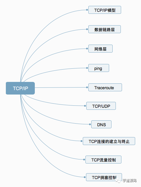
1. TCP/IP Model -
2. Data Link Layer -
3. Network Layer -
4. Ping -
5. Traceroute -
6. TCP/UDP -
7. DNS -
8. Establishing and Terminating TCP Connections -
9. TCP Flow Control -
10. TCP Congestion Control
1. TCP/IP Model
The TCP/IP protocol model (Transmission Control Protocol/Internet Protocol) includes a series of network protocols that form the foundation of the internet and is the core protocol of the Internet.
The reference model based on TCP/IP divides the protocols into four layers: Link Layer, Network Layer, Transport Layer, and Application Layer. The diagram below shows the correspondence between the TCP/IP model and the OSI model layers.
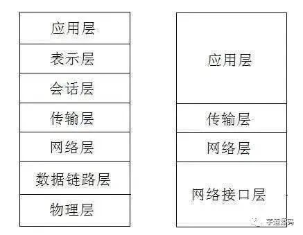
The TCP/IP protocol suite is layered from top to bottom, with each layer encapsulating the next. The topmost layer is the Application Layer, which contains familiar protocols like HTTP and FTP. The second layer is the Transport Layer, where the well-known TCP and UDP protocols reside. The third layer is the Network Layer, where the IP protocol is located, responsible for adding IP addresses and other data to determine the transmission target. The fourth layer is the Data Link Layer, which adds an Ethernet protocol header to the data being transmitted and performs CRC encoding to prepare for the final data transfer.
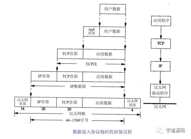
The above diagram clearly illustrates the role of each layer in the TCP/IP protocol, while the communication process of the TCP/IP protocol corresponds to the process of data stacking and unstacking. In the stacking process, the data sender continuously encapsulates headers and trailers at each layer, adding some transmission information to ensure it can reach its destination. In the unstacking process, the data receiver continuously removes headers and trailers at each layer to obtain the final transmitted data.
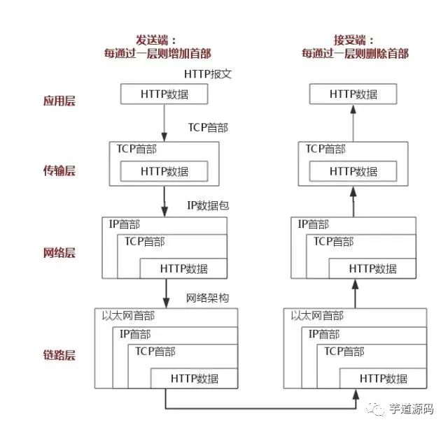
The above diagram uses the HTTP protocol as an example to explain in detail.
2. Data Link Layer
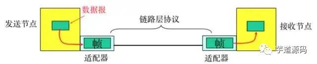
The Physical Layer is responsible for the conversion between the 0 and 1 bit streams and the voltage levels of physical devices or the flashing of light. The Data Link Layer is responsible for dividing the 0 and 1 sequences into data frames for transmission from one node to the adjacent one, which are uniquely identified by MAC addresses (MAC, physical address, each host has a MAC address).
-
Encapsulation into frames: Add headers and trailers to the network layer datagram to encapsulate it into a frame, where the frame header includes the source MAC address and destination MAC address. -
Transparent transmission: Zero-bit padding, escape characters. -
Reliable transmission: Rarely used on low-error-rate links, but wireless links (WLAN) guarantee reliable transmission. -
Error detection (CRC): The receiver checks for errors, and if an error is detected, the frame is discarded.
3. Network Layer
1. IP Protocol
The IP protocol is the core of the TCP/IP protocol, and all TCP, UDP, ICMP, and IGMP data is transmitted in IP data format. It is important to note that IP is not a reliable protocol, meaning that the IP protocol does not provide a mechanism for handling undelivered data, which is considered the responsibility of the upper-layer protocols: TCP or UDP.
1.1 IP Address
In the Data Link Layer, we generally identify different nodes by MAC addresses, while at the IP layer, we also need a similar address identifier, which is the IP address.
A 32-bit IP address is divided into network bits and address bits, which reduces the number of records in the routing table of routers. With the network address, terminals with the same network address can be confined to the same range, allowing the routing table to maintain only one direction for this network address to find the corresponding terminals.
Class A IP Address: 0.0.0.0~127.0.0.0
Class B IP Address: 128.0.0.1~191.255.0.0
Class C IP Address: 192.168.0.0~239.255.255.0
1.2 IP Protocol Header
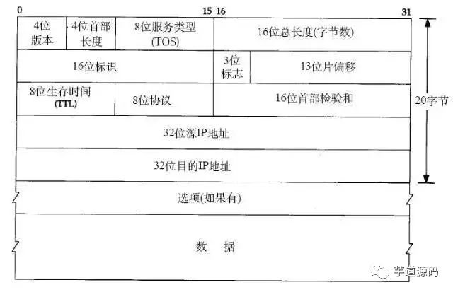
Here we only introduce: the eight-bit TTL field. This field specifies how many routers the packet can pass through before being discarded. Each time an IP packet passes through a router, its TTL value decreases by 1, and when the TTL value reaches zero, it is automatically discarded.
The maximum value of this field is 255, meaning a protocol packet can pass through a router 255 times before being discarded. Depending on the system, this number may vary, generally being 32 or 64.
2. ARP and RARP Protocols
ARP is a protocol for obtaining MAC addresses based on IP addresses.
The ARP (Address Resolution Protocol) is a resolution protocol, where the host is initially unaware of which interface corresponds to the IP address. When a host wants to send an IP packet, it first checks its ARP cache (a cache of IP-MAC address mappings).
If the queried IP-MAC mapping does not exist, the host sends an ARP broadcast packet to the network, which includes the IP address to be queried. All hosts that receive this broadcast packet will check their IP addresses, and if one of the hosts finds that it meets the condition, it prepares an ARP packet containing its MAC address to send back to the broadcasting host.
After the broadcasting host receives the ARP packet, it updates its ARP cache (the place where the IP-MAC mapping is stored). The broadcasting host will then use the new ARP cache data to prepare the data link layer packet for transmission.
The RARP protocol works in the opposite manner, and will not be elaborated here.
3. ICMP Protocol
The IP protocol is not a reliable protocol; it does not guarantee data delivery. Therefore, the task of ensuring data delivery should be handled by other modules. One important module is the ICMP (Internet Control Message Protocol). ICMP is not a high-level protocol, but rather a protocol at the IP layer.
When errors occur in the transmission of IP packets, such as unreachable hosts or unreachable routes, the ICMP protocol packages the error information and sends it back to the host, providing an opportunity for the host to handle the error. This is why it is said that protocols built on top of the IP layer can potentially achieve reliability.
4. Ping
Ping can be considered the most famous application of ICMP, and is part of the TCP/IP protocol. The “ping” command can be used to check network connectivity, which helps us analyze and determine network faults effectively.
For example, when we cannot access a certain website, we usually ping that website. The ping command returns some useful information, typically as follows:
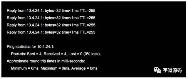
The word ping originates from sonar positioning, and the function of this program is indeed similar; it uses ICMP packets to detect whether another host is reachable. The principle is to send a request using an ICMP packet with a type code of 0, and the host receiving the request responds with an ICMP packet of type code 8.
5. Traceroute
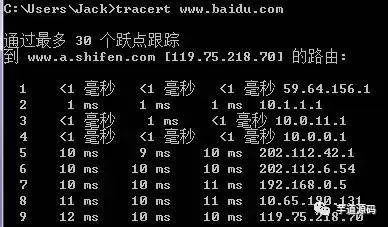
Traceroute is an important tool for detecting the routing situation between a host and the destination host, and is also one of the most convenient tools.
The principle of Traceroute is very interesting. After receiving the destination host’s IP, it first sends a UDP packet with TTL=1 to the destination host. The first router that receives this packet automatically reduces the TTL by 1, and when the TTL becomes 0, the router discards the packet and generates an ICMP message indicating that the host is unreachable. After the host receives this message, it sends a UDP packet with TTL=2 to the destination host, prompting the second router to send an ICMP message back to the host. This process continues until the destination host is reached, allowing Traceroute to obtain the IP addresses of all the routers in between.
6. TCP/UDP
TCP and UDP are both transport layer protocols, but they have different characteristics and applications. Below is a comparative analysis in tabular form.
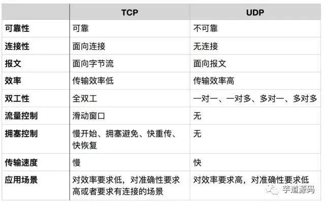
Message-oriented
The message-oriented transmission mode means that the application layer hands over a message of a certain length to UDP, and UDP sends it as is, meaning that the application must choose an appropriately sized message. If the message is too long, the IP layer needs to fragment it, reducing efficiency. If it is too short, it can lead to a small IP.
Byte stream-oriented
In the byte stream-oriented mode, although the interaction between the application and TCP occurs one data block at a time (of varying sizes), TCP treats the application as a continuous, unstructured byte stream. TCP has a buffer, and when the data block sent by the application is too long, TCP can split it into shorter segments before sending.
Regarding congestion control and flow control, these are key aspects of TCP, which will be explained later.
Applications of TCP and UDP protocols
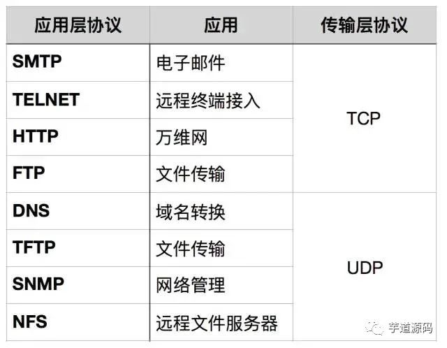
When should TCP be used?
When there are requirements for the quality of network communication, for example: when the entire data must be accurately delivered to the other party, this is often used in applications that require reliability, such as protocols for transferring files like HTTP, HTTPS, FTP, as well as email transfer protocols like POP, SMTP.
When should UDP be used?
When the requirements for the quality of network communication are not high, and speed is prioritized, UDP can be used.
7. DNS
DNS (Domain Name System) is a distributed database on the internet that maps domain names to IP addresses, allowing users to access the internet more conveniently without needing to remember machine-readable IP number strings. The process of obtaining the IP address corresponding to a hostname through the hostname is called domain name resolution (or hostname resolution). The DNS protocol runs on top of the UDP protocol, using port number 53.
8. Establishing and Terminating TCP Connections
1. Three-way Handshake
TCP is connection-oriented. Before either party sends data, a connection must first be established between both parties. In the TCP/IP protocol, the TCP protocol provides reliable connection services, and the connection is initialized through a three-way handshake. The purpose of the three-way handshake is to synchronize the sequence numbers and acknowledgment numbers of both parties and exchange TCP window size information.
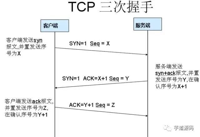
First handshake: Establishing a connection. The client sends a connection request segment, setting SYN to 1 and Sequence Number to x; then, the client enters the SYN_SEND state, waiting for the server’s acknowledgment;
Second handshake: The server receives the SYN segment. The server must acknowledge the client’s SYN segment, setting Acknowledgment Number to x+1 (Sequence Number+1); at the same time, it must send its own SYN request, setting SYN to 1 and Sequence Number to y; the server combines all the above information into one segment (the SYN+ACK segment) and sends it to the client, entering the SYN_RECV state;
Third handshake: The client receives the server’s SYN+ACK segment. It then sets the Acknowledgment Number to y+1 and sends an ACK segment to the server. After this segment is sent, both the client and server enter the ESTABLISHED state, completing the TCP three-way handshake.
Why three-way handshake?
To prevent an invalid connection request segment from suddenly reaching the server and causing errors.
A specific example of an “invalid connection request segment” can occur in a situation where the first connection request segment sent by the client does not get lost but remains stuck at a network node for a long time, arriving at the server after the connection has been released. This would be an already invalid segment. However, if the server receives this invalid connection request segment, it mistakenly assumes it is a new connection request from the client.
Thus, it sends a confirmation segment to the client, agreeing to establish a connection. If the “three-way handshake” is not used, as soon as the server sends the confirmation, a new connection would be established. Since the client has not made a connection request, it would ignore the server’s confirmation and would not send data to the server. However, the server would think that a new transport connection has been established and would wait for the client to send data. This would waste many resources on the server. The “three-way handshake” method can prevent this phenomenon. For instance, in the above situation, the client would not send a confirmation to the server. The server, not receiving the confirmation, would know that the client did not request to establish a connection.
2. Four-way Teardown
After the client and server establish a TCP connection through the three-way handshake, when the data transmission is complete, the TCP connection must be terminated. This leads to the mysterious “four-way teardown.”
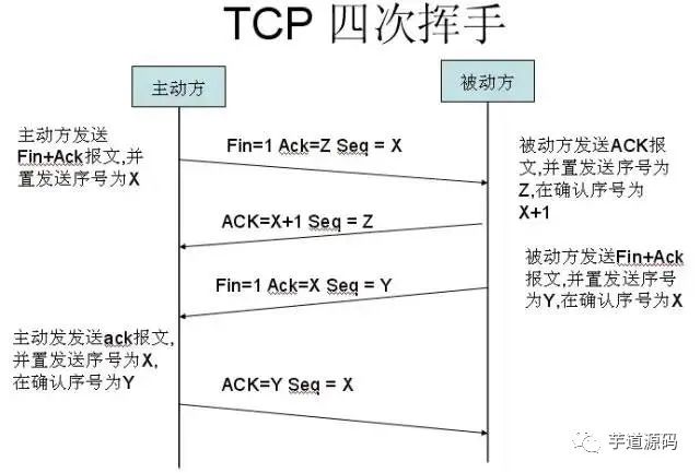
First teardown: Host 1 (which can be either the client or server) sets the Sequence Number and sends a FIN segment to Host 2; at this point, Host 1 enters the FIN_WAIT_1 state; this indicates that Host 1 has no data to send to Host 2;
Second teardown: Host 2 receives the FIN segment sent by Host 1 and sends an ACK segment back to Host 1 with the Acknowledgment Number set to the Sequence Number plus 1; Host 1 enters the FIN_WAIT_2 state; Host 2 informs Host 1 that it agrees to the shutdown request;
Third teardown: Host 2 sends a FIN segment to Host 1, requesting to close the connection, while Host 2 enters the LAST_ACK state;
Fourth teardown: Host 1 receives the FIN segment sent by Host 2 and sends an ACK segment back to Host 2, then Host 1 enters the TIME_WAIT state; after Host 2 receives the ACK segment from Host 1, it closes the connection; at this point, Host 1 waits for 2MSL, and if it still does not receive a reply, it confirms that the Server has closed properly, allowing Host 1 to also close the connection.
Why four-way teardown?
The TCP protocol is a connection-oriented, reliable, byte-stream-based transport layer communication protocol. TCP operates in full-duplex mode, meaning that when Host 1 sends a FIN segment, it only indicates that Host 1 has no data to send anymore; it informs Host 2 that its data has been completely sent. However, at this point, Host 1 can still receive data from Host 2; when Host 2 returns the ACK segment, it indicates that it knows Host 1 has no data to send, but Host 2 can still send data to Host 1; when Host 2 also sends a FIN segment, it indicates that Host 2 has no data to send either, and it informs Host 1 that it has no data to send, after which both will happily terminate this TCP connection.
Why wait for 2MSL?
MSL: Maximum Segment Lifetime, which is the longest time any segment can exist in the network before being discarded. There are two reasons:
-
To ensure that the TCP protocol’s full-duplex connection can be closed reliably -
To ensure that any duplicate segments from this connection disappear from the network
The first point: If Host 1 directly goes to CLOSED, and due to the unreliability of the IP protocol or other network reasons, Host 2 does not receive Host 1’s last ACK reply. Then Host 2 will continue to send FIN after a timeout, but since Host 1 has already CLOSED, it will not find the corresponding connection for the retransmitted FIN. Therefore, Host 1 should not directly enter CLOSED, but should remain in TIME_WAIT, allowing it to ensure that it receives the ACK for the FIN it sent, and only then correctly close the connection.
The second point: If Host 1 directly goes to CLOSED and then initiates a new connection to Host 2, we cannot guarantee that this new connection will have a different port number than the one that was just closed. In other words, it is possible for the new connection to have the same port number as the old connection. Generally, this will not cause any issues, but special cases can arise: if the new connection and the already closed old connection have the same port number, and some data from the previous connection is still lingering in the network, this delayed data may arrive at Host 2 after the new connection is established. Since the new connection and old connection share the same port number, the TCP protocol will consider that delayed data as belonging to the new connection, which could confuse it with the actual new connection data packets. Therefore, the TCP connection must wait in the TIME_WAIT state for 2MSL to ensure that all data from this connection disappears from the network.
9. TCP Flow Control
If the sender sends data too quickly, the receiver may not be able to keep up, resulting in data loss. Flow control is about ensuring that the sender’s transmission rate is not too fast, allowing the receiver to keep up with reception.
The sliding window mechanism can conveniently implement flow control on a TCP connection.
Assuming A sends data to B. At the time of connection establishment, B informs A: “My receive window is rwnd = 400” (where rwnd represents the receiver window). Therefore, the sender’s sending window cannot exceed the value of the receive window provided by the receiver. Note that the TCP window is measured in bytes, not segments. Assuming each segment is 100 bytes long, and the initial value of the data segment sequence number is set to 1. Uppercase ACK indicates the acknowledgment flag in the header, while lowercase ack indicates the acknowledgment field value.
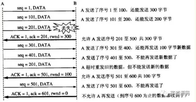
From the diagram, we can see that B performed flow control three times. The first time it reduced the window to rwnd = 300, the second time to rwnd = 100, and finally to rwnd = 0, meaning the sender is no longer allowed to send data. This state of pausing the sender will last until Host B sends a new window value.
TCP sets a persistent timer for each connection. As long as one party of the TCP connection receives a zero-window notification from the other party, it starts the persistent timer. If the persistent timer expires, it sends a zero-window probe segment (carrying 1 byte of data), prompting the receiving party to reset the persistent timer.
10. TCP Congestion Control
The sender maintains a congestion window cwnd (congestion window) as a state variable. The size of the congestion window depends on the level of network congestion and changes dynamically. The sender sets its sending window equal to the congestion window.
The principle of controlling the congestion window is: as long as there is no congestion in the network, the congestion window increases slightly to send more packets. But if congestion occurs, the congestion window decreases to reduce the number of packets injected into the network.
The slow-start algorithm:
When a host starts sending data, if a large amount of data is injected into the network immediately, it may cause network congestion because the network load is unknown at that moment. Therefore, a better method is to probe first, that is, gradually increase the sending window from small to large, meaning gradually increase the congestion window value.
Typically, when starting to send segments, set the congestion window cwnd to the value of one maximum segment size MSS. After receiving an acknowledgment for a new segment, increase the congestion window by at most one MSS. This gradual increase in the sender’s congestion window cwnd allows packets to be injected into the network at a more reasonable rate.
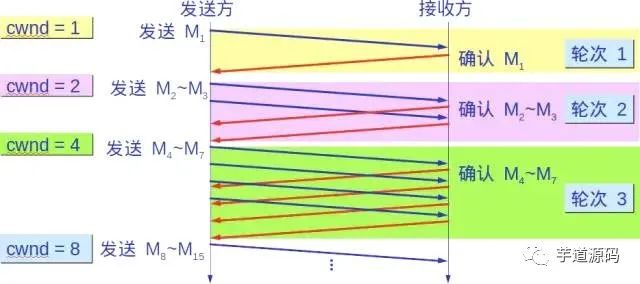
After each transmission round, the congestion window cwnd doubles. The time for a transmission round is actually the round-trip time RTT. However, the term “transmission round” emphasizes that all segments allowed by the congestion window cwnd are sent continuously and acknowledgments for the last byte sent are received.
Moreover, the “slow” in slow start does not refer to the slow growth rate of cwnd, but rather to the fact that when TCP starts sending segments, it first sets cwnd to 1, allowing the sender to only send one segment at the start (to probe the network’s congestion situation), and then gradually increase cwnd.
To prevent the congestion window cwnd from growing too large and causing network congestion, a slow start threshold ssthresh state variable is also set. The use of the slow start threshold ssthresh is as follows:
-
When cwnd < ssthresh, use the above slow start algorithm. -
When cwnd > ssthresh, stop using the slow start algorithm and switch to the congestion avoidance algorithm. -
When cwnd = ssthresh, either the slow start algorithm or the congestion avoidance algorithm can be used.
Congestion avoidance
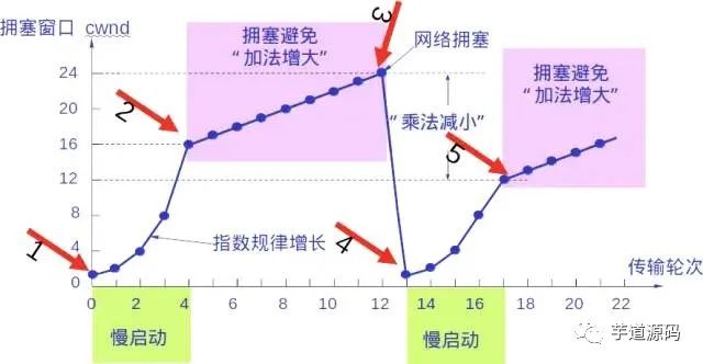
Gradually increase the congestion window cwnd, meaning that for each round-trip time RTT, the sender’s congestion window cwnd increases by 1 instead of doubling. This way, the congestion window cwnd grows slowly in a linear manner, much slower than the growth rate of the congestion window in the slow start algorithm.

Whether in the slow start phase or the congestion avoidance phase, as long as the sender determines that network congestion has occurred (based on the lack of acknowledgment), it should set the slow start threshold ssthresh to half of the sender’s window value at the time of congestion (but not less than 2). Then, reset the congestion window cwnd to 1 and execute the slow start algorithm.
The purpose of this is to quickly reduce the number of packets sent into the network, giving the congested router enough time to process the packets queued up.
The following diagram illustrates the process of congestion control with specific values. Now the size of the sending window is equal to that of the congestion window.
2. Fast Retransmit and Fast Recovery
Fast Retransmit
The fast retransmit algorithm requires the receiver to immediately send a duplicate acknowledgment for each out-of-order segment received (to allow the sender to know early that a segment has not arrived) rather than wait until it sends data to send an acknowledgment.
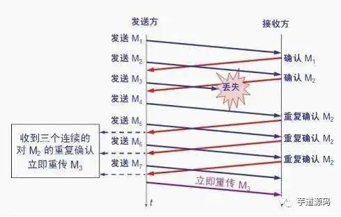
After receiving M1 and M2, the receiver sends acknowledgments for both. Now assume the receiver did not receive M3 but then received M4.
Clearly, the receiver cannot acknowledge M4 because it is an out-of-order segment. According to reliable transmission principles, the receiver can either do nothing or send a duplicate acknowledgment for M2 at an appropriate time.
However, according to the fast retransmit algorithm, the receiver should promptly send a duplicate acknowledgment for M2, allowing the sender to know early that segment M3 has not reached the receiver. The sender then sends M5 and M6. After receiving these two segments, the receiver must also send a duplicate acknowledgment for M2 again. In this way, the sender receives a total of four acknowledgments for M2, three of which are duplicates.
The fast retransmit algorithm also stipulates that as soon as the sender receives three duplicate acknowledgments, it should immediately retransmit the unacknowledged segment M3 without waiting for the retransmission timer for M3 to expire.
By retransmitting unacknowledged segments early, the overall network throughput can be increased by about 20%.
Fast Recovery
Used in conjunction with fast retransmit, the fast recovery algorithm has the following two key points:
-
When the sender receives three consecutive duplicate acknowledgments, it executes the “multiplicative decrease” algorithm, halving the slow-start threshold ssthresh. -
Unlike slow start, the sender does not set the congestion window cwnd to 1; instead, it sets the cwnd to the value of the slow-start threshold ssthresh after halving, and then starts executing the congestion avoidance algorithm (“additive increase”), allowing the congestion window to increase gradually and linearly.
Welcome to join my knowledge circle to discuss architecture and exchange source code. To join, long press the QR code below:
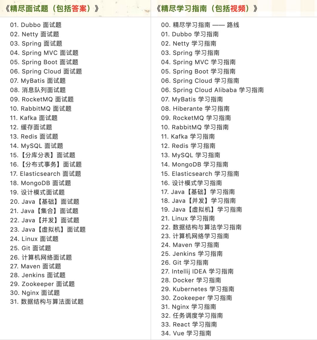
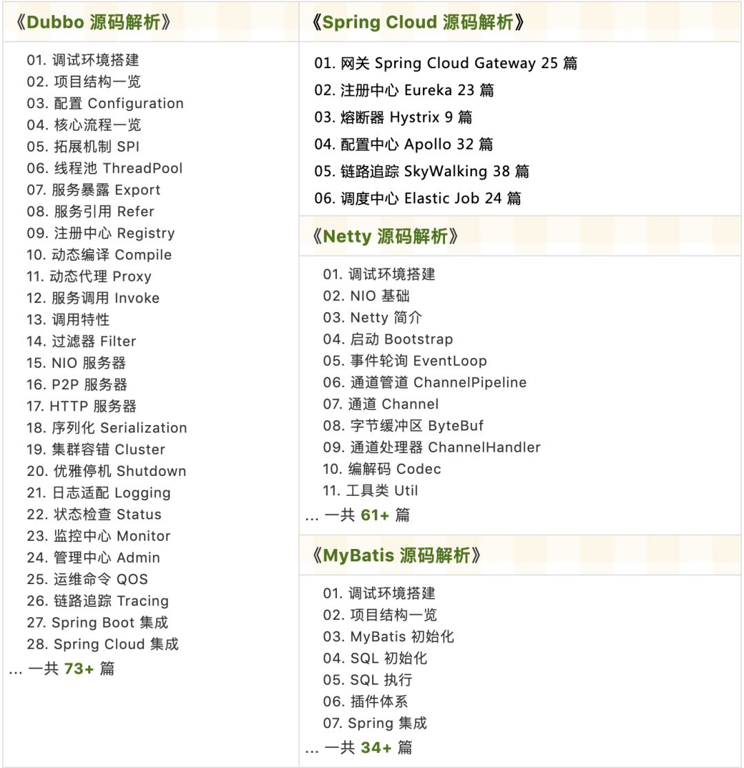
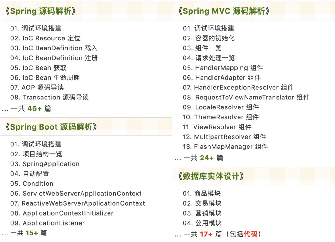
Source code analysis has been updated in the knowledge circle as follows:
Recently updated the “Yudaosource SpringBoot 2.X Introduction” series, with over 20 articles covering MyBatis, Redis, MongoDB, ES, sharding, read-write separation, SpringMVC, Webflux, permissions, WebSocket, Dubbo, RabbitMQ, RocketMQ, Kafka, performance testing, and more.
Providing nearly 30,000 lines of code as SpringBoot examples and over 40,000 lines of code for the e-commerce microservices project.
How to get it: Click “Looking” to follow the public account and reply with 666 to receive it, with more content to come.
Bro,give a like!👇