
1. Architecture
The TCP/IP protocol suite is a four-layer protocol system.

Figure 1 TCP/IP Architecture
-
Data Link Layer: Implements the network driver for the network interface card, handling the transmission of data over physical media (Ethernet, Token Ring). The network driver abstracts the electrical characteristics of different physical networks. The data link layer uses ARP and RARP protocols to convert between IP addresses and MAC addresses (the network layer uses IP addresses to address network computers, while the data link layer uses physical addresses to address computers on the network).
-
Network Layer: Uses the IP protocol to route and forward packets between computers and hosts, using the ICMP protocol to detect network connections. The IP protocol determines the communication path hop-by-hop, with packets addressed to the target host’s IP. If the host cannot be directly addressed, the IP protocol finds an appropriate next-hop router. The ICMP protocol operates based on the IP protocol in the same layer, hence it is not strictly a network layer protocol.
-
Transport Layer: Uses TCP, UDP, and SCTP protocols to provide end-to-end communication for applications on two hosts. Unlike the network layer, which uses hop-by-hop communication, the transport layer only concerns itself with the source and destination endpoints, regardless of the data’s transit process.
-
Application Layer: The data link layer, network layer, and transport layer are implemented in kernel space, while the application layer operates in user space. It is responsible for the logic of numerous applications. Application layer protocols include HTTP, DNS, Telnet, OSPF, and others.
2. Encapsulation
Upper-layer protocols use encapsulation to utilize the services provided by lower-layer protocols. Before application data is sent over the physical network, it is encapsulated layer by layer down the protocol stack. Each layer adds its own header (sometimes including a trailer) information based on the upper layer protocol.
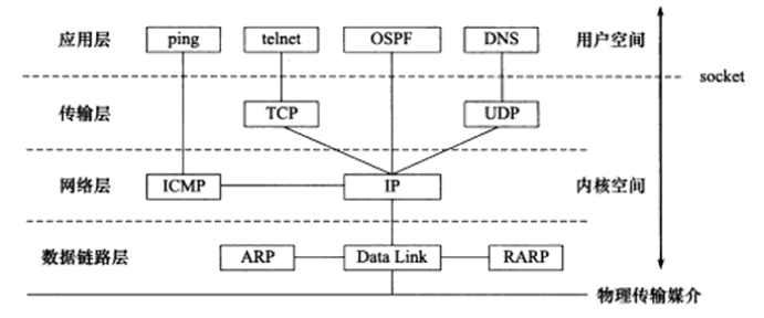
Figure 2 Encapsulation Process
2.1 TCP Segment
Data encapsulated by TCP is called a TCP segment, stored in kernel space, abbreviated as TCP segment. A TCP segment includes: TCP header information and TCP kernel buffers (including send and receive buffers).
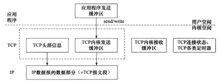
Figure 3 TCP Segment Encapsulation Process
Data Sending Process: When the sending application’s write function writes data to a TCP connection, the kernel’s TCP module first copies the data from the application’s send buffer to the corresponding TCP kernel send buffer, then the TCP module calls the IP module service to transmit the TCP segment to the network layer for further encapsulation as an IP datagram.
2.2 UDP Datagram
Data encapsulated by UDP is called a UDP datagram. The encapsulation process is similar to that of TCP segments. The difference: UDP does not need to save a copy for the application. Once the UDP datagram is successfully sent, the datagram in the UDP kernel buffer is discarded. If the application detects that the datagram was not correctly received by the receiving end and needs to resend it, it must copy the data from user space back to the UDP kernel send buffer.
2.3 IP Datagram
Data encapsulated by IP is called an IP datagram. An IP datagram includes header information and data sections, where the data section can be a TCP segment, UDP datagram, or ICMP message. Once the IP datagram is fully encapsulated, it is passed to the data link layer for further encapsulation.
2.4 Frame
Data encapsulated by the data link layer is called a frame. The frame type varies by transmission medium. For example: Ethernet frame, Token Ring frame.
2.5 Ethernet Frame
An Ethernet frame uses a 6-byte destination physical address and a 6-byte source physical address to represent the communication parties. The maximum transmission unit (MTU) of a frame indicates the maximum amount of upper-layer protocol data (such as IP datagram) it can carry, usually limited by the type of network. Ethernet frame MTU = 1500 bytes. Therefore, overly long IP datagrams may need to be fragmented for transmission.
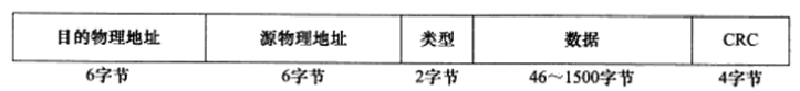
Figure 4 Ethernet Frame Structure
Frames are the byte sequences ultimately transmitted over the physical network. Thus, the encapsulation process is complete.
3. Demultiplexing
Demultiplexing is the reverse process of encapsulation. When a frame reaches the destination host, it is passed up the protocol stack from the bottom. Each layer protocol processes the header information of its corresponding layer in the frame and hands the processed data to the target application. Demultiplexing relies on the type field in the header information, with the standard document RFC 1700 defining all type fields identifying upper-layer protocols and their corresponding values.
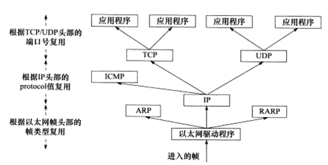
Figure 5 Ethernet Demultiplexing Process
The IP protocol, ARP protocol, and RARP protocol in the network layer all use the frame service provided by the data link layer to transmit data, thus a field is used in the data link layer’s frame header to distinguish them. In Ethernet, the link layer uses a 2-byte type field to indicate the upper layer (i.e., network layer) protocol. The values for the Ethernet frame type field received by the host are as follows:
-
0x800: Indicates that the data part of the frame is an IP datagram, and the Ethernet driver hands the frame to the IP module.
-
0x806: Indicates that the data part of the frame is an ARP request or response message, and the Ethernet driver hands the frame to the ARP module.
-
0x835: Indicates that the data part of the frame is a RARP request or response message, and the Ethernet driver hands the frame to the RARP module.
Similarly, the ICMP, TCP, and UDP protocols in the transport layer use the IP protocol, so the header of the network layer’s IP datagram uses a 2-byte protocol field to distinguish them.
TCP segments and UDP datagrams in the transport layer distinguish applications by the 16-bit port number field in the header. For example, the DNS protocol corresponds to port 53, and the HTTP protocol corresponds to port 80. All well-known application layer protocol port numbers can be found in the /etc/services file.
4. ARP Protocol Working Principle
The ARP protocol implements the conversion from network addresses to physical addresses. The working principle is as follows: A host broadcasts an ARP request on its network, which includes the network address of the target machine. Other hosts on the network will receive this request, but only the requested target machine will respond to this ARP request, including its physical address.
4.1 Ethernet ARP Request/Response Message
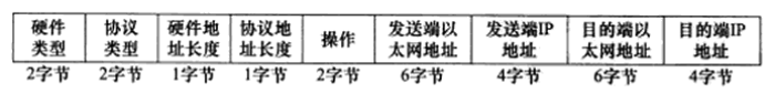
Figure 6 Ethernet ARP Request/Response Message Explanation:
-
Hardware Type: Defines the type of physical address, where 1 indicates a MAC address.
-
Protocol Type: Indicates the type of protocol address to be mapped, where 0x800 indicates an IP address.
-
Hardware Address Length: Measured in bytes, for MAC addresses, its length is 6.
-
Protocol Address Length: Measured in bytes, for IPv4 addresses, its length is 4.
-
Operation Field: Four operation types. 1=ARP request, 2=ARP response, 3=RARP request, 4=RARP response.
-
The last four fields specify the Ethernet addresses and IP addresses of the communicating parties. The sender fills in the other three fields except the destination Ethernet address to construct the ARP request. The receiving end fills in its own Ethernet address and exchanges the two destination addresses and the sender’s address while modifying the operation type (setting it to 2).
The length of the Ethernet ARP request/response message is 28 bytes, plus the 18 bytes for the Ethernet frame header and trailer (as shown in Figure 4), resulting in a total length of 46 bytes for an Ethernet frame carrying an ARP request/response message.
However, some implementations require the data portion of the Ethernet frame to be at least 46 bytes in length. In this case, the ARP request/response message will include some padding bytes to meet the requirement. Thus, the length of an Ethernet frame carrying an ARP request/response message is 64 bytes.
4.2 ARP Cache
ARP maintains a cache that stores the mapping of frequently accessed gateways or recently accessed machines’ IP addresses to physical addresses, avoiding duplicate ARP requests and improving packet sending speed.
Query command:
arp -aUsers can add or delete cache items in the ARP cache.
4.3 ARP Communication Process
Through remote login from 108 to 109, the ARP communication process is illustrated:
1) Clear the target address from the ARP cache (otherwise, ARP communication will not be executed)
sudo arp -d 192.168.1.1092) Use tcpdump to capture ARP packets.
sudo tcpdump -i eth0 -ent '(dst 192.168.1.109 and src 192.168.1.108) or (dst 192.168.1.108 and src 192.168.1.109)'3) Execute the telnet command on the test machine to remotely log in to the machine at 192.168.1.109.
telnet 192.168.1.109 echoOnce the telnet command is executed and a TCP connection is established between the two communicating hosts (with telnet outputting “Connected to 192.168.1.109”), press Ctrl+] to bring up the telnet command prompt, then input quit at the telnet command prompt to exit the telnet client program (since ARP communication is completed before the TCP connection is established, subsequent content does not need to be concerned). Among the many packets captured by tcpdump, only the first two are related to ARP communication. They are displayed as follows:
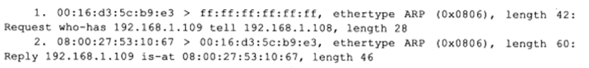
Figure 7 First Remote Login Ethernet Frame
The packets captured by tcpdump are essentially Ethernet frames, and various options of this command control the filtering (for example, using dst and src to specify the destination and source IP addresses of the communication) and display (for example, using the -e option to enable the display of Ethernet frame header information).
In the first packet, the source physical address of the ARP communication is 00:16:d3:5c:b9:e3, and the destination physical address is ff:ff:ff:ff:ff:ff, which is the Ethernet broadcast address, indicating the entire local area network. All machines on this local area network will receive and process such frames. The value 0x0806 is the type field value in the Ethernet frame header, indicating that the target of demultiplexing is the ARP module. This Ethernet frame has a length of 42 bytes (actually 46 bytes, as tcpdump counts the 4-byte CRC field at the end of the Ethernet frame), with the data portion length being 28 bytes. “Request” indicates this is an ARP request, and “who-has 192.168.1.109 tell 192.168.1.108” indicates that machine 108 is querying the IP address of machine 109.
In the second packet, the source physical address of the ARP communication is 08:00:27:53:10:67, and the destination physical address is 00:16:d3:5c:b9:e3. “Reply” indicates this is a response to a request, and “192.168.1.109 is at 08:00:27:53:10:67” indicates that the target machine 109 reports its physical address. This Ethernet frame has a length of 60 bytes (actually 64 bytes), indicating that it used padding bytes to meet the minimum frame length requirement.
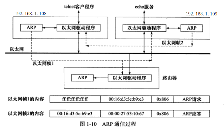
Figure 8 ARP Communication Process
5. DNS Working Principle
Through domain name query services, machine domain names are converted into IP addresses, with implementations including NIS (Network Information Service), DNS, and local static files.
5.1 DNS Query and Response Message
DNS is a distributed domain name service system. Each DNS server stores a large number of mappings between machine names and IP addresses, and is dynamically updated. Network client programs use the DNS protocol to query the IP address of the target host from the DNS server.
DNS Query and Response Message Format:
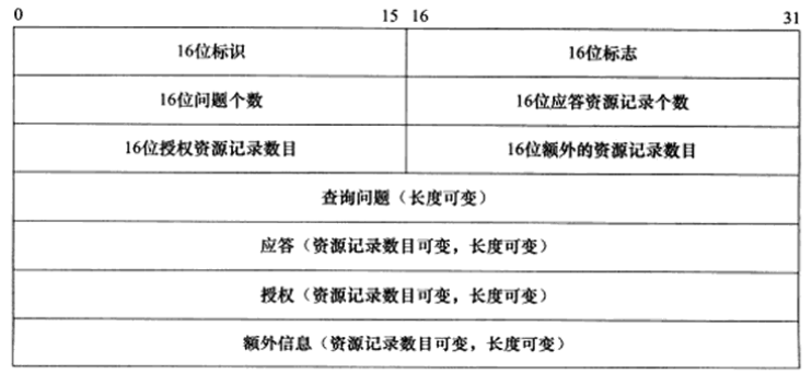
A 16-bit identifier field is used to mark a pair of DNS queries and responses, distinguishing which DNS response corresponds to which DNS query.
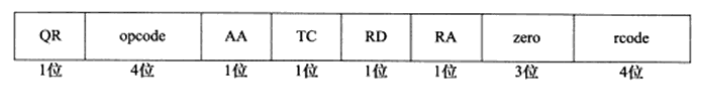
A 16-bit flag segment is used to negotiate specific communication methods and feedback communication status. The 16-bit flag segment in the DNS message header is shown below:
-
QR, Query/Response Flag. 0=Query Message, 1=Response Message.
-
Opcode, Defines the type of query and response. 0=Standard Query, 1=Inverse Query (obtaining host domain names from IP addresses), 2=Request Server Status.
-
AA, Authoritative Answer Flag, used only by response messages. 1=The domain name server is an authoritative server.
-
TC, Truncation Flag, used only when DNS messages use UDP services. Since UDP datagrams have a length limit, all overly long DNS messages will be truncated, with 1 indicating that the DNS message exceeds 512 bytes and has been truncated.
-
RD, Recursive Query Flag. 1=Perform recursive queries, meaning if the target DNS server cannot resolve a hostname, it will continue querying other DNS servers recursively until a result is obtained and returned to the client. 0=Perform iterative queries, meaning if the target DNS server cannot resolve a hostname, it will return the IP addresses of other DNS servers it knows to the client for reference.
-
RA, Recursion Available Flag. Used only by response messages, 1 indicates that the DNS server supports recursive queries.
-
Zero, These 3 bits are unused and must all be set to 0.
-
Rcode, 5-bit return code indicating response status. 0=No Error, 3=Domain Name Does Not Exist.
The next four fields indicate the number of resource records in the last four fields of the DNS message. For query messages, it generally contains one query, while the response resource record count, authoritative resource record count, and additional resource record count are all 0. The response message’s answer resource record count is at least 1, while the authoritative resource record count and additional resource record count can be 0 or non-zero.
The query question format is shown in the image below:
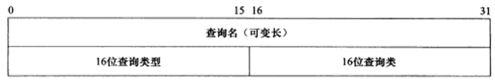
The query name is encapsulated in a specific format to query the host domain name. The 16-bit query type indicates how to perform the query operation, with common types including:
-
Type A, Value=1, indicates obtaining the target host’s IP address.
-
Type CNAME, Value=5, indicates obtaining the target host’s alias.
-
Type PTR, Value=12, indicates inverse queries.
The 16-bit query class is usually 1, indicating obtaining Internet addresses (IP addresses).
The response field, authoritative field, and additional information field all use the Resource Record (RR) format. The resource record format is shown in the image below:
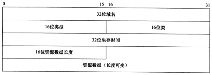
In the image, the 32-bit domain name is the name corresponding to the resource in this record, with a format identical to that of the query name field in the query question. The 16-bit type and 16-bit class fields also match the corresponding fields in the DNS query question.
A 32-bit time-to-live indicates how long the query record result can be cached by the local client program, measured in seconds.
The 16-bit resource data length field and the content of the resource data field depend on the type field. For Type A, the resource data is a 32-bit IPv4 address, and the resource data length is 4 bytes.
5.2 Accessing DNS Services on Linux
To access DNS services, one must know the IP address of the DNS server. Linux uses the /etc/resolv.conf file to store the IP addresses of DNS servers.
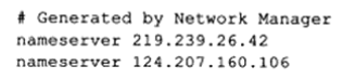
In this, the two IP addresses are the primary and secondary DNS server addresses.
The commonly used client program for accessing DNS servers on Linux is host. For example, the following command queries the IP address of machine www.baidu.com from the primary DNS server 219.239.26.42:
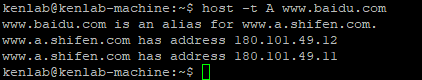
The output of the host command shows that the machine name www.baidu.com is an alias for www.a.shifen.com. This machine name corresponds to two IP addresses. The host command uses the DNS protocol to communicate with the DNS server, with the -t option indicating which type of query to use for the DNS protocol. Here, type A is used, which retrieves the IP address via the machine’s domain name.
5.3 Observing DNS Communication Process with tcpdump
By using the following command to capture Ethernet frames transmitted over the LAN.
sudo tcpdump -i enp2s0 -nt -s 500 port domain and host -t A www.baidu.comWhen using tcpdump to capture packets, the “port domain” filter is applied, indicating that only packets using domain services (i.e., DNS query and response messages) are captured. The tcpdump output is as follows:
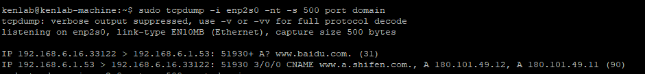
The two packets start with “IP,” indicating that the content following describes the IP datagram. Tcpdump describes one end of the communication in the form of “IP address.port number”: using “>” to indicate the direction of data transfer, with the source on the left and the destination on the right. Hence:
-
The first datagram is a DNS query message sent from the test machine (IP address: 192.168.6.16) to its primary DNS server (192.168.6.1) (the destination port 53 is used for DNS services), with the value 51930 being the DNS query message identifier, which also appears in the DNS response message. “+” indicates that the recursive query flag is enabled, “A?” indicates that type A query is being used, and “www.baidu.com” is the query name in the DNS query question. The number 31 in parentheses indicates the length of the DNS query message (in bytes);
-
The second datagram is the DNS response message from the server. In this packet, “3/0/0” indicates that this message contains 3 answer resource records, 0 authoritative resource records, and 0 additional information records. “CNAME www.a.shifen.com., A 180.101.49.12, A 180.101.49.11” indicates the content of the three answer resource records. Here, CNAME indicates that the following record is the machine’s alias, and A indicates that the following record is the IP address. The length of the response message is 90 bytes.
Note:
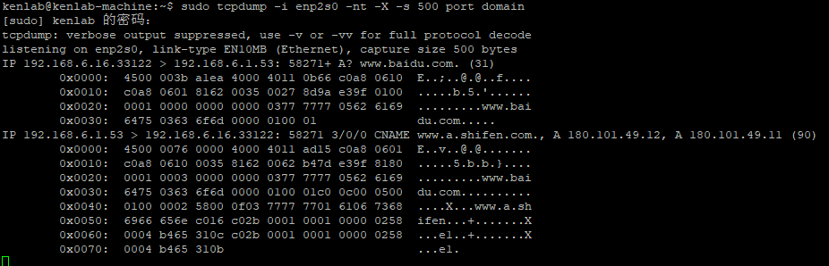
By enabling the tcpdump -X option, one can see each byte of the DNS message, thus understanding the specific meaning of the above 31-byte query message and 90-byte response message, as shown in the image below:
5.4 Relationship Between Sockets and TCP/IP Protocol Suite
Since the data link layer, network layer, and transport layer protocols are implemented in the kernel, the operating system needs to provide a set of system calls that allow applications to access the services provided by these protocols. There are two main APIs (Application Programming Interface) that implement this set of system calls: socket and XTI, with XTI having been largely deprecated.
The API defined by sockets provides the following two functionalities: first, it allows application data to be copied from the user buffer to the TCP/UDP kernel send buffer for transmission (e.g., the send function), or from the kernel TCP/UDP receive buffer to the user buffer for reading data; second, it allows applications to modify certain header information or other data structures of the protocols in the kernel, thus finely controlling the underlying communication behavior. For example, the setsockopt function can be used to set the time-to-live of IP datagrams on the network.
Additionally, sockets provide a universal network programming interface, allowing access not only to the TCP/IP protocol stack in the kernel but also to other network protocol stacks (such as the X.25 protocol stack, UNIX local protocol stack, etc.).
Link: https://www.cnblogs.com/zhongqifeng/p/14555474.html
(Copyright belongs to the original author, infringement will be deleted)