
Project Name: Computer Status Display Instrument Based on STM32
Author: freeak_miku
Introduction
The main event, the main event, absolutely the main event!
Just looking at the cover of this compilation does not reveal much, but after clicking into the Bilibili video, everything becomes clear, and one can’t help but shout “6666~”.
The inspiration for this project comes from the video of Bilibili UP master @日出东水Studio. (This compilation also recommends everyone to take a look, as it has a high view count)
Project Introduction
The project uses AIDA64extreme as the host computer and adopts the STM32F103C8T6 core board as the controller, with the project program rewritten based on Arduino.
Improvements
1. Use AIDA64extreme as the host software, which can obtain more parameter information including CPU, memory, GPU, battery voltage, hard disk usage rate, etc. The program can be modified for DIY, creating more possibilities.
2. Use serial communication to connect to the computer via USB, allowing usage on desktop computers without Wi-Fi cards.
3. The STM32F103C8T6 core board is used as the controller.
-
Due to differences in the output voltage of each computer’s USB port, not all are standard 5V outputs, which may affect output accuracy when using PWM to simulate DAC output. Therefore, Arduino NANO or UNO based on 5V microcontrollers were not chosen as controllers. (Of course, it is also possible to provide a stable reference voltage to NANO or UNO externally, but it is relatively troublesome). The STM32F103C8T6 core board has a built-in 3.3V voltage regulator chip, which can ensure that the DAC output is relatively accurate and not affected by the computer’s USB voltage.
-
Due to the rising price of the ATmega328P microcontroller, the domestic Arduino NANO price has approached 30 yuan, while the STM32F103C8T6 core board price remains around 20, making it more economical.
4. The program is written using Arduino IDE, without complex register configurations, making it easy to modify. (Actually, the author is not good at using Keil and CubeMX  )
)
5. Supports program calibration and fine-tuning of the voltmeter to improve adaptability.
Required Tools
-
Soldering iron
-
DuPont wires
-
Any USB serial downloader, recommended CH340
-
Micro USB data cable
Required Components
-
One STM32F103C8T6 core board
-
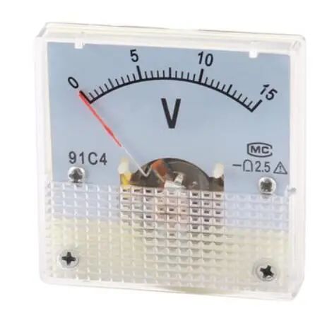
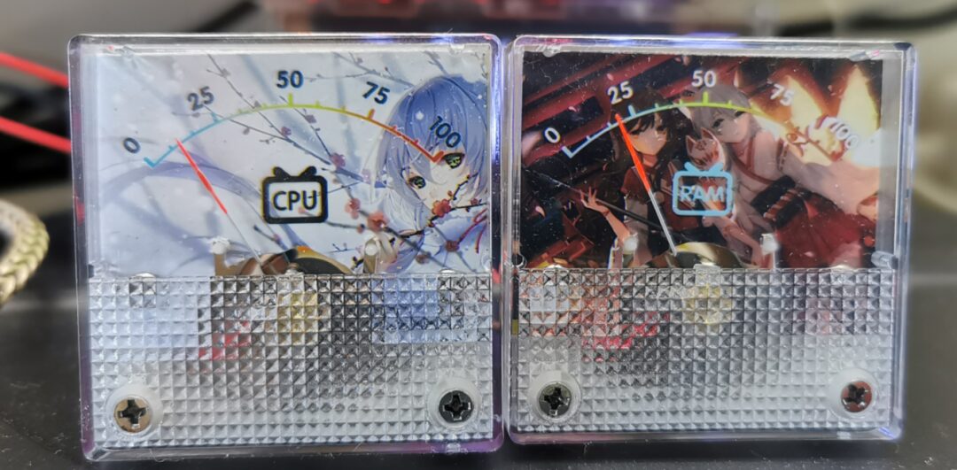
Two 91C4 voltage meters (need to purchase the 3V range version)
Production Process
1. Set up the Arduino development environment for STM32
Notes:
-
When flashing the bootloader, the core board needs to have boot0 connected to position 1 and boot1 connected to position 0; after successful flashing, it needs to be restored to both connected to position 0.
-
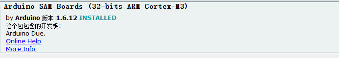
After installing the Arduino_STM32 package and drivers, you need to additionally install support for Arduino SAM Boards in the Arduino board manager.
-
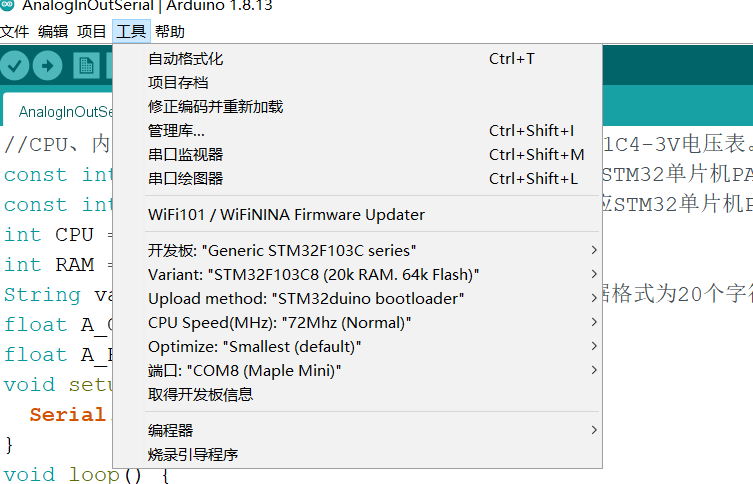
The program download must select the microcontroller model and serial port as follows (Once the driver is successfully installed and the development board is connected to the computer via the onboard micro USB, the maple mini serial port can be recognized)
2. Flash the program
Open the “CPURAMGET.ino” in the “program” folder of the project attachment and download the program according to the instructions in point one.
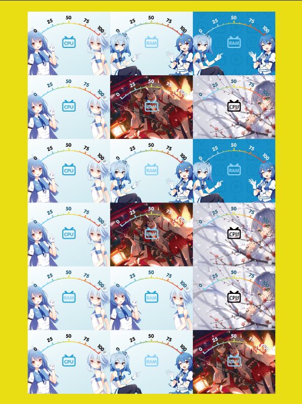
3. Create the dial
-
You can use the original author’s PHOTOSHOP file to replace the background and create your favorite dial.
-
Friends without a color printer can also print using a black-and-white printer (If the printed image is too light, you can adjust the contrast and brightness)
-
If you don’t have a color printer but want to make a colored dial, it is recommended to search for “photo printing” services on Taobao (The 8-inch (6R, 15.2*20.3cm) printing with free shipping costs around 2 yuan, which is quite economical)
4. Cut and make the dial
Disassemble the 91C4 voltage meter and take out the original metal dial. Cut the printed dial image according to the shape of the dial using scissors, and paste the cut dial image onto the surface of the original metal dial using glue. Reassemble the voltage meter and adjust the installation position to ensure the pointer aligns with the zero point and the dial does not interfere with the pointer’s movement.
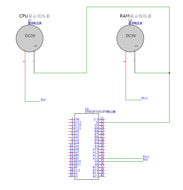
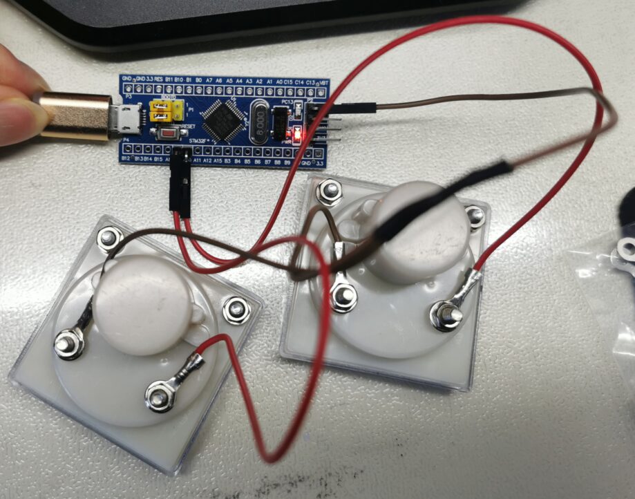
5. According to the connection diagram, connect the PA9 and PA10 pins of the STM32 core board to the positive terminals of the voltage meters displaying CPU usage and memory usage. The negative terminals of the two voltage meters should be connected in parallel to the core board GND.
6. Download AIDA64extreme software and make the following settings:
(1) Connect the STM32 core board to the computer via MICRO USB, and confirm the connected serial port number through Arduino IDE.

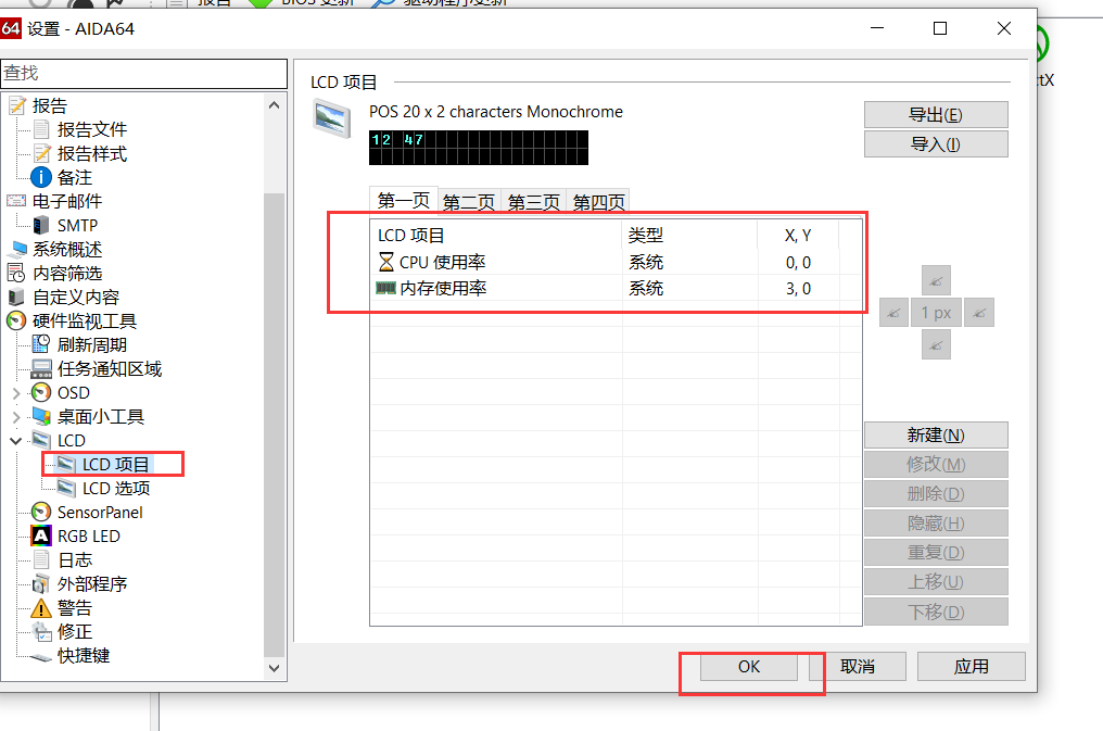
(2) Open AIDA64extreme software, click on “File” – “Settings”
(3) Select LCD, and choose POS as the screen type.

(4) Click on the left “LCD Project”, and set the screen output parameters according to the parameters below, or import the configuration file provided in the project file.
(5) Check whether the position of the voltage meter pointer matches the memory and CPU usage of the computer.
Micro adjustments can be made through “Voltage Meter Range” and “Power Voltage” in the program, where 3.30v is the voltage measured by a multimeter at the STM32 core board 3.3v output pin.

(6) Use the 3D model from the original author on Bilibili to 3D print the shell, or use KT board or acrylic board to make the shell yourself.
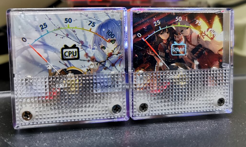
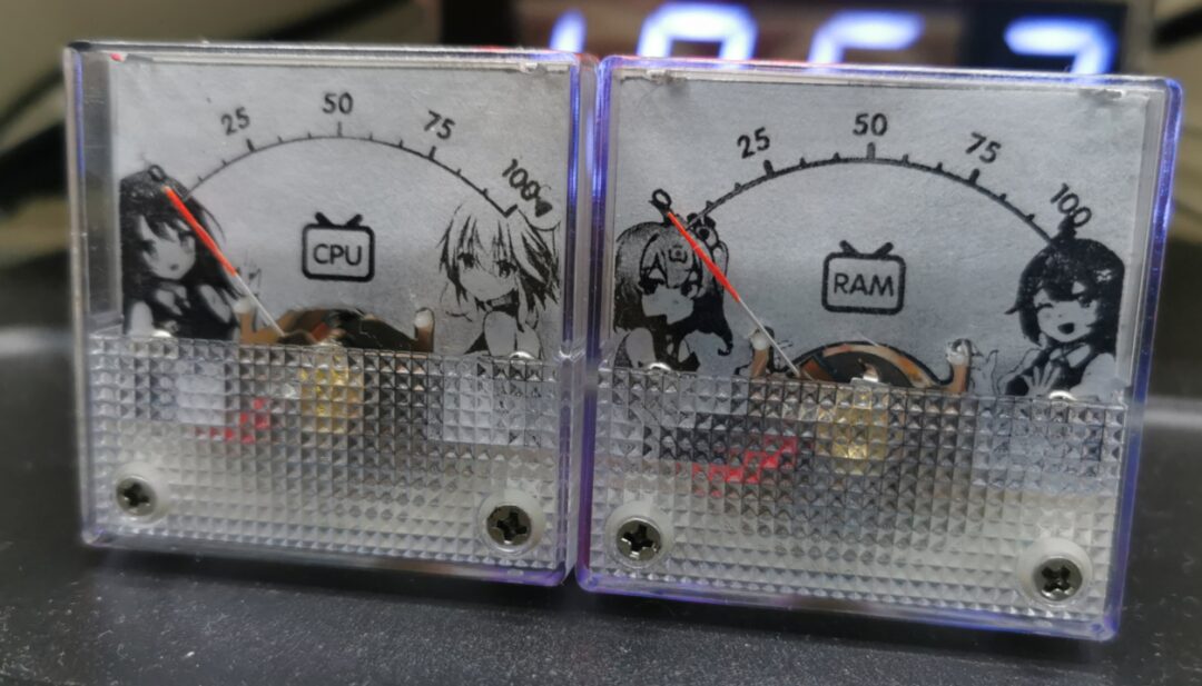
Finished product effect picture
Circuit Design Appreciation
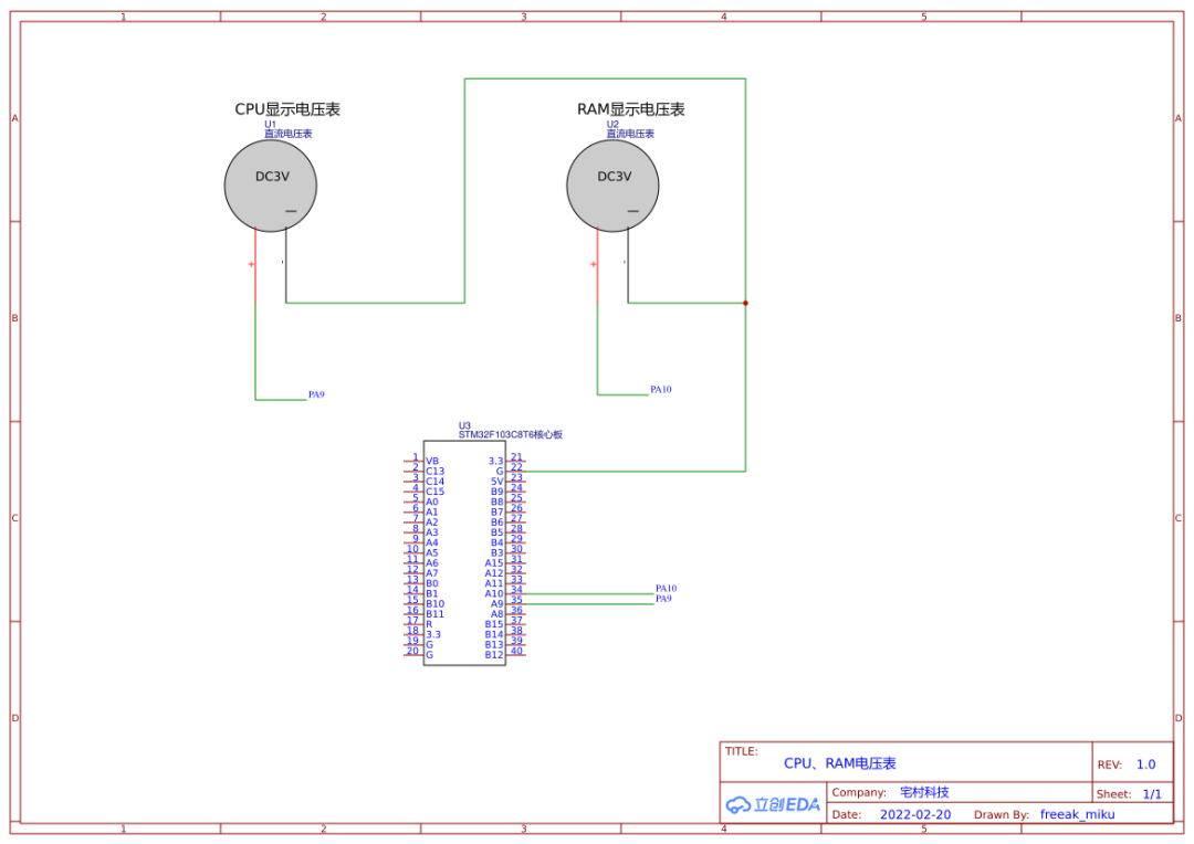
Schematic Diagram
Related project attachments can be viewed in the original project download.
If there are any other questions, you can leave a message to the author at the bottom of the original project.
Please click “Read the original text” to view the original project
Those who can persist until the end are either big shots or genuinely love this compilation. Knowing that at the end of this compilation, everyone will come to a closing statement.
There’s nothing much to say today, the weather is warming up, the sun is out, and downstairs there is a long queue for nucleic acid testing.  The afternoon sun shines on me, and I feel calm inside.
May the world be at peace~

Previous Open Source Recommendations
Ice Dun Dun
 The Winter Olympics Appointment – The Snow Rongrong is on its way
丨More
Graduation Project
Smart Epidemic Prevention Access Control Based on STM32
丨More
DIY Creative
Bluetooth QCC303X Bluetooth Receiver
丨More
Power Supply
SC8701 Automatic Boost and Buck Car Charger
丨More
Internet of Things
Who wants to make a smart curtain? Quickly grab it

Follow me
Aiming to make you an excellent hardware engineer!

Share

Collect

Like

Watch