
What is MultiWii?MultiWii is a universal remote-controlled multi-rotor flight control software developed using Arduino platform technology. Initially, it was designed to support the gyroscope and accelerometer of the Nintendo Wii controller, which can be found in the accessories of the Nintendo WiiMote controller.By integrating sensors such as accelerometers, gyroscopes, barometers, magnetometers, and GPS, MultiWii can control more than 10 types of multi-rotor aircraft, including tri-copters, quadcopters, and hexacopters. The entire electrical part of the aircraft uses commercially available standard modules, and all components can be purchased online. By simply connecting the modules, you can build a mini quadcopter controlled via Bluetooth from a mobile phone.Hardware ListName
| Quantity |
Reference Price |
| Arduino Pro mini Module (ATMEGA328P5V 16MHz) |
1 |
11.8 |
| GY 521 3-axis accelerometer module |
1 |
9.2 |
| HC06 Bluetooth module (slave) |
1 |
17 |
| SI 2302 (N-MOS tube) |
4 |
0.11 |
| 10k Ω resistor (SMD) |
4 |
| 720 (or 716) motor |
4 |
2.8 |
| 55mm (or 44mm) clockwise propeller |
2 |
0.9 |
| 55mm (or 44mm) counter-clockwise propeller |
2 |
13.9 |
| 350mAh lithium battery for models |
1 |
0.1 |
| Small switch |
1 |
| Perfboard or copper-clad board |
| AWG26# silicone wire |
Small amount |
| AWG30# silicone wire |
Small amount |
| Foam board frame |
1 |
| USB-TTL programming cable |
1 |
2.5 |
| Lithium-ion battery charging module (TP40561A) |
1 |
2.5 |
Once you have all the components from the list ready, you can start working!1. Set Up Software EnvironmentIt is recommended to use Windows operating system, and the mobile phone used for remote control needs Android 4.0 or above.The Arduino IDE is the development tool for Arduino, used to write Arduino programs and upload them to the Arduino development board for execution. The latest version of Arduino IDE can be downloaded from https://www.arduino.cc/, just choose the version for your operating system. The Windows version of the IDE can be either an installer or a portable version. During the production process, the debugging software MultiWii Conf is needed, and you will need to configure the JAVA environment. The latest version of JAVA can be downloaded from http://www.java.com, by clicking on the “Free JAVA Download” in the middle of the homepage, which will directly redirect you to the JAVA download page suitable for your computer’s operating system. Download and install it.In this project, we use MultiWii version 2.2, which can be used for dozens of flight control boards, sensors, etc. To adapt it to our mini quadrotor, some settings in the software need to be modified. After downloading MultiWii 2.2, open MultiWii.ino in the Arduino IDE. The IDE window will show tabs like “Alarms”, “EPPROM”, etc., which are all necessary for the flight control program, and will be compiled and uploaded to the Arduino Pro mini’s flight control program. The settings we modify are in Config.h. Open the Config.h tab and make the modifications in order as follows. You can use the “Find” command, which generally involves commenting or uncommenting related programs, i.e., adding “//” or removing “//”.MultiWii EZ-GUI is the MultiWii flight control configuration program’s APP for Android, which can wirelessly connect to MultiWii flight control via Bluetooth for parameter monitoring and settings. The APP has a simple Bluetooth control flight interface for remote-controlled flying.2. Assemble the AircraftThe frame of this quadcopter is made from foam board, which is a foamed PVC board with a low density, commonly used in making advertisement signs, and can be bought at advertising stores. My frame is shown in the diagram, with a simple design. The ends of the cross are slotted to facilitate motor installation, and you can cut it yourself with a blade or ask an advertising store to help you cut it.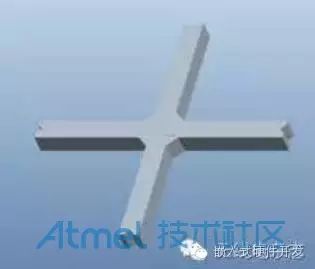 Frame DiagramMotor installation can use hot melt glue or other adhesives. Since the motors generate a lot of heat during operation, which may soften the hot melt glue, it is advisable to use a fiber tape to assist in fixing when using hot melt glue. When installing, try to keep the axis perpendicular to the frame plane. The rotation directions of the four propellers of the aircraft are specified and must be strictly followed during installation to ensure the correct installation of clockwise and counter-clockwise propellers. The arrows in the diagram indicate the front of the quadcopter. The rotation directions of the motors on the left and right sides are opposite, with diagonal propellers being clockwise and counter-clockwise respectively. 3, 9, 10, and 11 are the PWM output port numbers of the Arduino Pro mini. Motors 3 and 9 are installed with clockwise propellers, blowing air downward when rotating clockwise, with the back of the propeller marked “A”. Motors 10 and 11 are installed with counter-clockwise propellers, blowing air downward when rotating counter-clockwise, with the back of the propeller marked “B”. Drill 4 holes at the bottom of the four arms of the frame and insert 4 hard cotton swabs as a simple landing gear.
 Propeller Installation Top ViewAfter completing the structure, it’s time to connect the circuits of the various modules. The motor control board uses MOSFETs to simulate electronic speed control. This circuit can be soldered using a perfboard. I made a small circuit board myself, and due to the use of SMD resistors, the size is very small. The wiring diagram can be referenced in the following image.
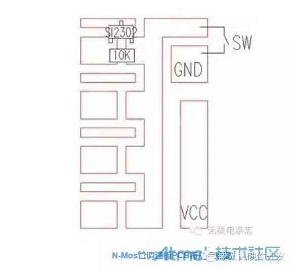
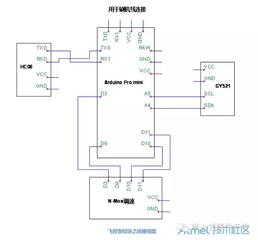
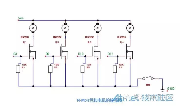
 3. Overall DebuggingDo not connect the battery to the quadcopter at first. Connect the Arduino Pro mini to the computer using the programming cable. Open MultiWii Conf, click connect, and read the data. Tilt the quadcopter to see the curves below start to change. Place the quadcopter level and still, click the calibrate accelerometer button to calibrate the attitude position. Once the curves stabilize, click to write to the flight control, as shown in the debugging program interface. After the program adjustments are complete, close data reading, disconnect, close the program, and disconnect the programming cable.
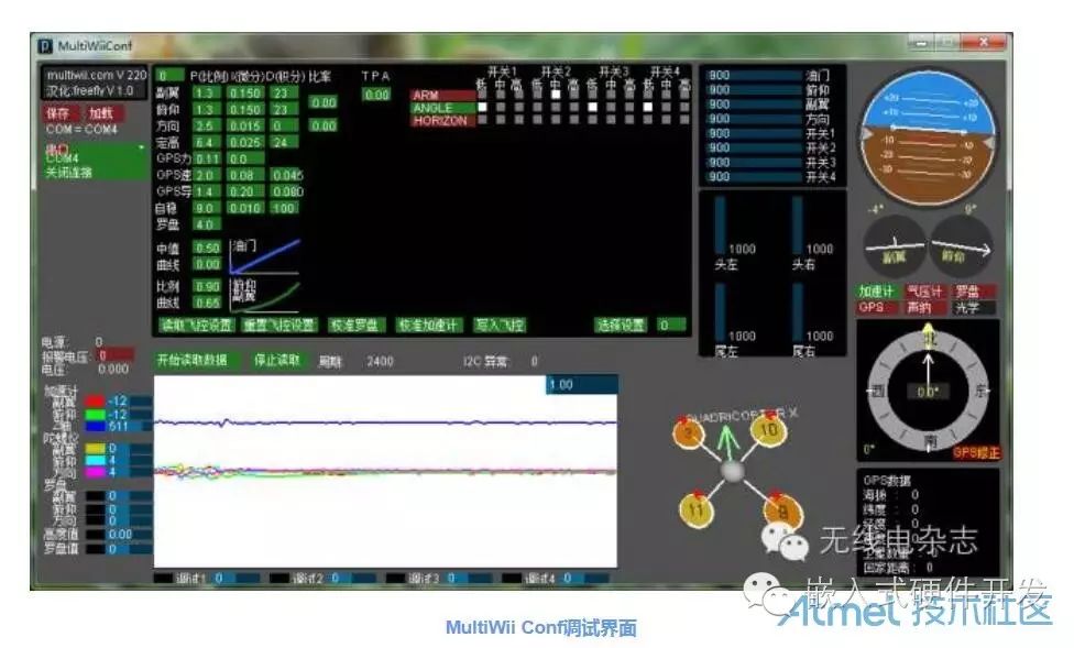 Next, start trying to connect the phone. Run MultiWii EZ-GUI on the phone. Before using it for the first time, you need to set it up. Swipe left to the “Settings” page, click the “Settings” button, and adjust the parameters as needed. The Bluetooth settings on the first page need to select the Bluetooth name of the quadcopter, while other settings are default values. After completing all settings, the application will restart, and click “Confirm”.
 Bluetooth Control Interface
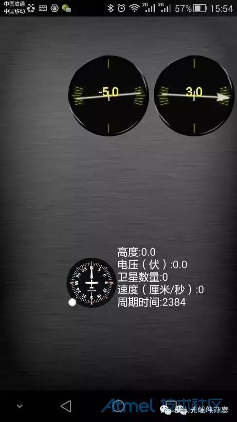 Dashboard InterfaceWhen starting the test flight, you may encounter various issues, such as unstable attitudes or drifting in one direction. If there are problems during the test flight, check aspects like the motor axis consistency and attitude sensors. For example, if the motor axes are all tilted in one direction, the quadcopter will rotate in that direction during flight; if the flight control starts self-check with the body tilted, it may cause sensor confusion, leading to significant tilt outputs when the body is level, causing it to always tilt in one direction or even flip during flight. Only through careful and serious debugging and patient test flights can this mini quadcopter allow you to experience the joy of flying.Final ThoughtsThe total cost of the quadcopter is about 80 yuan, and simpler ready-made quadcopters can also be purchased on certain platforms. However, the spirit of DIY is—”It’s all about the tinkering!” During the making process, I encountered various difficulties such as disconnections of the Bluetooth board’s wiring from the PCB copper traces, inexplicably burnt Arduino Pro mini, burnt 16 MOSFETs, etc. This is all part of the tinkering. But through self-learning, searching for information online, and discussions, I finally saw this small and simple quadcopter wobbling into the air. More importantly, the things learned in the process make all the previous tinkering worthwhile.