The low-altitude economy is booming, and the EVTOL trend is rising. The flight control system is the core system of the aircraft, and it involves transition phases that are not present in general aircraft, posing greater safety challenges. Based on this, we take the development of fully autonomous control laws for vertical take-off and landing aircraft as a case study to briefly introduce the process and steps of system development, as well as the tools and methods used, and finally demonstrate through flight tests. We welcome readers who are interested to communicate with each other, and if there are any errors, please feel free to point them out.
This article is the third in the VTOL aircraft series launched by Zhengyao Flight Control (to view the previous two articles, click here). The content primarily revolves around the integrated verification process of vertical take-off and landing aircraft (Vertical Taking Off and Landing, VTOL).
01
Integrated Verification
Depending on the different system aspects involved in the simulation, simulation methods are typically classified as follows:
Model in the Loop Simulation (MIL). The control model’s output control quantities are used as inputs to the aircraft’s mathematical model, while the measurable physical quantities output from the aircraft model serve as inputs to the control model, forming a closed-loop system for task-level simulation testing.
Software in the Loop Simulation (SIL). The control algorithm model is automatically generated into C language code using the Simulink Coder/Embedded Coder tools provided by Simulink, and then the consistency of the algorithm model and the algorithm code’s execution results is checked.
Processor in the Loop Simulation (PIL). Based on SIL, the C language code is further cross-compiled into firmware that can run on flight control hardware and burned into the hardware. Communication is established between the host computer and the hardware, testing stimuli are generated through Simulink signal sources, and the results of the firmware calculations are returned to Simulink for centralized processing, checking the consistency of the algorithm model and firmware execution results.
Hardware in the Loop Simulation (HIL). The control quantities output from the firmware in the flight control hardware are used as inputs to the aircraft’s mathematical model, while measurable physical quantities output from the aircraft model replace the sensor inputs of the flight control hardware, forming a semi-physical closed-loop system for simulation testing. To improve the realism of the simulation while reducing the risks and costs of actual flight tests, it is usually considered to include physical components such as sensors, servos, and motors in the closed-loop simulation to ensure that the dynamics, physical limitations, noise, and random errors of the hardware itself are evaluated and confirmed before actual flight tests.
02
MIL Simulation
(1) Establishing the Aircraft Mathematical Model
The mathematical model of the aircraft is usually established at the beginning of the control law design. Designers need to use the trim linearization method to simplify the nonlinear six-degree-of-freedom dynamic model into a four-order or second-order linear small disturbance model that is decoupled in lateral and longitudinal directions, represented in the form of system transfer functions or state-space equations. Then, classical control theory or modern control theory methods are used to analyze system characteristics and design control laws and parameters. Finally, during the functional verification stage, the control performance is validated through time-domain responses of nonlinear simulations to see if they meet design requirements.
An accurate aircraft model can greatly ensure the degree of conformity between the control law design performance and the actual control performance. However, uncertainties in the model such as accurate aerodynamic data, control surface and engine dynamic characteristics, sensor measurement errors, and manufacturing errors in the airframe hinder the acquisition of precise models. Overcoming these obstacles requires significant financial and time investments. To address this issue, engineering practices typically employ various assumptions and approximate estimation methods, such as using rigid body assumptions to eliminate the effects of elastic deformations in the dynamic equations, replacing wind tunnel data with CFD results, and simulating actuator dynamic characteristics with typical first-order or second-order systems with pure delays. For more detailed formula derivations and principles of flight dynamics, it is recommended to read relevant professional books and literature for in-depth understanding.
The mathematical model of the tilt-rotor aircraft established in this case can exhibit the rigid body dynamics and kinematic characteristics of the aircraft. The aerodynamic model can describe the normal aerodynamic characteristics of the aircraft and the stall phenomenon at high angles of attack. The power model supports simulating the rotor tilt process and the gyroscopic effect caused by the rotation of components, while the landing gear model supports simulating ground take-off and landing tasks. The servo, motor, and sensor models can simulate the common characteristics of actual components.
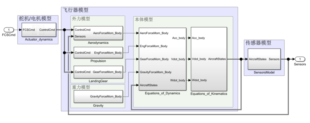
Aircraft Model
In addition to the aircraft model and flight control model, we can also add some modules provided by Simulink to enrich the functionality of the simulation model. For example, we can add a joystick input module to manually generate control input commands.
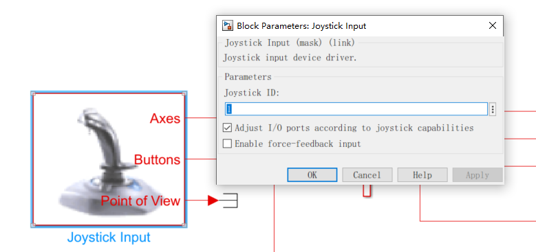
Joystick Input Module
The state data of the aircraft can be sent to the FlightGear open-source flight simulation software via the FlightGear interface module to generate virtual simulation views.
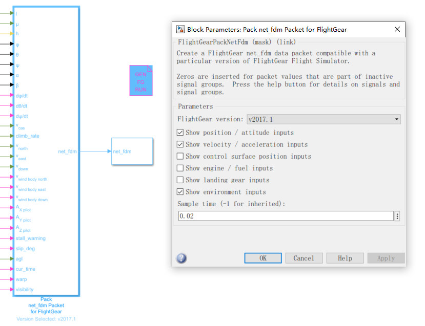
FlightGear Interface Module
A dashboard module can also be added to simulate a ground station for data monitoring and task command sending.
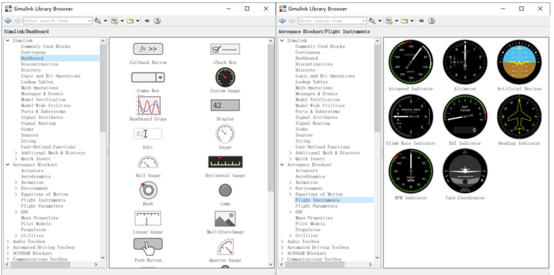
Dashboard Module Library
Finally, we obtained a complete simulation model.
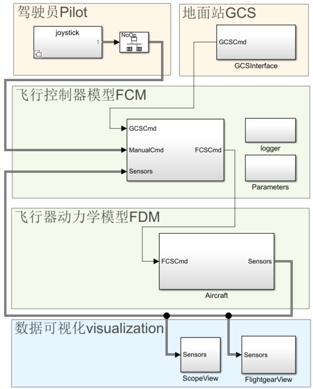
Simulation Model
(2) Quasi-Real-Time Simulation Settings
When running simulations, it is recommended to set Simulation Pacing for quasi-real-time simulation, meaning that the speed at which simulation time increases is consistent with actual time, thus ensuring that the real-time changes in simulation data and the movements of the aircraft in the virtual view are more realistic.
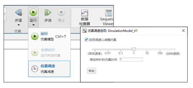
Quasi-Real-Time Simulation
(3) Running the Simulation
This section also takes the verification of the tilt transition control strategy as an example.
The task flow is as follows: The aircraft is initially on the ground, and after the ground station issues the take-off command, the aircraft automatically takes off, ascends vertically to the preset take-off height, and then automatically begins to transition to fixed-wing mode. After the transition is complete, it maintains level flight. A short time later, the ground station issues a landing command, and the aircraft begins to transition to multi-rotor mode, landing automatically until it touches down.
During the simulation process, the movements of the aircraft are monitored through the virtual view in the FlightGear software.
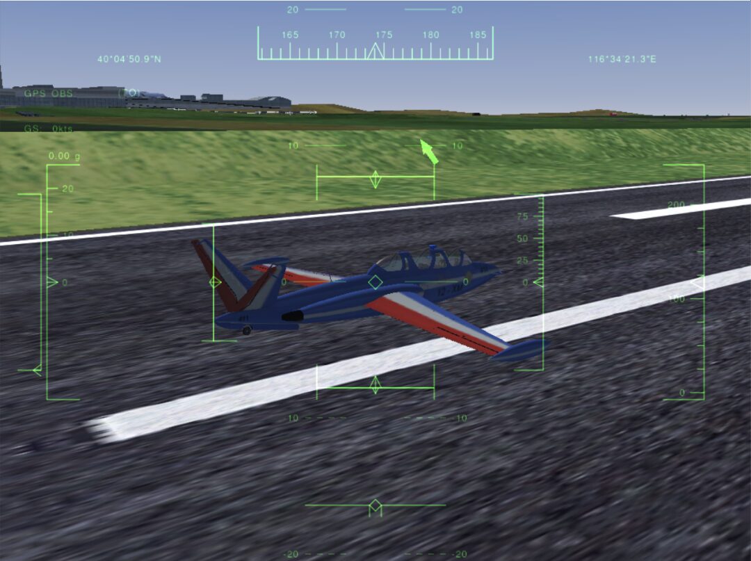
The aircraft waiting for take-off on the ground
After the simulation ends, open the Simulation Data Inspector to view the recorded signal curves and analyze the simulation results.
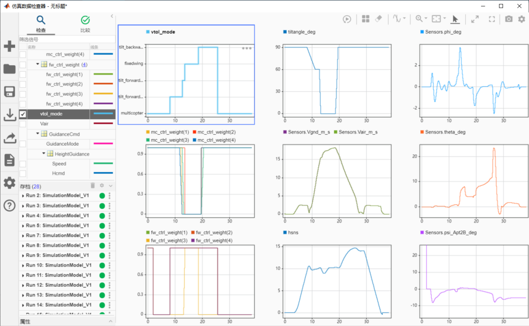
Viewing Simulation Results
During the transition to fixed-wing mode, the height decreased from 10m to a minimum of 8.9m, while the speed increased steadily from 0m/s at an acceleration of about 4m/s², with the entire transition taking about 5.4s. During the transition to multi-rotor mode, the height increased from 10m to a maximum of 14.7m, while the speed decreased steadily from 18m/s at an acceleration of about -2.3m/s², with the entire transition taking about 7s. The simulation results indicate that the current tilt transition control strategy meets the requirements for safe and stable transitions.
03
SIL Simulation
(1) Automatic Generation of C Language Code
First, open the model configuration interface, and in the validation of code generation, set the advanced parameters to create the module as SIL.
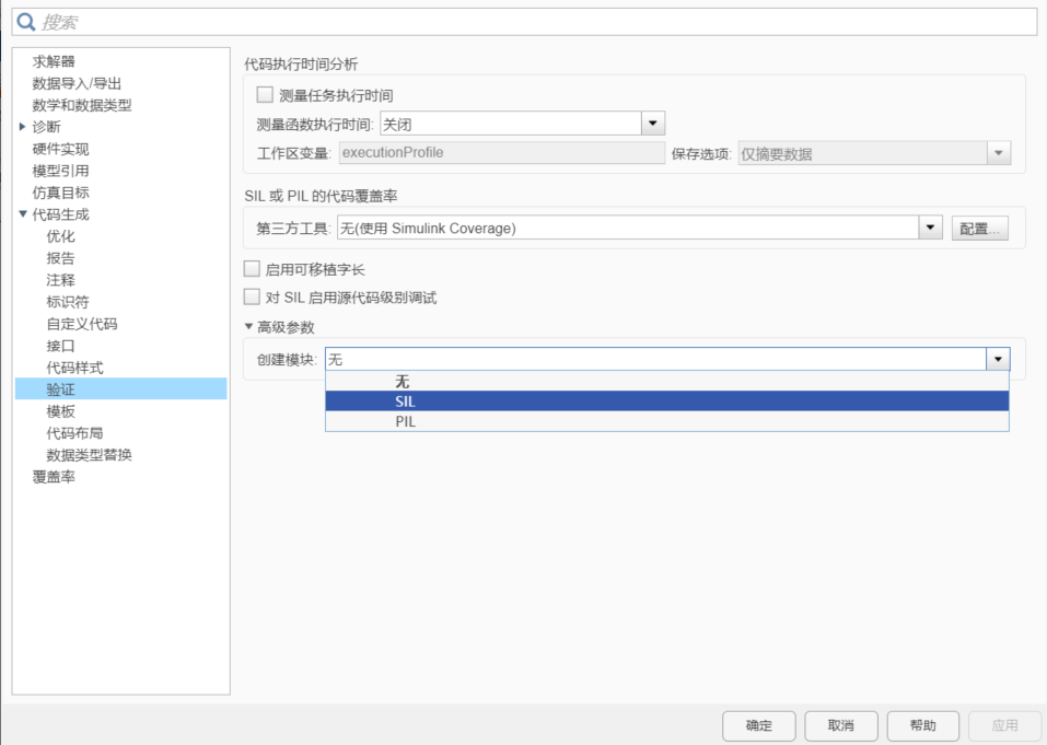
Configuring Model Parameters
Then return to the model, right-click on the flight controller model, select C/C++ code, and choose to compile this subsystem.
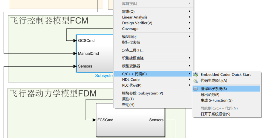
Compiling the Subsystem Module into C Code
After the compilation is complete, a packaging module for SIL simulation will appear. Entering this packaging module reveals that it is actually an S-Function module that calls the C code.
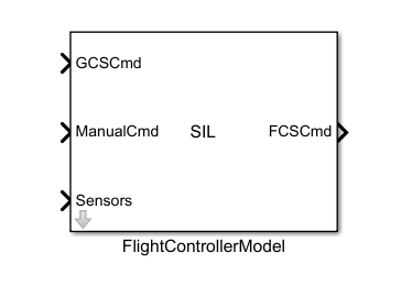
Automatically Generated SIL Simulation Module
Return to the top-level model and replace the original subsystem module with the automatically generated SIL module, and you can start SIL simulation testing.
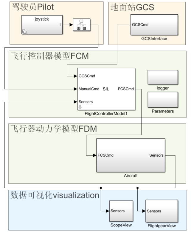
Top-Level Model After Adding SIL Module
SIL simulation is an equivalence test, so we need to set exactly the same simulation inputs, and then run the original simulation model and the simulation model with the replaced SIL module in succession. Finally, we compare the signal curves from both simulations in the data inspector. It can be seen that the signal curves from both simulations completely overlap, indicating that the output of the C code is completely consistent with the output of the control model simulation.
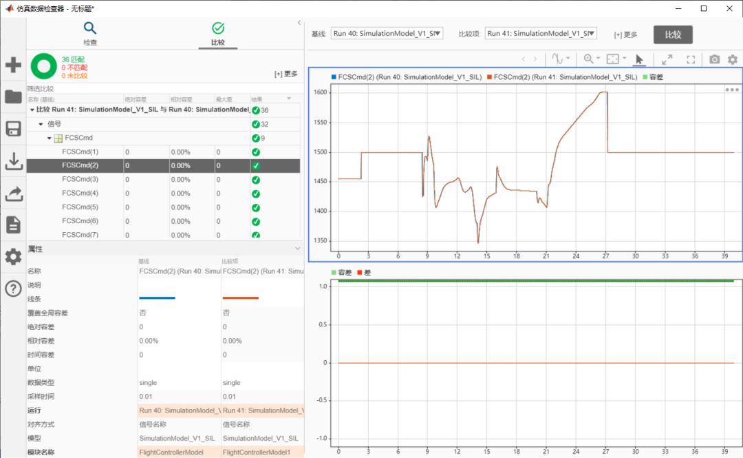
Checking the Consistency of Two Simulation Results
04
PIL Simulation
(1) Configuring the Target Hardware Support Package
Taking the Zhengyao Flight Control Obsidian A3 flight control as an example, the flight control processor is ARM Cortex-M7. Simulink provides a support package for ARM Cortex-M series processors, which can be found in the additional features resource manager under “Embedded Coder Support Package for ARM Cortex-M Processors”, and then installed according to the prompts.
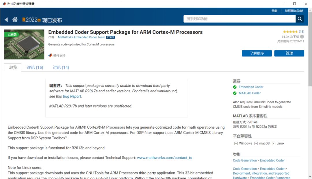
Hardware Support Package for ARM Cortex-M Series Processors
(2) Configuring the QEMU Emulator
PIL simulation in Simulink can run without connecting to actual hardware, but instead deploy the firmware code to run in the QEMU emulator. This method is equivalent to running PIL simulation on hardware while being easier to operate. First, find “Embedded Coder Interface to QEMU Emulator” in the additional features resource manager and install it.
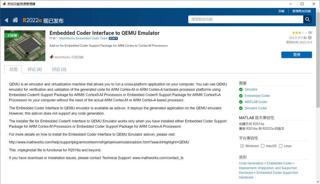
Installing Embedded Coder Interface to QEMU Emulator
After the installation is complete, follow the setup guide to complete the download and installation of QEMU Emulator version 2.5.0.
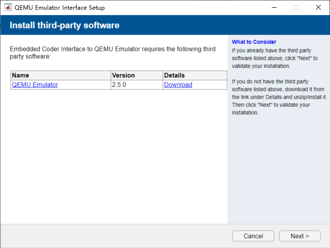
Downloading and Installing QEMU Emulator
(3) Automatic Generation of Test Firmware
Open the model configuration interface, select the target hardware as ARM Cortex-M3 (QEMU) in the hardware implementation.
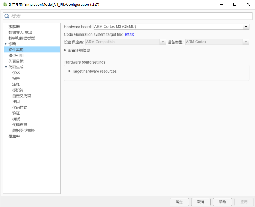
Setting Target Hardware
Then, like SIL simulation, set the advanced parameters for creating the module as PIL in the code generation validation options.
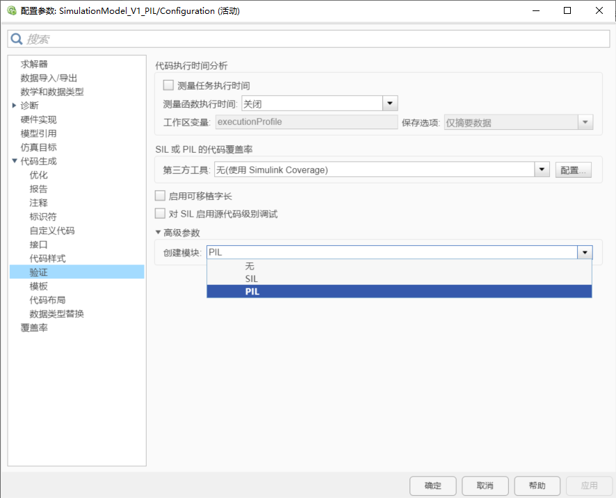
Configuring Model Parameters
Return to the top-level model, right-click on the subsystem module, and select C/C++ code to deploy this subsystem to hardware. Ultimately, we obtain a complete simulation model.
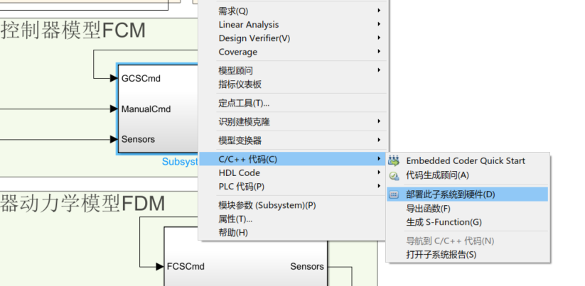
Cross-Compiling the Subsystem Module into Firmware Code
After the compilation is complete, the PIL simulation module corresponding to the controller model can be obtained.
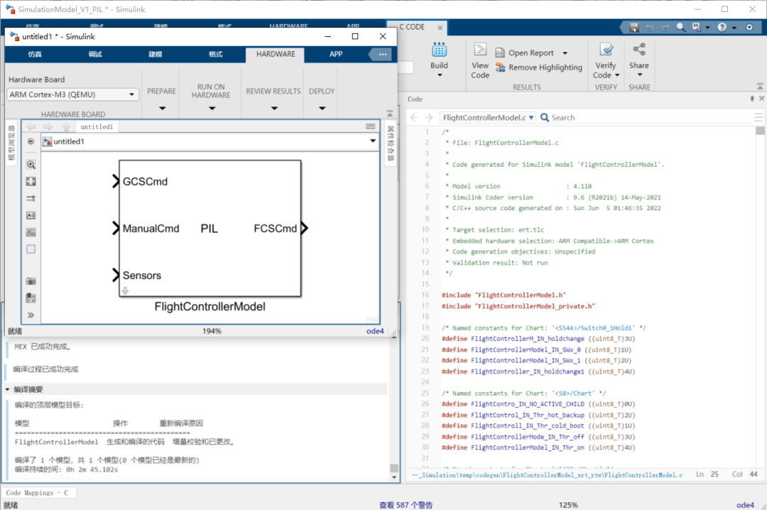
Automatically Generated PIL Module
The subsequent process is the same as SIL simulation; replace the original controller model with the PIL module, then run the simulation and check the consistency of the module output with the controller model simulation output.
05
HIL Simulation
The complete HIL simulation process typically requires the collaborative operation of devices such as flight control, ground station host, simulation machine, data link fusion station, aircraft actuators, and three-axis turntable to achieve task-level joint debugging and testing of flight control software and hardware, communication data links, ground station software, actuator dynamic characteristics, and sensor characteristics.
Zhengyao Flight Control products not only support a standard and complete HIL simulation process but also provide a simplified HIL mode: deploying the flight control code and aircraft model code separately on a master and a slave MCU. When the flight control runs in HIL mode, the outputs from the flight control are sent to the aircraft model, while the required sensor data for flight control is calculated in real-time by the aircraft model. This simplified HIL process facilitates efficient testing of flight control software logic, hardware computation performance, communication links, and ground station software, thereby confirming and eliminating systemic risks that could only be discovered during actual flight tests in the laboratory in advance.
06
Flight Test Verification
After the above design verification process and iterative improvement of the controller model, flight test verification of all control system functions can begin. The complete flight test video can be viewed on the Zhengyao Flight Control official website.

Validation aircraft used in flight tests
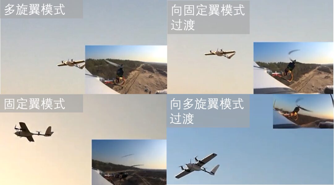
Screenshot from the flight test video
For more detailed content about VTOL aircraft, you can click to read the original article published by Zhengyao Flight Control on the WeChat public account.
/END/


Long press to view
Official Website

Long press to follow
Bilibili

Long press to join
Fan QQ Group