1. VXLAN Virtual Campus Network Hierarchy and Concepts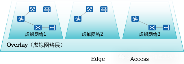
-
Multiple virtual networks can be created based on business needs to achieve business isolation.
-
L2 and L3 communication is achieved through VXLAN.
-
A logical topology based on any physical topology is constructed through virtualization technology.
-
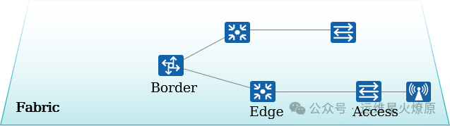
Business networks are created on the Fabric, decoupling from the physical network.
-
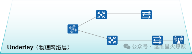
The physical network established by physical devices.
-
Provides interconnectivity for all services within the campus.
-
The foundational carrier network for business data forwarding.
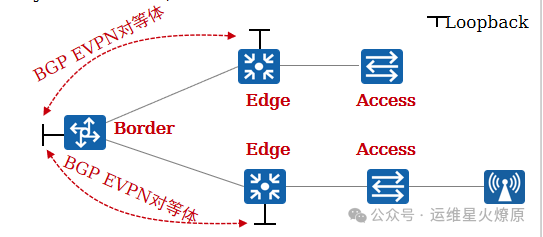
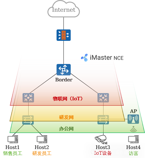
2. Architecture Overview: Network Nodes
-
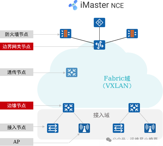
Firewall (Firewall) Node: This node is required when deploying L4~L7 security policies. It can be deployed in-line or at the campus exit.
-
Border Node: Used to achieve interconnectivity between the Fabric and external networks. Generally a core switch.
-
Edge Node: Fabric edge device used to connect user-side devices and the Fabric. Wired user data enters VXLAN encapsulation from the edge node.
-
Transparent Node: A transparent node of the Fabric that does not need to support VXLAN.
-
Access Node: Also known as Extended Node, this is the access node for wired users, which is optional. Users can access the network from here, and the access node does not need to support VXLAN.
-
AP: Wireless access node, users access the wireless network from here and ultimately connect to the Fabric.
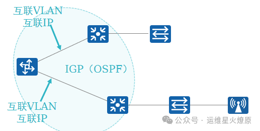
3. Underlay and Fabric
1.Underlay Network
The Underlay network is the “foundation” of the entire campus virtual network, established by physical network devices, providing interconnectivity for all services within the campus.
-
Can be represented as a multi-layer architecture (core, aggregation, and access layers)
-
Can be represented in various topologies (tree, ring, mesh, etc.)
-
Underlay information mainly includes device interconnection VLAN, IP addresses, and IGP
2.Fabric Network
The campus Fabric is a pool of network resources abstracted from physical network devices, pooling Underlay network resources to achieve “one network for multiple uses”.
The information of the Fabric mainly includes:
-
Overlay network resource pool for terminal access (BD-ID, VNI)
-
VLAN ID pool for terminal access
-
Access point pool for terminals (switch ports or SSIDs, i.e., wired or wireless access), etc.
These resource pools can be used to create multiple virtual networks.
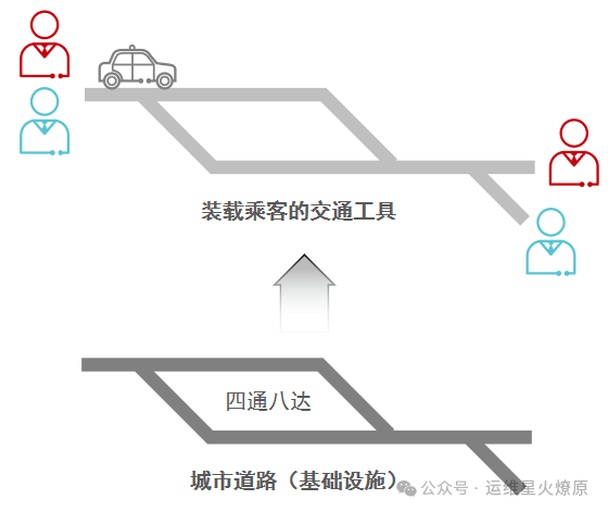
3.Overlay
1.Underlay and Overlay in Real Life
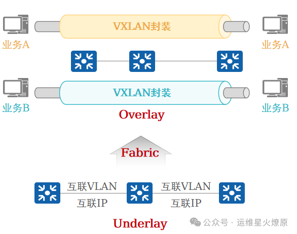
2. Underlay and Overlay in Virtualized Campus Networks
4. What is VN
-
Using VXLAN, several VNs (Virtual Networks, isolated through VXLAN VNI + IP VPN-Instance) can be constructed on the Underlay network.
-
VN is regarded as an Overlay network.
-
Business data for each virtual network is encapsulated in the Fabric through VXLAN to achieve forwarding plane isolation; the control plane uses the BGP EVPN protocol, which is used to establish VXLAN tunnels and exchange Overlay routing information.
Each VN includes the following parameters:
-
Network service resources (DHCP server, third-party RADIUS/Portal server, etc.).
-
External networks (optional).
-
User IP address range, VLAN, and gateway address.
-
Wired access ports and/or wireless access points.
-
Other parameters.
1. Creating VN
VN Settings
-
User gateway location
-
External network
-
Network service resources
-
User subnet and gateway
Wired Access
-
Access site, device, and port
-
Authentication method
-
VLAN information
Wireless Access
-
Access site, device
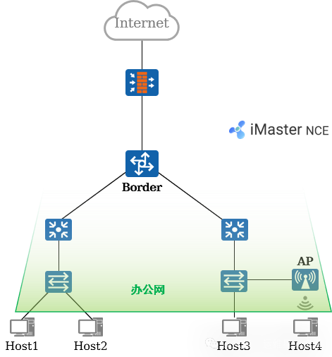
5. Typical Case Analysis: Requirements
Fabric Requirements:
-
Build a Fabric based on the physical network.
-
Adopt a distributed gateway solution.
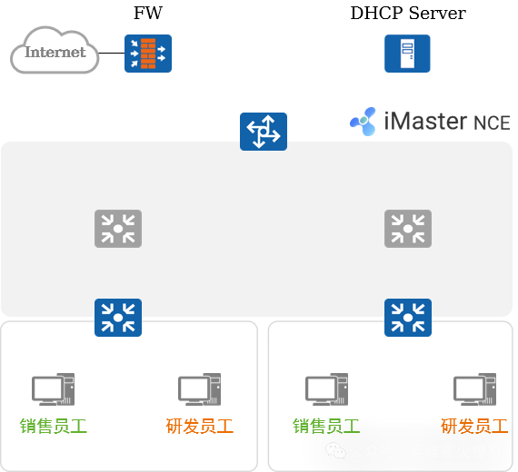
VN Requirements:
-
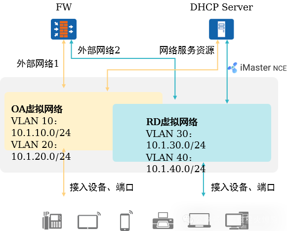
Create 2 VNs, namely Office (OA) and Research (RD).
-
By default, the 2 VNs are completely isolated, and inter-communication within the same subnet and across subnets is possible.
-
Both VNs can access the external network connected to the FW.
-
Terminals within both VNs can obtain IP addresses through the DHCP Server.
1. Typical Case Analysis: Fabric Management (1)
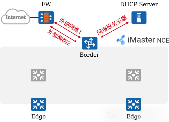
Fabric Creation and Configuration:
-
Users add physical devices (core switches, aggregation switches, and access switches) to the Fabric based on business needs.
-
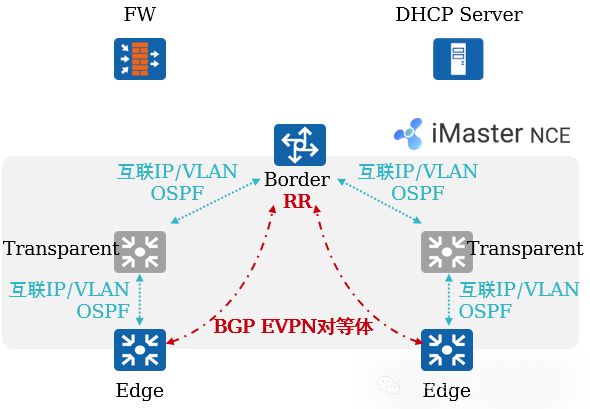
Users specify the role of the switch: Border node and Edge node.
-
iMaster NCE-Campus automatically designates the Border as RR, optimizing the network logical architecture and BGP peer relationship model.
-
Users predefine 2 “external networks” for the 2 VNs to reach external networks.
-
Users define a “network service resource” for subsequent terminals to obtain IP addresses through this resource (including DHCP Server).
2. Typical Case Analysis: Fabric Management (2)
Automated Deployment of Fabric and Underlay Networks:
-
iMaster NCE-Campus automatically orchestrates the network based on the discovered physical network topology combined with the user-defined Fabric network (users can choose OSPF multi-area or single-area).
-
iMaster NCE-Campus automatically issues Underlay network configurations to devices based on the network orchestration results, ensuring IP reachability between devices.
-
iMaster NCE-Campus automatically issues Fabric configurations to devices, establishing BGP EVPN peer relationships between devices, completing the preparation work for the control plane.
3. Typical Case Analysis: VN Management
Creating VN:
-
Users create OA and RD virtual networks on iMaster NCE-Campus, specifying the IP segment/VLAN, gateway address, associated external networks, and network service resources, as well as terminal access points.
-
iMaster NCE-Campus translates user intent into configurations issued to network devices.
4. Typical Case Analysis: Tunnel Establishment
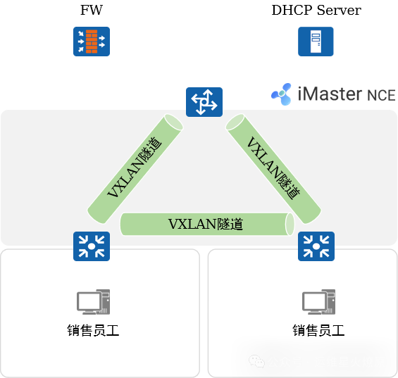
Automatic Establishment of VXLAN Tunnels:
-
BGP EVPN will be used to announce relevant information for establishing VXLAN between peers.
-
Tunnels are established between devices for subsequent data forwarding preparation.
5. Typical Case Analysis: Address Acquisition
Address Acquisition:
-
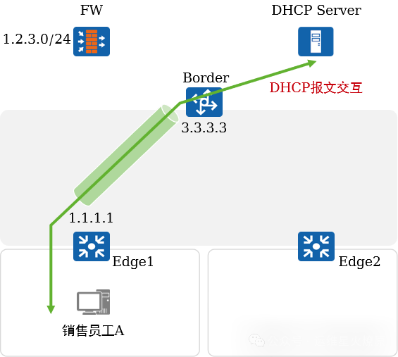
Sales employee A accesses the network, first completing user authentication. After successful authentication, the authentication point Edge1 obtains the authorization result for the user, assigning the user to the corresponding VLAN.
-
A initiates a DHCP request, which reaches the gateway device Edge1. Edge1 relays the DHCP request, and the relay message is forwarded to the Border through the VXLAN tunnel.
-
The Border unencapsulates the VXLAN and forwards the DHCP relay message to the DHCP Server.
-
The DHCP Server assigns an IP address to A.
6. Typical Case Analysis: Same Subnet Intercommunication
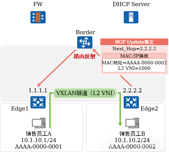
Same subnet intercommunication within the same VN:
-
Sales employees A and B access the campus network through admission authentication.
-
Taking sales employee B as an example, Edge2 announces its MAC address to the Border via BGP, which reflects it back to Edge1.
-
Edge1 learns the MAC address AAAA-0000-0002.
-
When A sends data to B, the traffic reaches Edge1, which performs VXLAN encapsulation and then forwards it to Edge2. Edge2 performs VXLAN decapsulation and delivers the data to the destination.
7. Typical Case Analysis: Cross-Subnet Intercommunication
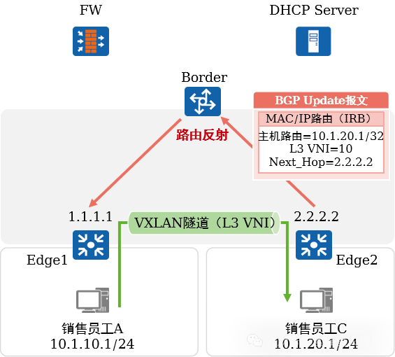
Cross-subnet intercommunication within the same VN:
-
Sales employee C accesses the campus network through admission authentication.
-
Edge2 announces its host route to the Border via BGP, which reflects it back to Edge1.
-
Edge1 learns the route 10.1.20.1/32, with the next hop being 2.2.2.2, and the outgoing interface being the VXLAN tunnel interface.
-
When A sends data to C, the traffic reaches Edge1, which performs VXLAN encapsulation and then forwards it to Edge2. Edge2 performs VXLAN decapsulation and delivers the data to the destination.
8. Typical Case Analysis: Accessing External Networks
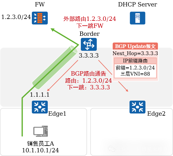
Accessing External Networks:
-
When a user associates an external network (destination subnet 1.2.3.0/24) with the OA virtual network, iMaster NCE-Campus redistributes the external route to BGP and announces it to Edge1 and Edge2.
-
When A sends data to 1.2.3.0/24, the traffic reaches Edge1, which performs VXLAN encapsulation and then sends it to the Border. The Border unencapsulates the VXLAN and forwards the IP packet to the FW.