01
Introduction
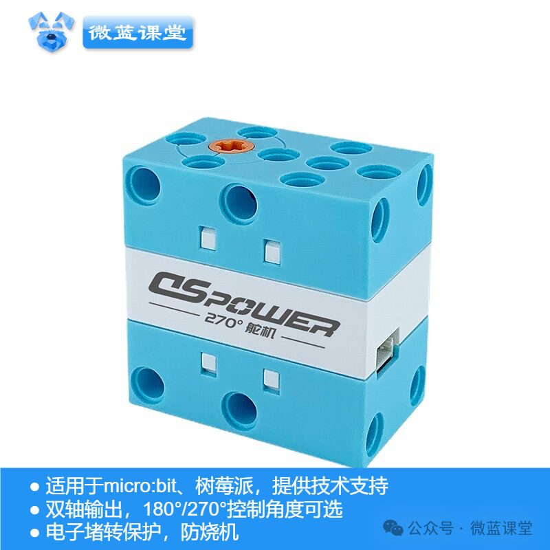
PWM servos are controlled by PWM signals, allowing instantaneous angle changes, with good responsiveness and strong locking capability, but lower precision.
02
Principle
Analog and Digital Signals
First, let’s understand what analog and digital signals are:
- Analog Signal: The micro:bit can output a voltage between 0~3.3V, with parameter values and return values ranging from 0~1023. The pins P0, P1, P2, P3, P4, and P10 on the micro:bit are analog signals, while the others are digital signals.
- Digital Signal: The parameter and return values are limited to computer values 0 and 1, where 1 represents high level (3.3V) and 0 represents low level (0V).
PWM Pulse Width Modulation
The micro:bit pins can only be set to output 3.3V or pull down to 0V. If you want to set an output of 1.65V, you can control it by rapidly toggling the voltage on and off, adjusting the on-time and off-time, which is known as Pulse Width Modulation (PWM).
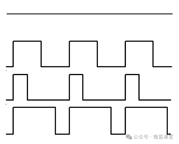
In the image above, you can see four different PWM signal graphs. They all have the same period (and thus frequency), but different duty cycles.
-
The first generated signal is 3.3V, corresponding code: pins.analogWritePin(AnalogPin.P0, 1023)
-
The second signal has a 50% duty cycle, being 3.3V for half the time and 0V for the other half. The output of this signal is 1.65V instead of 3.3V. Corresponding code:
pins.analogWritePin(AnalogPin.P0, 511)
-
The third signal has a 25% duty cycle, which will output 0.825V. Corresponding code: pins.analogWritePin(AnalogPin.P0, 255)
-
The fourth signal has a 75% duty cycle, its energy is three times that of the third signal, equivalent to an output of 2.475V. Corresponding code:
pins.analogWritePin(AnalogPin.P0, 767)
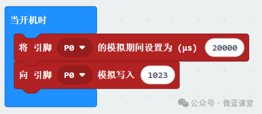
How to Set Frequency?
Set a frequency of 20ms (50Hz):
<span><span>pins.analogSetPeriod(AnalogPin.P0, 20000)</span></span>.
Servo Angle
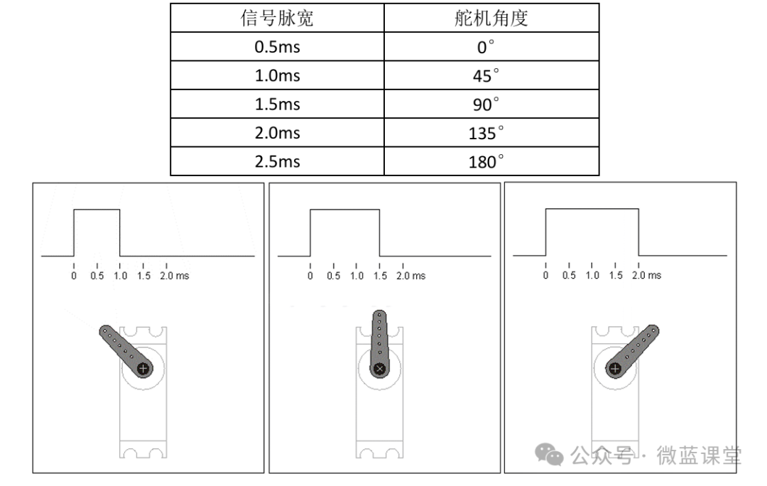
In servo control, the PWM signal parameters are generally: period = 20ms, pulse width (high level width) range = 0.5ms~2.5ms.
The rotation angle of the servo is determined by the pulse width. For example, if a servo has a total rotation angle of 180°, and the PWM pulse width range is 0.5ms~2.5ms, then when the servo receives different pulse width signals, it will turn to the corresponding position (the relationship between signal pulse width and servo angle is linear):
Controlling Servo Rotation Effects
1、Servo Lock: When the signal remains unchanged, the servo will stay in its current position, and the output torque will vary depending on the load.
2、Servo Fast Rotation: When the signal changes, such as from 1ms to 2ms, the servo will rotate from 45° to 135° at maximum speed. This speed will depend on the servo’s performance and load, usually indicated in the specification sheet as the maximum speed under no load.
3、Servo Slow Rotation: When the servo needs to turn slowly, for example, if the servo needs to take three seconds to rotate from 45° to 135°, just calculate the increment of the signal pulse width change, and within the three seconds, increase from 1ms to 2ms at a constant rate. The smaller the increment, the more delicate the rotation effect.
03
Wiring
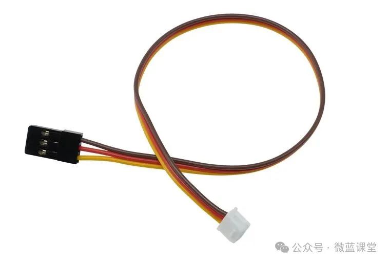
One end of the wire is a 51065 3P connector, and the other end is a JST2.54 3P connector, with three wires:
- G: Power negative, connect to GND, brown wire
- V: Power positive, connect to 3.3V, red wire
- S: Signal wire, connect to P0, yellow wire
04
Program
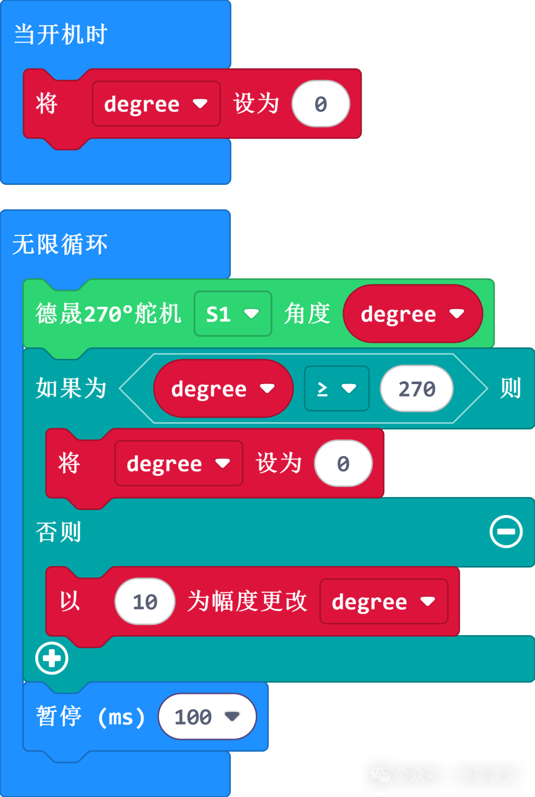
Below is the implementation of the angle for a 270-degree servo:
Pulse Width = Angle / Max Rotatable Range * (Max Pulse Width – Min Pulse Width) + Min Pulse Width
—— Max rotatable angle is 270 degrees, min pulse width is 500μs, max pulse width is 2500μs.
Pulse Width = Angle / Max Rotatable Range * (Max Pulse Width – Min Pulse Width) + Min Pulse Width
Duty Cycle = Pulse Width / Signal Period
—— Signal period is 20000μs.
PWM = Max Supported Bit Length * Duty Cycle
—— Micro:bit supports 10 bits, so it is 1023.
// Rotate to 90 degreeslet degree = 90// Calculate the corresponding pulse width for this angle based on signal period = 20ms, pulse width = 500μs-2500μslet us = Math.floor(degree / 270 * (2500-500)) + 500// Calculate the duty cycle, then calculate pwm value based on 10-bit resolutionlet pwm = Math.floor(us / 20000 * 1023)// Set frequencypins.analogSetPeriod(AnalogPin.P0, 20000)// Set analog signal valuepins.analogWritePin(AnalogPin.P0, pwm05
Demo
I have packaged it into an extension: https://github.com/tim2anna/pxt-microblue, which can be used directly after adding.
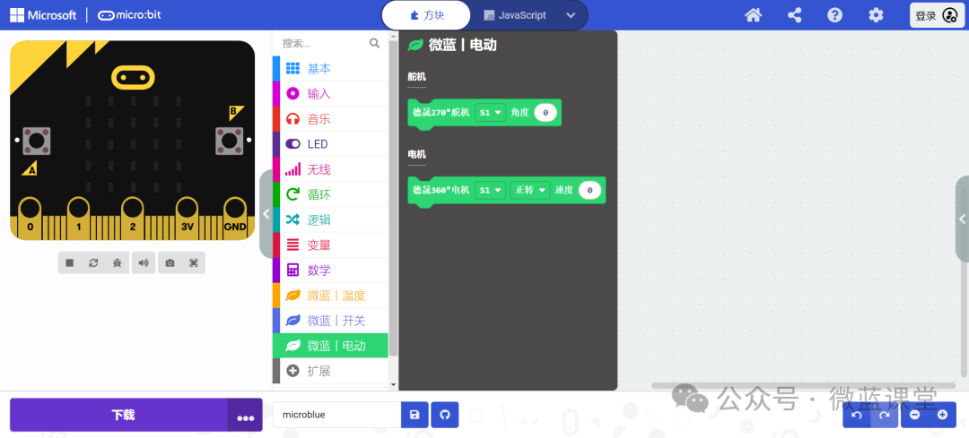
This servo can be purchased from my Taobao store with the same name. Thank you for your support!